1
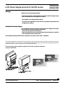
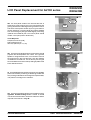
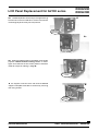
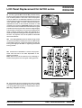
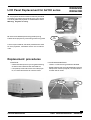
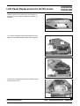
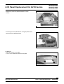
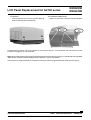
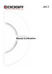
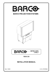
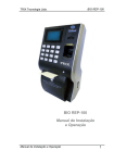
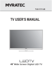
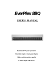
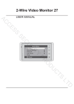
LCD Panel Replacement for G2100 series R808293K R809419K LCD Panel Replacement Flow Chart WARNING LCD PANELS ARE VERY SENSITIVE DEVICES. OBSERVE FULL PRECAUTIONS FOR HANDLING ELECTROSTATIC SENSITIVE DEVICES. For more information about handling electrostatic sensitive devices, see Service manual chapter 'Safety Precautions'. Precautions Handling Precautions: - The LCD module is a glass plate product and is easily damaged by stress. - The LCD module should be handled with care. Do not touch the glass surface and the anti-reflective coating. Hold only by the surrounding metal plate . - Make sure not to apply DC voltage to the product. Module functions are degraded. - The appropriate ANTISTATIC PROTECTION steps should be taken in handling the LCD module. Precautions when Mounting: - Power down the projector and unplug the power cord before starting the replacement. - In case of LCD panel breakage, avoid contact with the liquid. It is harmful if swallowed. Avoid contact with the eyes, skin, or clothing. In case of contact, flush the area with water. Then wash the area with soap and water. - Immediately wipe off any liquid spilled on the display area because its adherence may cause deformation or color spots. - Do not touch the display area and contact terminals with bare hands. Finger prints will cause a smeared image on the screen and could lead to poor connections on the flex foil contacts. Art. No: R5975578 Rev. 01 1 Service Instructions Date: 22/09/98 R808293K - R809419K R808293K R809419K LCD Panel Replacement for G2100 series Storage: Please store the LCD panels as follows: - Place the LCD panels in a dark place with no exposure to direct sunlight or light. Keep temperature within the range of 0°C to 35°C. - Store always in its original package material. - Do not store the image block for more than 50 hours (about 5 days) under direct sunlight (about 10000 lx). Antistatic Protection Steps: If it is impossible to remove a module in a safe area for the replacement of static sensitive parts, the following steps should be taken : - Ensure that the equipment is switched off. - Wear a wrist band which is connected to the ground of the equipment in question while handling the static sensitive parts Use the BARCO tooling kit 2000 series to replace the LCD panel. Order number : R9829530 To be able to replace the LCD-panel of a retro-projector, the projector has to be removed from the projector-cabinet. It will be necessary to remove the front, rightside and leftside panelling, plus the associated strengthening supports of the lower cabinet, by either loosening or removing the fixing nuts. Procedure for removing the projector from the projector-cabinet: (only for RG2100) WHEEL POSITION LOCK 'ON' WHEEL POSITION LOCK 'OFF' þ PRESS ê ý 352-(&7256/,'(5$,/ 21(,7+(56,'(2)352-(&725 6833257&52663/$7( 6833257&5266%$5 5,*+76,'(3$1(/ )5217&21752/3$1(/ )52173$1(/ /()76,'(3$1(/ 2 Service Instructions Date: 22/09/98 R808293K - R809419K R808293K R809419K LCD Panel Replacement for G2100 series a. The front panel needs to be removed and this is achieved by firstly opening the front control panel and gaining access to the two large locking screws on either side of the control panel. Unlock by turning one half turn counter clockwise. The front panel can now be released from its mountings by tilting forwards slightly, then lifting upwards and outwards (the front control panel should remain in the open position at all times). FRONT CONTROL PANEL FRONT PANEL a Tools Required Phillips screw driver (PH0) Flat Top Screw Driver Wrench, Spanner (No- 7,8,10) FRONT PANEL LOCKING SCREWS b. Once the front panel has been removed the internal projector and loud speakers are visible. The right loud speaker is of significance since, if it is chosen to remove the projector from the front direction, then this speaker must also be removed first. This is done by removing all four of its attachment nuts on the top and right pillars of the lower cabinet structure. b PROJECTOR The rightside panel must next be removed. The rightside panel is removed by loosening its attaching screws and then pivoting outwards the front edge of this panel a little, now pull the front edge out to release it. RIGHT SPEAKER RIGHTSIDE PANEL FIXING SCREWS a. Once the right panel has been removed the projector rightside bracket locking screw is visible. A mental note of this screws location should be made as it will be required to be undone in stage . î í a PROJECTOR RIGHTSIDE BRACKET LOCKING SCREW 3 Service Instructions Date: 22/09/98 R808293K - R809419K LCD Panel Replacement for G2100 series R808293K R809419K a. The leftside panel is removed by removing all its fixing screws both on the front and back. Once the screws are removed gently lever evenly out of its position. LEFTSIDE PANEL FRONT FIXING SCREWS a î LEFTSIDE PANEL BACK FIXING SCREWS b. When the leftside panel is completely removed the projector leftside bracket locking screw is visible. Again a mental note of this screws position should be made as it requires undoing in stage . b LEFTSIDE BRACKET LOCKING SCREW The support cross bar at the rear and its attached support cross plate must also be removed by removing their fixing screws. SUPPORT BAR FIXING SCREWS SUPPORT PLATE FIXING SCREWS 4 Service Instructions Date: 22/09/98 R808293K - R809419K R808293K R809419K LCD Panel Replacement for G2100 series The two (rightside a & leftside b) bracket locking screws must be hand un-tightened to release the projector from its locked position. Once this is done the projector must be rotated on its attached brackets from its now operating position to the horizontal slide out position either in the clockwise (b) or counter clockwise directions, dependant on front or rear removal, remember it is still necessary to remove the right audio speaker if choosing to remove from the front side. Exercise caution during this procedure as the projector requires to be nudged slightly (just a couple of centimeters, but ensure the brackets are never in danger of leaving the slide rails) backwards or forwards to facilitate rotating and avoiding obstructions to the lens. The projector can now be pulled out and lifted clear of the cabinet. LOCKING NUT RIGHTSIDE BRACKET LOCKING SCREW a RIGHTSIDE BRACKET LOCKING SCREW a The hand tightable projector bracket locking screws must be undone before the projector can be rotated to the horizontal exit position, it may be necessary to loosen the locking nuts slightly to facilitate un-tightening the bracket locking screws. b 725(029()520)5217 b Access will be available to remove the projector either from the front or the back dependant on the direction of rotation. Note: Extra care must be observed not to damage or scratch the projector lens during the rotating process. A B C Ü 23(5$7,21$/ 326,7,21 OUT 5(029$/ 326,7,21 C B Û A 23(5$7,21$/ 326,7,21 OUT 5(029$/ 326,7,21 725(029()5205($5 The projector can be removed from the rear (rear slide out position) by pulling and gripping firmly until it is fully out. Gently place the projector on a solid stable surface. Warning: Projector is heavy. ê PROJECTOR REMOVAL POSITION FROM REAR 5 Service Instructions Date: 22/09/98 R808293K - R809419K LCD Panel Replacement for G2100 series R808293K R809419K The projector can be removed from the front (front slide out position) by pulling and gripping firmly until it is fully out. Gently place the projector on a solid stable surface. Warning: Projector is heavy. PROJECTOR REMOVAL POSITION FROM FRONT Remove the leftside (when facing the lens) fixing bracket of the projector by unscrewing its two fixing bolts. From this point onwards, the same procedures are used for retro-projectors, retroblocks and for the normal devices. ê PROJECTOR TOP COVER PROJECTOR FIXING BRACKET SCREWS PROJECTOR FIXING BRACKET Replacement procedures For BG2100: - Unlock the back top cover by turning both retaining screws counter clockwise with a screwdriver. - Lift up the top cover and remove it from the projector, the internal structure will now be visible. For RG2100 and RBLG2100: - Loosen or undo the fixing screws as indicated. - Slightly slide the top cover backwards and remove the top cover from the projector, the internal structure will now be visible. PROJECTOR TOP COVER SCREWS ê PROJECTOR TOP COVER ê 6 Service Instructions Date: 22/09/98 R808293K - R809419K R808293K R809419K LCD Panel Replacement for G2100 series - Remove the top cover plate from the projector by turning out the 4 fixation screws (only applies to BG2100). ç è è è - Turn out the indicated screws of the light block cover plate, pivot this plate and lay it down on the projector. - Loosen the 3 indicated screws of the protection cover and remove the cover. 7 Service Instructions Date: 22/09/98 R808293K - R809419K LCD Panel Replacement for G2100 series R808293K R809419K - Unplug the flat cable by opening the cable slot on the connector and by pulling out the flat cable. Connector cable removal/insertion $WWHQWLRQ: connector cables are ORFNHG in the respective connectors 3UHVVWRXQORFN FRQQHFWRU FDEOH Connector 3UHVVWRORFN - Turn out both retaining screws (screwdriver 8 mm). - Slide out the total assembly and lay down carefully on a table. - Slide the new assembly in the 2100 frame so that the centering pins fit into the centering holes. - Secure this position by turning in both retaining screws. - Re-install the flat cable connection and secure by closing the connector slot. 8 Service Instructions Date: 22/09/98 R808293K - R809419K R808293K R809419K LCD Panel Replacement for G2100 series - Replace the protection plate and fasten the three screws. - Pivot the light cover plate back to its original position and secure with the indicated screws. For BG2100: - Place back the top cover plate. - Turn in the 4 indicated screws to fix the plate. ç è è è 9 Service Instructions Date: 22/09/98 R808293K - R809419K LCD Panel Replacement for G2100 series For BG2100: - Lock the back top cover by turning both retaining screws clockwise with a screwdriver. For RG2100 and RBLG2100: - Tighten or put back the fixing screws as indicated. PROJECTOR TOP COVER SCREWS ê R808293K R809419K PROJECTOR TOP COVER ê For RG2100 the projector has to be put back in the projector-cabinet. To do this follow the instructions from the procedure on page 2 to 6 in reverse order. Note: When rotating the projector back to its operational (in the lower cabinet) position you should hear a spring loaded 'click' as the projector brackets engage with the slide rail in the correct position. It will now be correctly positioned for the position locking screws to be tightened at both sides of the projector. 10 Service Instructions Date: 22/09/98 R808293K - R809419K