1
REVISION DATE: 02-02-2009
© 2009, Videolarm, Inc. All Rights Reserved
PRODUCT INSTRUCTIONS
Speci cation
Catalog
Number
Section
INSTRUCTIONS
5288
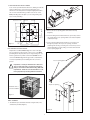
2. To help reinforce the concrete foundation, place (12) 1/2"
diameter x 32" long Reinforcement Bars ("rebar") as shown
3
in Figure 2. Use suitable preparation methods to place
the rebar.
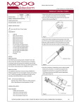
MODEL: Brackets, Mounts, and Poles
P1800
STANDARD INSTALLATION PROCEDURE
6"
24 "
INCLUDES MODELS: P1800
!
6"
Please read these instructions carefully before
proceeding, and heed all cautions.
36"
32"
24"
24 "
NOTE: If you'll be using the optional PV4 anchor
jig, see the attached instructions for
assembly of the jig.
!
Part 1: Site Preparation
32 "
36 "
NOTE: Special attention must be paid to the size of
the wiring conduit and its location within the
concrete foundation and jig (if applicable.)
The Wiring Conduit can be up to 2" in
diameter. Use reducers if necessary.
Also, make sure that the Wiring Conduit is
in the center of the foundation and Anchor
Jig during installation (Figure 1).
!
24"
PV4 Anchor jig (if applicable)
8"
8"
12 "
Figure 1
32"
12 "
36"
Figure 1
Up
to 2" in
1" diameter
maximum
diameter
Wiring conduit
Figure 2
Reinforcement bars (12)
1. Select a suitable site for the P1600 and prepare the pad site
using a hole 36" x 36" x 36" deep. The top of the concrete
foundation should be ush with the ground.
!
CALL BEFORE DIGGING! Be sure that there are no
underground electric or phone cables, gas or water
lines in the area where the pole will be located.
2525 Park Central Blvd. • Decatur, Ga 30035 • (770) 987-7550 • 800-554-1124 U.S. & Canada • www.videolarm.com • Fax 800-826-0366
3. FOR ANCHOR BOLT INSTALLATIONS:
Pour concrete per manufacturer's directions, making sure that the
wiring conduit is in the center of the pad. See Figure 3 for
dimensions of the bolt pattern and suspend appropriate bolts in
the concrete around the wiring conduit. Leave 2" to 3" of the
Bolts protruding above the pad. If you are using leveling nuts,
leave 4" to 6" protruding.
7.778
7.778"
4 x O 1"
4X O 1.000
Based
onONan
11"
BASED
A 11.00"
B.C.B.C.
Figure 5
13.000 7.778
7.778"
13"
2. Remove the access opening plates at the bottom and top
(Figure 6).
4.000
4"
3. Insert the wiring into the transformer base, up into the pole and
out of the bottom access opening. Make sure all slack is pulled
completely through.
O 11"
O 11.000
Figure 3
O 3"
O 3.000
4. Insert connecting wiring into the bottom access opening, run
through the pole up to the top access opening. Insert the
end through the housing connecting hole. Close the top access
opening and make necessary wiring connections at the bottom
access opening (Figure 6).
4"
4.000
13"
13.000
FOR ANCHOR JIG INSTALLATIONS:
Suspend the assembled Anchor Jig in the center of the pad
hole (see Figure 2, previous page). Leave 2" to 3" of the Bolts
protruding above the pad (unless you're using leveling nuts, see
Anchor Jig instructions). Make sure that the Conduit is in the
center of the Anchor Jig. Both the jig and the conduit must be
securely suspended to prevent shifting when the concrete is
poured.
!
Access opening plates
Prepare the concrete per manufacturer's directions.
The concrete must have a compressive strength of
3000 psi, and must be fabricated following ACI318-89
requirements. Allow the concrete foundation to cure
thoroughly before proceeding with the installation.
Top access opening
Schematic view of
concrete foundation
Figure 4
Part 2: Intallation
1. Assemble the pole and transformer base using the bolts, nuts,
and washers provided (Figure 5).
Figure 6
2
5. Place the pole on the pad with the holes on the Transformer Base
aligned with the bolts of the anchor bolts or anchor jig and slowly
lift the pole into the upright position (Figure 7).
CAUTION: Pull all slack in the wiring as
you lift the pole into position
to keep from pinching and
possible damage.
Figure 7
5. Ensure that the pole is vertical on all sides. Use a bubble level or
plumb bob to check.
6. Secure the pole to the pad with fasteners (Figure 8).
Figure 8
3
Wiring Inside the NEMA Box
!
NOTE: This unit MUST be grounded. If you do not have ground on the incoming power, you
MUST run appropriate ground out from the NEMA box
• Run 115 VAC power into the NEMA box through the conduit opening closest to the power transformer. Make
the appropriate connections.
• Run video and control into the NEMA box through the conduit opening closest to the surge protector.
Connect video output to the surge protector. Connect control wiring to the wiring panel in the top of the
NEMA box. Follow the wiring chart on the following page.
Incoming Video
and Control
3.5 amp Transformer Power Surge
115 VAC
Protector
115VAC to 24 VAC
Video Output
Incoming Power
Video Surge
Protector
BNC connector
(use crimped-on
method)
4
Wiring Panel
NEMA Box Wiring Diagram
Video output
1
2
3
4
AC
5
Neutral
6
Ground
115 VAC
24 VAC power
Incoming Power
User Wiring Connections
1
2
3
RED
ORANGE
YELLOW
4
GREEN
TX Control Data
5
6
BLUE
GRAY
Alarm
Alarm
5
RX Control Data
RX Control Data
TX Control Data
pre-connected
Anchor Jig Assembly
4. Before using the Anchor Jig verify that the center to center
dimensions between the bolts are even (Figure 4). If not, adjust
accordingly. Firmly tighten all Hex Nuts.
Anchor Jig Kit Parts List
Single Straps (4)
3/4" Flat Washers (4)
Cross Strap (1)
7
3/4" - 10 Hex Nut (20)
Lock
Washers (4)
/ 32"
3/4" - 10 Bolts (4)
11"
d i a m e te r
1. Thread two (2) nuts onto each of the (4) bolts (Figure 1). The end
with 6" of clearance will be the top of the Anchor Jig, the end with
1 1/2" clearance will be the bottom.
1 1/ 2 "
25
7
25
/ 32"
Figure 4
5. If, due to conditions or other requirements, leveling nuts are
needed, adjustments will have to be made to the Anchor Jig.
Below are diagrams comparing the Anchor Jig with and without
leveling nuts. Leveling nuts and washers are NOT provided with
the pole,
1 1/2"
6"
Figure 1
NOTE: Because of surface conditions it may be necessary to use
leveling nuts. See step 5 below for information.
2. Place the short end of each Bolt into the outside holes of the
Cross Strap. Place Hex Nuts onto each Bolt and finger tighten
(Figure 2).
3. Turn the Anchor Jig over and place Single Straps over the Bolts
(Figure 3). Use the inside hole of each strap. Place Hex Nuts
onto each Bolt and finger tighten.
With Leveling Nuts
Figure 2
Figure 3
NOTE: The Flat Washers, Lock Washers, and remaining Hex Nuts
will be used to fasten the pole to the Anchor Jig.
Without Leveling Nuts
6
IMPORTANT SAFEGUARDS
1. Read Instructions - All the safety and operating instructions should be read
before the unit is operated.
2. Retain Instructions - The safety and operating instructions should be retained
for future reference.
3. Heed Warnings - All warnings on the unit and in the operating instructions
should be adhered to.
4. Follow Instructions - All operating & user instructions should be followed.
5. Electrical Connections - Only a qualified electrician should make electrical
connections.
6. Attachments - Do not use attachments not recommended by the product
manufacturer as they may cause hazards.
7. Cable Runs - All cable runs must be within permissible distance.
8. Mounting - This unit must be properly and securely mounted to a supporting
structure capable of sustaining the weight of the unit. Accordingly:
a. Installation should be made by a qualified installer.
b. Installation should be in compliance with local codes.
c. Care should be exercised to select suitable hardware to install the unit,
taking into account both the composition of the mounting surface and
the weight of the unit. Be sure to periodically examine the unit and the
supporting structure to make sure that the integrity of the installation
is intact. Failure to comply with the foregoing could result in the unit
separating from the support structure and falling, with resultant damages
or injury to anyone or anything struck by the falling unit.
UNPACKING
Unpack carefully. Electronic components can be damaged if improperly handled
or dropped. If an item appears to have been damaged in shipment, replace it
properly in its carton and notify the shipper. Be sure to save:
1. The shipping carton and packaging material. They are the safest material in
which to make future shipments of the equipment.
2. These Installation and Operating Instructions.
SAFETY PRECAUTIONS
!
CAUTION
RISK OF
ELECTRIC SHOCK!
CAUTION: TO REDUCE THE RISK OF
ELECTRICAL SHOCK, DO NOT EXPOSE
COMPONENTS TO WATER OR MOISTURE.
The lightning flash with an arrowhead symbol, within an
equilateral triangle, is intended to alert the user to the
presence of non-insulated "dangerous voltage" within the
product's enclosure that may be of sufficient magnitude
to constitute a risk of electric shock to persons.
!
The exclamation point within an equilateral triangle is
intended to alert the user to presence of important operating
and maintenance (servicing) instructions in the literature
accompanying the appliance.
SERVICE
If the unit ever needs repair service, customer should contact Videolarm
(1-800-554-1124) for return authorization & shipping instructions.
TECHNICAL SUPPORT
Videolarm has set-up a 24 hour technical support line for their customers.
24 HOUR TECHNICAL SUPPORT
1-800-554-1124
LIMITED WARRANTY FOR VIDEOLARM INC. PRODUCTS
VIDEOLARM INC. warrants this Product to be free from defects in material or workmanship, as follows:
PRODUCT CATEGORY
PARTS
LABOR
All Enclosures and Electronics
Five (5) Years
Five (5) Years
Pan/Tilts
Three (3) Years **6 months if used in autoscan
Three (3) Years **6 months if used in autoscan
/ tour operation
Poles/PoleEvators
Three (3) Years / tour operation
Three (3) Years
Warrior/Q-View/I.R. Illuminators
Five (5) Years
Five (5) Years
SView Series
Five (5) Years **6 months if used in autoscan
Five (5) Years
**6 months if used in autoscan
Controllers
Five (5) Years / tour operation
Five (5) Years / tour operation
Power Supplies
Five (5) Years
Five (5) Years
Five (5) Years
Five (5) Years
Accessory Brackets
During the labor warranty period, to repair the Product, Purchaser will either return the defective product, freight prepaid, or deliver it to Videolarm Inc. Decatur GA.
The Product to be repaired is to be returned in either its original carton or a similar package affording an equal degree of protection with a RMA # (Return Materials
Authorization number) displayed on the outer box or packing slip. To obtain a RMA# you must contact our Technical Support Team at 800.554.1124, extension 101.
Videolarm will return the repaired Product freight prepaid to Purchaser. Videolarm is not obligated to provide Purchaser with a substitute unit during the warranty
period or at any time. After the applicable warranty period, Purchaser must pay all labor and/or parts charges.
The limited warranty stated in these product instructions is subject to all of the following terms and conditions:
1. NOTIFICATION OF CLAIMS: WARRANTY SERVICE: If Purchaser believes that the Product is defective in material or workmanship, then written notice
with an explanation of the claim shall be given promptly by Purchaser to Videolarm but all claims for warranty service must be made within the warranty period.
If after investigation Videolarm determines that the reported problem was not covered by the warranty, Purchaser shall pay Videolarm for the cost of investigating
the problem at its then prevailing per incident billable rate. No repair or replacement of any Product or part thereof shall extend the warranty period as to the entire
Product. The specific warranty on the repaired part only shall be in effect for a period of ninety (90) days following the repair or replacement of that part or the
remaining period of the Product parts warranty, whichever is greater.
2. EXCLUSIVE REMEDY: ACCEPTANCE: Purchaser’s exclusive remedy and Videolarm’s sole obligation is to supply (or pay for) all labor necessary to repair
any Product found to be defective within the warranty period and to supply, at no extra charge, new or rebuilt replacements for defective parts.
3. EXCEPTIONS TO LIMITED WARRANTY: Videolarm shall have no liability or obligation to Purchaser with respect to any Product requiring service during
the warranty period which is subjected to any of the following: abuse, improper use: negligence, accident, lightning damage or other acts of God (i.e., hurricanes,
earthquakes), modification, failure of the end-user to follow the directions outlined in the product instructions, failure of the end-user to follow the maintenance
procedures recommended by the International Security Industry Organization, written in product instructions, or recommended in the service manual for the Product.
Furthermore, Videolarm shall have no liability where a schedule is specified for regular replacement or maintenance or cleaning of certain parts (based on usage)
and the end-user has failed to follow such schedule; attempted repair by non-qualified personnel; operation of the Product outside of the published environmental
and electrical parameters, or if such Product’s original identification (trademark, serial number) markings have been defaced, altered, or removed. Videolarm
excludes from warranty coverage Products sold AS IS and/or WITH ALL FAULTS and excludes used Products which have not been sold by Videolarm to the Purchaser.
All software and accompanying documentation furnished with, or as part of the Product is furnished “AS IS” (i.e., without any warranty of any kind), except where
expressly provided otherwise in any documentation or license agreement furnished with the Product.
4. PROOF OF PURCHASE: The Purchaser’s dated bill of sale must be retained as evidence of the date of purchase and to establish warranty eligibility.
DISCLAIMER OF WARRANTY EXCEPT FOR THE FOREGOING WARRANTIES, VIDEOLARM HEREBY DISCLAIMS AND EXCLUDES ALL OTHER WARRANTIES, EXPRESS OR IMPLIED,
INCLUDING, BUT NOT LIMITED TO ANY AND/OR ALL IMPLIED WARRANTIES OF MERCHANTABILITY, FITNESS FOR A PARTICULAR PURPOSE AND/OR ANY WARRANTY WITH REGARD TO ANY CLAIM
OF INFRINGEMENT THAT MAY BE PROVIDED IN SECTION 2-312(3) OF THE UNIFORM COMMERCIAL CODE AND/OR IN ANY OTHER COMPARABLE STATE STATUTE. VIDEOLARM HEREBY DISCLAIMS
ANY REPRESENTATIONS OR WARRANTY THAT THE PRODUCT IS COMPATIBLE WITH ANY COMBINATION OF NON-VIDEOLARM PRODUCTS OR NON-VIDEOLARM RECOMMENDED PRODUCTS
PURCHASER CHOOSES TO CONNECT TO PRODUCT.
LIMITATION OF LIABILITY THE LIABILITY OF VIDEOLARM, IF ANY, AND PURCHASER’S SOLE AND EXCLUSIVE REMEDY FOR DAMAGES FOR ANY CLAIM OF ANY KIND WHATSOEVER,
REGARDLESS OF THE LEGAL THEORY AND WHETHER ARISING IN TORT OR CONTRACT, SHALL NOT BE GREATER THAN THE ACTUAL PURCHASE PRICE OF THE PRODUCT WITH RESPECT TO WHICH
SUCH CLAIM IS MADE. IN NO EVENT SHALL VIDEOLARM BE LIABLE TO PURCHASER FOR ANY SPECIAL, INDIRECT, INCIDENTAL, OR CONSEQUENTIAL DAMAGES OF ANY KIND INCLUDING, BUT NOT
LIMITED TO, COMPENSATION, REIMBURSEMENT OR DAMAGES ON ACCOUNT OF THE LOSS OF PRESENT OR PROSPECTIVE PROFITS OR FOR ANY OTHER REASON WHATSOEVER.
Product Registration/Warranty
Thank you for choosing Videolarm. We value your patronage and are solely committed to
providing you with only the highest quality products available with unmatched customer service
levels that are second-to-none in the security industry.
Should a problem arise, rest assure that Videolarm stands behind its products
by offering some of the most impressive warranty plans available: 3 Years
on all Housings, Poles, Power Supples, and Accessories and 5 Years on
all camera systems (SView, QView, Warriors), and InfraRed Illuminators.
Register Your Products
Option 1: Online
Option 2: Mail-In
Take a few moments and validate your purchase with our Online Product Registration Form
www.videolarm.com/productregistration.jsp
at
or complete and mail-in the bottom portion of this flyer.
Register your recent Videolarm purchases and benefit from the following:
• Simple and Trouble-Free RMA process
• Added into customer database to receive product updates / news
• Eliminate the need to archive original purchase documents:
Receipts, Purchase Orders, etc…
Cut at the dotted Line
Main Contact Info
Place in envelope, affix stamp and mail to: Videolarm ATTN: Warranty
2525 Park Central Ave.
Decatur, GA 30035
First Name:
Last Name:
Professional Title:
Company:
Address 1:
Address 2:
City:
State / Province/Country:
Zip / Postal Code:
Phone Number:
Product Information
Please Circle One:
Name & Location of Company / Store where Purchased:
(City, State, Country)
Videolarm Product ID
Product Description
Serial #
(Available only for Camera Systems, IR Illuminators, Wireless Devices)
PO#
E-mail Address:
Business
Personal