1
Bulletin HY25-1569-M1/US
Owner’s Manual
Power Take-Offs
Effective:
April 2007
Supersedes: HY25-1569-M1/US
January 2007
CAT-D Series
CAT-H Series
WARNING
FAILURE OR IMPROPER SELECTION OR IMPROPER USE OF THE PRODUCTS AND/OR SYSTEMS DESCRIBED
HEREIN OR RELATED ITEMS CAN CAUSE DEATH, PERSONAL INJURY AND PROPERTY DAMAGE.
This document and other information from Parker Hannifin Corporation, its subsidiaries and authorized distributors
provide product and/or system options for further investigation by users having technical expertise. It is important
that you analyze all aspects of your application and review the information concerning the product or system in the
current product catalog. Due to the variety of operating conditions and applications for these products or systems,
the user, through its own analysis and testing, is solely responsible for making the final selection of the products and
systems and assuring that all performance, safety and warning requirements of the application are met.
The products described herein, including without limitation, product features, specifications, designs, availability and
pricing, are subject to change by Parker Hannifin Corporation and its subsidiaries at any time without notice.
Offer of Sale
The items described in this document are hereby offered for sale by Parker Hannifin Corporation, its subsidiaries or
its authorized distributors. This offer and its acceptance are governed by the provisions stated in the "Offer of Sale".
Patent Information
®
The Chelsea Power Take-Off or its components shipped with this owner’s manual may be manufactured under one
or more of the following U.S. patents:
4610175
5228355
4597301
5645363
6151975
6142274
6260682
7159701 B2
Other patents pending.
© Copyright 2007, Parker Hannifin Corporation, All Rights Reserved
II
Parker Hannifin Corporation
Chelsea Products Division
Olive Branch, MS 38654 USA
Owner’s Manual
CAT Rear Mount P.T.O.s
Bulletin HY25-1569-M1/US
Contents
General Information
Safety Information .......................................................................... 1-3
Pump Support Recommendations ............................................... 4
Support Bracket Locations ........................................................... 5
Foreword ........................................................................................ 6
Chelsea P.T.O. Safety Label Instructions ...................................... 7-8
Function of Auxiliary Power Shafts ............................................... 9
Spicer® Universal Joint Engineering Data ................................... 10
Installation Instructions CAT-D Series
Mounting P.T.O. on the Caterpillar Transmission .......................... 11-14
Installation Instructions CAT-H Series
Mounting P.T.O. on the Caterpillar Transmission .......................... 15-17
SK-424 ........................................................................................... 18
Power Take-Off Maintenance .............................................................. 19
Offer of Sale ......................................................................................... 20
III
Parker Hannifin Corporation
Chelsea Products Division
Olive Branch, MS 38654 USA
Bulletin HY25-1569-M1/US
General Information
Owner’s Manual
CAT Rear Mount P.T.O.s
Safety Information
These instructions are for your safety and the safety of the end user. Read
them carefully until you understand them.
General Safety Information
To prevent injury to yourself and/or damage to the equipment:
■ Read carefully all owner’s manuals, service manuals, and/or other
instructions.
■ Always follow proper procedures, and use proper tools and safety equipment.
■ Be sure to receive proper training.
■ Never work alone while under a vehicle or while repairing or maintaining equipment.
■ Always use proper components in applications for which they are approved.
■ Be sure to assemble components properly.
■ Never use wornout or damaged components.
■ Always block any raised or moving device that may injure a person
working on or under a vehicle.
■ Never operate the controls of the Power Take-Off or other driven
equipment from any position that could result in getting caught in the
moving machinery.
Proper Matching of P.T.O.
WARNING: A Power Take-Off must be properly matched to the vehicle
transmission and to the auxiliary equipment being powered. An improperly
matched Power Take-Off could cause severe damage to the vehicle transmission, the auxiliary driveshaft, and/or to the auxiliary equipment being powered.
Damaged components or equipment could malfunction causing serious
personal injury to the vehicle operator or to others nearby.
To avoid personal injury and/or equipment damage:
■ Always refer to Chelsea catalogs, literature, and owner’s manuals.
Follow Chelsea recommendations when selecting, installing, repairing,
or operating a Power Take-Off.
■ Never attempt to use a Power Take-Off not specifically recommended by
Chelsea for the vehicle transmission.
■ Always match the Power Take-Off’s specified output capabilities to the
requirements of the equipment to be powered.
■ Never use a Power Take-Off whose range of speed could exceed the
maximum.
This symbol warns of possible personal injury.
1
Parker Hannifin Corporation
Chelsea Products Division
Olive Branch, MS 38654 USA
Bulletin HY25-1569-M1/US
General Information
Owner’s Manual
CAT Rear Mount P.T.O.s
Safety Information (Continued)
Cold Weather Operation of Powershift P.T.O.
WARNING: During extreme cold weather operation [32°F (0°C) and
lower], a disengaged Powershift Power Take-Off can momentarily transmit
high torque that will cause unexpected output shaft rotation. This is caused
by the high viscosity of the transmission oil when it is extremely cold. As
slippage occurs between the Power Take-Off clutch plates, the oil will rapidly
heat up and the viscous drag will quickly decrease.
The Power Take-Off output shaft rotation could cause unexpected movement
of the driven equipment resulting in serious personal injury, death, or
equipment damage.
To avoid personal injury or equipment damage:
■ Driven equipment must have separate controls.
■ The driven equipment must be left in the disengaged position when not
in operation.
■ Do not operate the driven equipment until the vehicle is allowed to warm up.
Rotating Auxiliary Driveshafts
WARNING:
■ Rotating auxiliary driveshafts are dangerous. You can snag clothes,
skin, hair, hands, etc. This can cause serious injury or death.
■ Do not go under the vehicle when the engine is running.
■ Do not work on or near an exposed shaft when the engine is running.
■ Shut off the engine before working on the Power Take-Off or driven equipment.
■ Exposed rotating driveshafts must be guarded.
Guarding Auxiliary Driveshafts
WARNING: We strongly recommend that a Power Take-Off and a
directly mounted pump be used to eliminate the auxiliary driveshaft
whenever possible. If an auxiliary driveshaft is used and remains exposed
after installation, it is the responsibility of the vehicle designer and P.T.O.
installer to install a guard.
This symbol warns of possible personal injury.
2
Parker Hannifin Corporation
Chelsea Products Division
Olive Branch, MS 38654 USA
Bulletin HY25-1569-M1/US
General Information
Owner’s Manual
CAT Rear Mount P.T.O.s
Safety Information (Continued)
Using Set Screws
WARNING: Auxiliary driveshafts may be installed with either
recessed or protruding set screws. If you choose a square head set screw,
you should be aware that it will protrude above the hub of the yoke and
may be a point where clothes, skin, hair, hands, etc. could be snagged. A
socket head set screw, which may not protrude above the hub of the yoke,
does not permit the same amount of torquing as does a square head set
screw. Also, a square head set screw, if used with a lock wire, will prevent
loosening of the screw caused by vibration. Regardless of the choice made
with respect to a set screw, an exposed rotating auxiliary driveshaft must
be guarded.
Important: Safety Information and Owner’s Manual
Chelsea Power Take-Offs are packaged with safety information decals,
instructions, and an owner’s manual. These items are located in the
envelope with the P.T.O. mounting gaskets. Also, safety information and
installation instructions are packaged with some individual parts and kits.
Be sure to read the owner’s manual before installing or operating
the P.T.O. Always install the safety information decals according to the
instructions provided. Place the owner’s manual in the vehicle glove
compartment.
WARNING: Operating the P.T.O. with the Vehicle in Motion
Some Power Take-Offs may be operated when the vehicle is in motion. To
do so, the P.T.O. must have been properly selected to operate at highway
speeds and correctly matched to the vehicle transmission and the
requirements of the driven equipment.
If in doubt about the P.T.O. specifications and capabilities, avoid operating the P.T.O. when the vehicle is in motion. Improper application and/or
operation can cause serious personal injury or premature failure of the
vehicle, the driven equipment, and/or the P.T.O.
Always remember to disengage the P.T.O. when the driven equipment is
not in operation.
This symbol warns of possible personal injury.
3
Parker Hannifin Corporation
Chelsea Products Division
Olive Branch, MS 38654 USA
Bulletin HY25-1569-M1/US
General Information
Owner’s Manual
CAT Rear Mount P.T.O.s
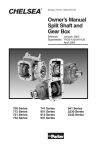
Caterpillar CX31/35 Series Transmissions Maximum Direct Mount
Pump Limits
Maximum Allowable Bending Moment is 80 N·m (60 Lbs-ft) combined.
From the rear P.T.O. mounting face: maximum bending moment includes
PTO, direct mount pump, and unsupported hydraulic lines. Support
brackets designed to reduce the bending moment on the rear P.T.O.
must insure that the 80 N·m (60 Lbs-ft or 720 Lbs-in.) limit cannot be
exceeded. See drawing on page 5 for bracket support locations.
Calculating bending moment:
Lbs-in
= (CGP x PW) + [(LP + CGH) x HPW]
Most measurements will be in inches (in) so we will do the calculation in
inches and convert to Pounds Feet (Lbs-ft).
CAT-H Example
Lbs-in
= (3.74" x 42.5 lbs) + [(8.75" + 4") x 22 Lbs]
=
158.95
+
280.5
= 439.45 Lbs-in divide by 12"
36.6 Lbs-ft Total Bending Moment
CAT-H
Hydraulic Pump
3.74"
LH
CGH
LP
CGP
8.75"
Transmission
Mounting
Face
Key:
LH
=
CGH =
LP
=
CGP =
HPW =
PW
=
CAT-H
CAT-D
Length of Pump
Center of Gravity - Pump
Length of P.T.O.
Center of Gravity - P.T.O.
Hyd. Pump Weight
P.T.O. Weight
= 42.5 lbs
= 8.2 lbs
CAT-D
1.09"
2.60"
CGP
LP
NOTE: If pump center of gravity is not known divide LH by 2
4
Parker Hannifin Corporation
Chelsea Products Division
Olive Branch, MS 38654 USA
Bulletin HY25-1569-M1/US
General Information
Owner’s Manual
CAT Rear Mount P.T.O.s
Support Bracket Locations
If bolts are removed from the CX31 transmission to add mounting
brackets, etc. they must be replaced with longer bolts so that thread
engagement is maintained. The replacement bolts must be of the same
grade and torqued to the required specifications. Thread engagement
length and bolt torques are critical on the Aluminum Case and Cover of
the CX Transmissions. The bolts selected must have a thread Engagement length of twice the bolt diameter. Standard Torques on short bolts
will strip the threads. The bolts must not be too long because the bolts
will bottom out and damage the case.
Bracket Attaching Locations
5
Parker Hannifin Corporation
Chelsea Products Division
Olive Branch, MS 38654 USA
Bulletin HY25-1569-M1/US
General Information
Owner’s Manual
CAT Rear Mount P.T.O.s
Foreword
Since our major objective is to show you how to get additional and more
profitable miles from truck, tractor and trailer components, we want to
provide you with information on the installation of Chelsea Power Take-Offs.
We all realize that an inadequate transmission will overwork any Power
Take-Off in a very short period of time. In addition, a mismatched transmission/ P.T.O. combination can result in unsatisfactory performance of the
equipment right from the start.
Before you order new trucks, be sure you’re getting the right transmission/
P.T.O. combination. It is of vital importance for efficient performance to have
adequate power. To help you select the proper type, size and design of
P.T.O. it is advisable to discuss your specific requirements with Chelsea
P.T.O. specialists. They know their products and have easy access to
manufacturers of equipment, transmissions and Power Take-Offs. They can
inform you about everything you need to know about power, at the right
time, before you specify components.
Exploded View of a Typical Powershift P.T.O.
6
Parker Hannifin Corporation
Chelsea Products Division
Olive Branch, MS 38654 USA
Bulletin HY25-1569-M1/US
Installation Instructions
Owner’s Manual
CAT Rear Mount P.T.O.s
Chelsea P.T.O. Safety Label Instructions
1. The two black and orange on white 5" x 7" pressure sensitive vinyl
labels, part number 379274; must be placed on the vehicle frame rails
(one (1) on each side), in a position that would be HIGHLY visible to
anyone that would go under the truck near the P.T.O. rotating shaft. If the
vehicle is to be painted after these labels are installed, cover them with
two (2) blank masking covers. Remove the masking covers after
painting.
2. Place the one (1) black and orange on white 3.5" x 5" pressure sensitive vinyl label, part number 379275, on the visor nearest the operator
of the vehicle, this must be placed near the P.T.O. visor label.
3. Place the one (1) red and white with black lettering 3.5" x 7.5" sensitive
vinyl label, part number 379915, on the opposite side of the visor from
the above label # 379275.
4. Place the one (1) white and black heavy duty card, part number
379276, in the vehicle glove box. Again in a position highly visible to
the operator, for example: try to place this card on top of whatever may
be in the glove box.
If you require labels, please order part number 328946X at no charge from
your local Chelsea Warehouse or send request direct to:
Parker Hannifin Corporation
Chelsea Products Division
8225 Hacks Cross Road
Olive Branch, MS 38654
Customer Service: (662) 895-1011
7
Parker Hannifin Corporation
Chelsea Products Division
Olive Branch, MS 38654 USA
Bulletin HY25-1569-M1/US
Installation Instructions
Owner’s Manual
CAT Rear Mount P.T.O.s
8
Parker Hannifin Corporation
Chelsea Products Division
Olive Branch, MS 38654 USA
Bulletin HY25-1569-M1/US
Installation Instructions
Owner’s Manual
CAT Rear Mount P.T.O.s
Function of Auxiliary Power Shafts
An auxiliary power shaft transmits torque from the power source to the
driven accessory. The shaft must be capable of transmitting the maximum
torque and R.P.M. required of the accessory, plus any shock loads that
develop.
An auxiliary power shaft operates through constantly relative angles
between the power source and the driven accessory, therefore, the length
of the auxiliary power shaft must be capable of changing while transmitting
torque. This length change, commonly called “slip movement”, is caused
by movement of the power train due to torque reactions and chassis
deflections.
Joint operating angles are very important in an auxiliary power joint
application. In many cases, the longevity of a joint is dependent on the
operating angles. (See chart below)
This information is limited to 1000 through 1310 series applications. For
applications requiring a series larger than 1310, contact your local Chelsea
distributor.
Determining Shaft Type
1) Solid or tubular?
a) In applications requiring more than 1000 R.P.M. or where the
application necessitates a highly balanced auxiliary power shaft, a
tubular shaft should be used.
b) Spicer’s solid shafting auxiliary power joints are designed for 1000
or less R.P.M. intermittent service such as:
Driving small hydraulic pumps
Driving winches
Driving low speed product pumps
2) Joint Series should be determined using the chart on the following
page.
Spicer® Universal Joint Operating Angles
Prop.
Max. Normal
Prop.
Max. Normal
Shaft R.P.M.
Operating Angle Shaft R.P.M.
Operating Angle
3000
5° 50'
1500
11° 30'
2500
7° 00'
1000
11° 30'
2000
8° 40'
500
11° 30'
2
Above based on angular acceleration of 100 RAD/SEC
9
Parker Hannifin Corporation
Chelsea Products Division
Olive Branch, MS 38654 USA
Owner’s Manual
CAT Rear Mount P.T.O.s
Bulletin HY25-1569-M1/US
Installation Instructions
Spicer® Universal Joint Engineering Data
JOINT SERIES
TORQUE RATING
Automotive (Gas or Diesel Engine) lbs. ft.
Continuous
TUBING
Diameter
Wall Thickness
W = WELDED S = SEAMLESS
FLANGE DIAMETER (Swing Diameter)
Rectangular Type
BOLT HOLES - Flange Yoke
Circle
Diameter
Number
Male Pilot Dia.
DISTANCE ACROSS LUGS
Snap Ring
Construction
BEARING DIAMETER
1000
1100
1280
1310
50
54
95
130
1.750
.065
W
1.250 2.500
.095 .083
S
W
3.500
3.500 3.875 3.875
2.750
.312
4
2.250
2.750 3.125 3.125
.312
.375
.375
4
4
4
2.250 2.375 2.375
2.188
2.656 3.469 3.469
.938
.938
3.00
.083
W
1.062 1.062
MAXIMUM OPERATING SPEED * BY TUBE SIZE, SOLID SHAFT SIZE, AND LENGTH
*(For speed below 500 R.P.M. or over 2500 R.P.M., contact your Chelsea Distributor)
Tubing Dia. &
Wall Thickness
Joint & Shaft
(W=Welded
S=Seamless)
1.750" X .065" W
1.250" X .095" S
2.500" X .083" W
3.000" X .083" W
SOLID SHAFT
Diameter
.750"
.812"
.875"
1.000"
1.250"
MAX. INSTALLED LENGTH IN INCHES FOR GIVEN R.P.M.
Centerline to Centerline of Joints For a Two Joint Assembly
or
Centerline of Joint to Centerline of Center Bearing for a Joint & Shaft
R.P.M. - Revolutions per Minute
500
1000
1500
2000
2500
117"
82"
67"
58"
52"
91"
64"
52"
45"
40"
122"
87"
70"
62"
55"
85"
76"
60"
62"
65"
69"
77"
42"
44"
46"
49"
55"
10
35"
36"
37"
40"
45"
30"
31"
32"
35"
39"
27"
28"
29"
31"
35"
Parker Hannifin Corporation
Chelsea Products Division
Olive Branch, MS 38654 USA
Owner’s Manual
CAT-D Series
Bulletin HY25-1569-M1/US
Installation Instructions
Mounting the P.T.O. on the Transmission
When installing a P.T.O., always wear
protective clothing and safety glasses.
WARNING: Oil may be hot. Use
extreme caution to Assure that you do
not accidentally come in contact with
hot oil.
1. Drain transmission oil before
removing the rear aperture plate.
After draining transmission fluid
reinstall plug. (Fig. 1)
Fig. 1
2. Remove the P.T.O. rear aperture
plate with an 18 mm socket.
(Fig. 1)
3. Remove the O-Ring and clean the
aperture surface. (Fig. 2)
NOTE: Do not reuse the O-Ring that
comes with the transmission cover
plate.
Fig. 2
“XV” Output
4. Mounting Constant Drive “XV”
Output.
a. Install O-Ring, furnished with
P.T.O., on transmission mounting
surface (Fig.3). To prevent damage
to O-Ring make sure it is installed in
groove as shown.
b. Install studs as shown in Fig. 4.
Fig. 3
11
Parker Hannifin Corporation
Chelsea Products Division
Olive Branch, MS 38654 USA
Owner’s Manual
CAT-D Series
Bulletin HY25-1569-M1/US
Installation Instructions
Mounting the P.T.O. on the Transmission (continued)
c. DO NOT bottom studs in holes.
Install until shoulder is
approximately one to two threads
from the Transmission mounting
surface. To verify correct
installation measure from end
of stud to transmission mounting
surface. Correct length should
be between 1.31-1.25 in.
[33.2 – 31.8 mm].
Fig. 4
d. Mount P.T.O. as shown in Fig. 5
and install flange nuts.
NOTE: Do not use sealing compounds
because they are generally
incompatible with Automatic
transmission fluid.
Fig. 5
e. Tighten and torque in pattern
shown in Fig. 6. Torque to
55-60 Lbs.-ft. [75-81Nm]
Fig. 6
12
Parker Hannifin Corporation
Chelsea Products Division
Olive Branch, MS 38654 USA
Owner’s Manual
CAT-D Series
Bulletin HY25-1569-M1/US
Installation Instructions
Mounting the P.T.O. on the Transmission (continued)
CAUTION: Caterpillar transmissions have a different weight limit for rear mount
PTO/Pump applications than Chelsea’s recommended limits, see page 4 of this
manual or contact Caterpillar for weight limits on rear mount applications.
Direct Pump Drive Outputs
5.Mounting Constant Drive Pump
Shafts
a. Install O-Ring as shown in
Fig. 7.
Fig. 7
b. Install Studs as shown in Fig. 8
c. DO NOT bottom studs in holes.
Install until shoulder is
approximately one to two threads
from the Transmission mounting
surface. To verify correct
installation measure from end
of stud to transmission mounting
surface. Correct length should
be between 1.31-1.25 in.
[33.2 – 31.8 mm].
Fig. 8
d.Install spring into pump shaft as
shown in Fig 9.
NOTE: Verify that snap ring has been
installed on shaft.
Fig. 9
13
Parker Hannifin Corporation
Chelsea Products Division
Olive Branch, MS 38654 USA
Owner’s Manual
CAT-D Series
Bulletin HY25-1569-M1/US
Installation Instructions
Mounting the P.T.O. on the Transmission (continued)
e. Install P.T.O. shaft into
transmission counter shaft as
shown in Fig 10.
NOTE: Verify that snap ring is installed
on shaft before installing into
transmission.
Fig. 10
f. Mount P.T.O. housing to
transmission as shown in Fig 11.
g. Install flange nuts. Tighten and
torque in a crossing pattern
and Torque to 55-60 Lbs.-ft.
[75-81 Nm].
h. Refill transmission with fluid.
Fig. 11
6. Wet Spline Installation
a. Wet spline installation will be the
same as above (step a thru g
of the pump mount installation
(item 4 page 12)
Plug Installed
b. The P.T.O. housing will not have
an oil seal and there will be a
“plug” (1/8" NPT) in the housing
(Fig. 12).
c. Install O-Ring that is supplied
with kit in flange as shown
(Fig 12).
d. Carefully mount pump so as not
to damage O-Ring and torque as
required.
Fig. 12
Pump
O-Ring
Shaft Seal
Removed
CAUTION: Check Transmission Oil Level before running P.T.O. Assure that the
transmission oil is at the proper level recommended by Caterpillar. Refer to
Caterpillar for correct fluid types.
14
Parker Hannifin Corporation
Chelsea Products Division
Olive Branch, MS 38654 USA
Owner’s Manual
CAT-H Series
Bulletin HY25-1569-M1/US
Installation Instructions
Mounting the P.T.O. on the Transmission
When installing a P.T.O., always wear
protective clothing and safety glasses.
WARNING: Oil may be hot. Use
extreme caution to Assure that you do
not accidentally come in contact with
hot oil.
1. Drain transmission oil before
removing the rear aperture plate.
After draining transmission fluid
reinstall plug.
Fig. 1
2. Remove the P.T.O. rear aperture
plate with an 18 mm socket.
(Fig. 1)
3. Remove the O-Ring and clean the
aperture surface. (Fig. 2)
NOTE: Do not reuse the O-Ring that
comes with the transmission cover
plate.
Fig. 2
4. Install O-Ring, frunished with P.T.O.,
(Fig.3). To prevent damage to
O-Ring make sure it is installed in
groove as shown.
Fig. 3
15
Parker Hannifin Corporation
Chelsea Products Division
Olive Branch, MS 38654 USA
Owner’s Manual
CAT-H Series
Bulletin HY25-1569-M1/US
Installation Instructions
Mounting the P.T.O. on the Transmission (continued)
CAUTION: Caterpillar transmissions have a different weight limit for rear mount
PTO/Pump applications than Chelsea’s recommended limits, see page 4 of this
manual or contact Caterpillar for weight limits on rear mount applications.
5. Install Studs as shown in Fig. 4
DO NOT bottom studs in holes.
Install until shoulder is
approximately one to two threads
from the transmission mounting
surface. To verify correct installation
measure from end of stud to
transmission mounting surface.
Correct length should be between
1.31-1.25 in. [33.2 – 31.8 mm].
NOTE: Prior to mounting the P.T.O.
install pressure switch into P.T.O.
housing as shown in Fig. 5. Torque to
10-12 Lbs. ft. [13-16 N.m].
Fig. 4
6. Mount P.T.O. to transmission as
shown using the flange nuts
provided with Power Take-Off.
NOTE: Position of P.T.O. solenoid
between 12 o’clock and 2 o’clock
position when viewed from rear. (Fig.5)
Tighten and Torque flange nuts in a
crossing pattern to 50-60 Lbs.-ft.
Fig. 5
[75-81 N.m]
7. Install the 90° elbow in the
transmission pressure port as
shown. Connect hose to the
transmission port as shown.
Connect other end of hose to the
P.T.O. 90° elbow located near the
P.T.O. solenoid. (Fig 6)
Fig. 6
16
Parker Hannifin Corporation
Chelsea Products Division
Olive Branch, MS 38654 USA
Owner’s Manual
CAT-H Series
Bulletin HY25-1569-M1/US
Installation Instructions
Mounting the P.T.O. on the Transmission (continued)
8. Keep the bend radius of the hose
as large as possible to avoid
collapsing the hose and restriction
of flow. Minimum bend radius is
measured on the inside bend of the
hose. To determine minimum bend,
divide the total distance between
ends (B length) by 2. For example,
B =6", minimum bend radius = 3"
Fig.7
9. Route hose and secure to stay out
of the path (swing diameter) of the
transmission output yoke. (Fig 7)
NOTE: It is not recommended to route
the hose under the P.T.O. due to the
possibility of the hose being exposed
to road hazards.
Fig. 8
10. See SK-424, pg. 18 for complete
wiring & plumbing installation
information.
11. Refill transmission with fluid.
CAUTION: Check Transmission Oil Level before running P.T.O. Assure that the
transmission oil is at the proper level recommended by Caterpillar. Refer to
Caterpillar for correct fluid types.
17
Parker Hannifin Corporation
Chelsea Products Division
Olive Branch, MS 38654 USA
18
379486 Fitting (Elbow 90°)
Installed in Rear of Transmission
Positive Terminal of
Ignition or Battery
379257 Splice
Connector
379336
Bracket
379502 Pressure Switch Torque to
120-144 In-lbs
379900 Fuse
Holder Ass’y
w/ 10 AMP Fuse
378881
Switch
379306 Spade
Connector
Red Wire
379252 Butt
Connector
Run Wires Through
Grommet in Firewall
378978 12V
Indicator Light
379005 24V
Indicator Light
Installation Instructions
Secure Hose to Keep Away
From Driveshaft Yoke
Drill 1" Dia.
Hole in Firewall
379928 Valve Connector
and Wire Ass’y
Blue Wire
379265
Slice Grommet Grommet
insert in Hole
in Firewall
Black Wire
329075-1X Hose Ass’y (Normal Mounting)
if P.T.O. is Rotated Further Clockwise a
Longer Hose may be needed
Electrical Ground
of Cab or Frame
Accepts #10 Screw
Bulletin HY25-1569-M1/US
Owner’s Manual
Caterpillar
12v Electrical & Hydraulic Installation CAT-H
(SK-424 Rev A)
Parker Hannifin Corporation
Chelsea Products Division
Olive Branch, MS 38654 USA
Owner’s Manual
10-Bolt Powershift P.T.O.s
Bulletin HY25-1569-M1/US
Power Take-Off Maintenance
Power Take-Off Maintenance
Due to the normal and sometime severe torsional vibrations that Power
Take-Off units experience, operators should follow a set maintenance
schedule for inspections. Failure to service loose bolts or Power Take-Off
leaks could result in potential auxiliary Power Take-Off or transmission
damage.
Periodic P.T.O. MAINTENANCE is required by the owner/operator to ensure
proper, safe and trouble free operation.
Daily:
Check all air, hydraulic and working mechanisms before operating
P.T.O. Perform maintenance as required.
Monthly: Inspect for possible leaks and tighten all air, hydraulic and
mounting hardware, if necessary. Torque all bolts, nuts, etc.
to Chelsea specifications. Insure that splines are properly
lubricated, if applicable. Perform maintenance as required.
With regards to the direct mounted pump splines, the P.T.O. requires the
application of a specially formulated anti-fretting, high pressure, high
temperature grease. The addition of the grease has been proven to reduce
the effects of the torsional vibrations, which result in fretting corrosion on
the P.T.O. internal splines as well as the pump external splines. Fretting
corrosion appears as a “rusting and wearing” of the pump shaft splines.
Severe duty applications, which require long P.T.O. running times and high
torque may require more frequent regreasing. Applications such as Utility
Trucks that run continuously and are lightly loaded also require frequent
regreasing due to the sheer hours of running time. It is important to note
that service intervals will vary for each and every application and is the
responsibility of the end user of the product. Chelsea also recommends
that you consult your pump owners manuals and technical services for
their maintenance guidelines. Fretting corrosion is caused by many factors
and without proper maintenance; the anti-fretting grease can only reduce its
effects on components.
Chelsea offers the grease to our customers in two packages. The first is a
5/8 fluid ounce tube (379688), which is included with every applicable
P.T.O., and the second is a 14-ounce grease cartridge (379831). Chelsea
also offers greaseable shafts for most all output designators.
Warranty: Failure to comply entirely with the provisions set forth in
the appropriate Owner’s Manual will result in voiding of ALL
Warranty consideration.
19
Parker Hannifin Corporation
Chelsea Products Division
Olive Branch, MS 38654 USA
Offer of Sale
The items described in this document and other documents or descriptions provided by Parker Hannifin Corporation, its subsidiaries and
its authorized distributors are hereby offered for sale at prices to be established by Parker Hannifin Corporation, its subsidiaries and its
authorized distributors. This offer and its acceptance by any customer ("Buyer") shall be governed by all of the following Terms and
Conditions. Buyer’s order for any such items, when communicated to Parker Hannifin Corporation, its subsidiary or an authorized
distributor ("Seller") verbally or in writing, shall constitute acceptance of this offer.
1. Terms and Conditions of Sale: All descriptions, quotations,
proposals, offers, acknowledgments, acceptances and sales of
Seller’s products are subject to and shall be governed exclusively
by the terms and conditions stated herein. Buyer’s acceptance of
any offer to sell is limited to these terms and conditions. Any terms
or conditions in addition to, or inconsistent with those stated herein,
proposed by Buyer in any acceptance of an offer by Seller, are
hereby objected to. No such additional, different or inconsistent
terms and conditions shall become part of the contract between
Buyer and Seller unless expressly accepted in writing by Seller.
Seller’s acceptance of any offer to purchase by Buyer is expressly
conditional upon Buyer’s assent to all the terms and conditions
stated herein, including any terms in addition to, or inconsistent
with those contained in Buyer’s offer, Acceptance of Seller’s
products shall in all events constitute such assent.
2. Payment: Payment shall be made by Buyer net 30 days from the
date of delivery of the items purchased hereunder. Amounts not
timely paid shall bear interest at the maximum rate permitted by law
for each month or portion thereof that the Buyer is late in making
payment. Any claims by Buyer for omissions or shortages in a
shipment shall be waived unless Seller receives notice thereof
within 30 days after Buyer’s receipt of the shipment.
3. Delivery: Unless otherwise provided on the face hereof, delivery shall be made F.O.B. Seller’s plant. Regardless of the method
of delivery, however, risk of loss shall pass to Buyer upon Seller’s
delivery to a carrier. Any delivery dates shown are approximate
only and Seller shall have no liability for any delays in delivery.
4. Warranty: Seller warrants that the items sold hereunder shall be
free from defects in material or workmanship for a period of:
(A) All Power Take-Off units one (1) year from date of installation.
(B) Except 267, 277, 278, 242, 244, 246, 250, 251 and 859 series
two (2) years from date of installation.
THIS WARRANTY COMPRISES THE SOLE AND ENTIRE WARRANTY PERTAINING TO ITEMS PROVIDED HEREUNDER.
SELLER MAKES NO OTHER WARRANTY, GUARANTEE, OR
REPRESENTATION OF ANY KIND WHATSOEVER. ALL OTHER
WARRANTIES, INCLUDING BUT NOT LIMITED TO, MERCHANTABILITY AND FITNESS FOR PURPOSE, WHETHER
EXPRESS, IMPLIED, OR ARISING BY OPERATION OF LAW,
TRADE USAGE, OR COURSE OF DEALING ARE HEREBY
DISCLAIMED. NOTWITHSTANDING THE FOREGOING, THERE
ARE NO WARRANTIES WHATSOEVER ON ITEMS BUILT OR
ACQUIRED WHOLLY OR PARTIALLY, TO BUYER’S DESIGNS
OR SPECIFICATIONS.
5. Limitation Of Remedy: SELLER’S LIABILITY ARISING FROM
OR IN ANY WAY CONNECTED WITH THE ITEMS SOLD OR
THIS CONTRACT SHALL BE LIMITED EXCLUSIVELY TO REPAIR OR REPLACEMENT OF THE ITEMS SOLD OR REFUND
OF THE PURCHASE PRICE PAID BY BUYER, AT SELLER’S
SOLE OPTION. IN NO EVENT SHALL SELLER BE LIABLE FOR
ANY INCIDENTAL, CONSEQUENTIAL OR SPECIAL DAMAGES
OF ANY KIND OR NATURE WHATSOEVER, INCLUDING BUT
NOT LIMITED TO LOST PROFITS ARISING FROM OR IN ANY
WAY CONNECTED WITH THIS AGREEMENT OR ITEMS SOLD
HEREUNDER, WHETHER ALLEGED TO ARISE FROM BREACH
OF CONTRACT, EXPRESS OR IMPLIED WARRANTY, OR IN
TORT, INCLUDING WITHOUT LIMITATION, NEGLIGENCE,
FAILURE TO WARN OR STRICT LIABILITY.
6. Changes, Reschedules and Cancellations: Buyer may request to modify the designs or specifications for the items sold
hereunder as well as the quantities and delivery dates thereof, or
may request to cancel all or part of this order, however, no such
requested modification or cancellation shall become part of the
contract between Buyer and Seller unless accepted by Seller in a
written amendment to this Agreement. Acceptance of any such
requested modification or cancellation shall be at Seller’s discretion, and shall be upon such terms and conditions as Seller may
require.
7. Special Tooling: A tooling charge may be imposed for any
special tooling, including without limitation, dies, fixtures, molds
and patterns, acquired to manufacture items sold pursuant to this
contract. Such special tooling shall be and remain Seller’s property
notwithstanding payment of any charges by Buyer. In no event will
Buyer acquire any interest in apparatus belonging to Seller which
is utilized in the manufacture of the items sold hereunder, even if
such apparatus has been specially converted or adapted for such
manufacture and notwithstanding any charges paid by Buyer.
Unless otherwise agreed, Seller shall have the right to alter, discard
or otherwise dispose of any special tooling or other property in its
sole discretion at any time.
8. Buyer’s Property: Any designs, tools, patterns, materials,
drawings, confidential information or equipment furnished by Buyer
or any other items which become Buyer’s property, may be considered obsolete and may be destroyed by Seller after two (2)
consecutive years have elapsed without Buyer placing an order for
the items which are manufactured using such property, Seller shall
not be responsible for any loss or damage to such property while
it is in Seller’s possession or control.
9. Taxes: Unless otherwise indicated on the face hereof, all prices
and charges are exclusive of excise, sales, use, property, occupational or like taxes which may be imposed by any taxing authority
upon the manufacture, sale or delivery of the items sold hereunder.
If any such taxes must be paid by Seller or if Seller is liable for the
collection of such tax, the amount thereof shall be in addition to the
amounts for the items sold. Buyer agrees to pay all such taxes or
to reimburse Seller therefore upon receipt of its invoice. If Buyer
claims exemption from any sales, use or other tax imposed by any
taxing authority, Buyer shall save Seller harmless from and against
any such tax, together with any interest or penalties thereon which
may be assessed if the items are held to be taxable.
10. Indemnity For Infringement of Intellectual Property Rights:
Seller shall have no liability for infringement of any patents, trademarks, copyrights, trade dress, trade secrets or similar rights
except as provided in this Part 10. Seller will defend and indemnify
Buyer against allegations of infringement of U.S. Patents, U.S.
Trademarks, copyrights, trade dress and trade secrets (hereinafter
‘Intellectual Property Rights’). Seller will defend at its expense and
will pay the cost of any settlement or damages awarded in an action
brought against Buyer based on an allegation that an item sold
pursuant to this contract infringes the Intellectual Property Rights
of a third party. Seller’s obligation to defend and indemnify Buyer
is contingent on Buyer notifying Seller within ten (10) days after
Buyer becomes aware of such allegations of infringement, and
Seller having sole control over the defense of any allegations or
actions including all negotiations for settlement or compromise. If
an item sold hereunder is subject to a claim that it infringes the
Intellectual Property Rights of a third party, Seller may, at its sole
expense and option, procure for Buyer the right to continue using
said item, replace or modify said item so as to make it noninfringing,
or offer to accept return of said item and return the purchase price
less a reasonable allowance for depreciation. Notwithstanding the
foregoing, Seller shall have no liability for claims of infringement
based on information provided by Buyer, or directed to items
delivered hereunder for which the designs are specified in whole or
part by Buyer, or infringements resulting from the modification,
combination or use in a system of any item sold hereunder. The
foregoing provisions of this Part 10 shall constitute Seller’s sole and
exclusive liability and Buyer’s sole and exclusive remedy for
infringement of Intellectual Property Rights.
If a claim is based on information provided by Buyer or if the design
for an item delivered hereunder is specified in whole or in part by
Buyer, Buyer shall defend and indemnify Seller for all costs,
expenses or judgments resulting from any claim that such item
infringes any patent, trademark, copyright, trade dress, trade
secret or any similar right.
11. Force Majeure: Seller does not assume the risk of and shall not
be liable for delay or failure to perform any of Seller’s obligations by
reason of circumstances beyond the reasonable control of Seller
(hereinafter ‘Events of Force Majeure’). Events of Force Majeure
shall include without limitation, accidents, acts of God, strikes or
labor disputes, acts, laws, rules or regulations of any government
or government agency, fires, floods, delays or failures in delivery of
carriers or suppliers, shortages of materials and any other cause
beyond Seller’s control.
12. Entire Agreement/Governing Law: The terms and conditions
set forth herein, together with any amendments, modifications and
any different terms or conditions expressly accepted by Seller in
writing, shall constitute the entire Agreement concerning the items
sold, and there are no oral or other representations or agreements
which pertain there/to. This Agreement shall be governed in all
respects by the law of the State of Ohio. No actions arising out of
the sale of the items sold hereunder or this Agreement may be
brought by either party more than two (2) years after the cause of
action accrues.
1/06-P
20
Parker Hannifin Corporation
Chelsea Products Division
Olive Branch, MS 38654 USA
Parker Hannifin Corporation
Chelsea Products Division
8225 Hacks Cross Road
Olive Branch, Mississippi 38654 USA
Tel: (662) 895-1011
Fax: (662) 895-1019
www.parker.com/chelsea
FP 4/07 1C