1
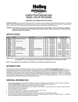
STREET AVENGER CARBURETOR P/N 0-80570, 0-80670, 0-80770, 0-80870, 0-81570, 0-81670, & 0-81770 INSTALLATION, TUNING, AND ADJUSTMENT MANUAL 199R-10219-3 NOTE: These instructions must be read and fully understood before beginning installation. If this manual is not fully understood, installation should not be attempted. Failure to follow these instructions, including the pictures may result in subsequent system failure. TABLE OF CONTENTS: INTRODUCTION: .........................................................................................................................3 REMOVAL: ..................................................................................................................................3 INSTALLATION NOTES:.............................................................................................................3 CHRYSLER APPLICATIONS ......................................................................................................................................3 FORD APPLICATIONS ................................................................................................................................................4 GM APPLICATIONS ....................................................................................................................................................5 INSTALLATION: ..........................................................................................................................5 CHOKE ADJUSTMENT: ..............................................................................................................8 IDLE MIXTURE NEEDLES: .........................................................................................................9 FLOAT LEVEL ADJUSTMENT:.................................................................................................10 VACUUM OPERATED SECONDARY THROTTLES:................................................................11 VACUUM OPERATED SECONDARY TUNING: .......................................................................12 JETTING (MAIN JETS):.............................................................................................................13 CARBURETOR SPECIFICATIONS: ..........................................................................................13 HOLLEY STREET AVENGER LIMITED LIFETIME WARRANTY ........................................14 2 INTRODUCTION: CONGRATULATIONS on your purchase of the Street Avenger Carburetor! We feel that you have purchased the finest street performance carburetor manufactured today. Should you need information or parts assistance, please contact our Avenger Technical Service Department at 1-866-GOHOLLEY (1-866-464-6553). Please have the part number and sales receipt ready when calling. IMPORTANT: The STREET AVENGER carburetor has been factory wet-flowed and calibrated. The “out of the box” settings should be very close for all adjustments. To preserve warranty, these instructions must be read and followed thoroughly before and during installation. NOTE: The Street Avenger Carburetor kit has not yet been submitted for emissions testing and therefore, has not received an Executive Order Exemption from the California Resources Board. This means that your vehicle will NOT be “Smog Legal” in all 50 states with this kit installed. WARNING: If you are using this carburetor with a GM overdrive transmission TH700R4 or a TH200R4, you must use a transmission kickdown cable bracket (Holley P/N 20-95) and stud (Holley P/N 20-2, 20-38, or 20-40). Otherwise, SEVERE transmission damage WILL result. This carburetor is not designed to work with ANY other automatic overdrive transmissions. These carburetors have been designed and calibrated as a universal replacement carburetor for passenger cars and light truck applications equipped with V-6 and V-8 engines. It is designed for use on “square” flange intake manifolds. Carburetor adapters are not recommended to adapt to “spread” bore intake manifolds, since adapters may have an adverse affect on cylinder-to-cylinder distribution and ultimately, total engine performance. However, some manifolds may be universal (such as Weiand 8004). Please check with Holley’s Avenger Technical Service Department if you have any questions. REMOVAL: 1. Remove the air cleaner, exercising care to carefully detach any vacuum lines to the air cleaner and marking them so they can be reassembled to the air cleaner in the same manner. 2. Remove the existing carburetor by the following procedure: A. Carefully disconnect the fuel line. WARNING: Carefully protect the open end of the fuel lines, so that no foreign particles can enter. Wrap the end of the fuel line with a clean lint-free cloth. B. C. D. E. F. 3. Disconnect and mark all the vacuum lines to the carburetor. Disconnect the PCV hose. Disconnect the choke rod or heat tubes (if equipped). Disconnect and remove the throttle linkage and automatic kickdown linkage. SAVE ALL RETAINING CLIPS. Unbolt and remove the carburetor from the manifold. If the intake manifold is being changed at this time, install the new manifold according to the manifold’s manufacturer’s directions. Since we are not familiar with all manifold instructions, Holley cannot accept responsibility for their validity. We recommend that you only use Holley Street Avenger manifolds, which you can find in the Street Avenger catalog included with your kit. INSTALLATION NOTES: CHRYSLER APPLICATIONS WARNING: This carburetor is not designed for use with any Chrysler automatic overdrive transmission. SEVERE transmission damage may result from improper application use. 1. If you are replacing an existing Holley carburetor, you may need to purchase and install a throttle lever extension (Holley P/N 20-7) on the carburetor. Remove the throttle stud and nut from the original carburetor. You can purchase a new stud from your Holley dealer (Holley P/N 20-36). Install the stud in the throttle extension lever (Figure 1). 3 Figure 1—Chrysler applications FORD APPLICATIONS NOTE: Unless replacing an existing Holley Carburetor, you will need to purchase Holley P/N 20-91, spring and perch kit, for Ford automatic transmissions. 1. Install the new throttle ball, lockwasher, and retaining nut to the carburetor throttle lever in the same position as the existing carburetor. 2. Insert the transmission kickdown screw with the black retaining clip on the transmission kickdown lever (Figure 2). This assembly must be installed according to the detailed drawing (Figure 3). Figure 2—Ford applications 4 3. Remove the lock out screw from the kickdown lever (Figure 4). 4. Install the transmission kickdown spring between the transmission kickdown lever and spring perch on the solenoid/dashpot bracket (Figure 2). Figure 3—Ford applications Figure 4—Ford applications GM APPLICATIONS WARNING: If you are using this carburetor with a GM overdrive transmission TH700R4 or a TH200R4, you must use a transmission kickdown cable bracket (Holley P/N 20-95) and stud (Holley P/N 20-2, 20-38, or 20-40). Otherwise, SEVERE transmission damage WILL result. This carburetor is not designed to work with ANY other automatic overdrive transmission. 1. Remove the throttle cable ball and automatic transmission kickdown stud (if any) from the original carburetor, and mount these in similar locations on the Holley throttle lever. If the original throttle cable is too large, a new throttle ball or stud is needed (Holley P/N 20-2, 20-38, or 20-40). INSTALLATION: 1. Install the carburetor-mounting studs in the proper location on the intake manifold carburetor flange. 2. Place the new carburetor flange gasket, provided with the carburetor, in the proper position on the intake manifold. 3. Place the carburetor on top of the flange gasket on the manifold. Install the hold down nuts and snug down progressively in a “crisscross” pattern (60-80 in./lbs.), as shown in Figure 5. Figure 5 WARNING: Overtightening may result in warped or cracked carburetor throttle body. 4. Before connecting the linkage, operate the throttle lever to ensure the correct travel (no sticking or binding), by opening to wide-open throttle and back to closed throttle several times. Correct any sticking or binding conditions before proceeding. 5 5. Reconnect the throttle and transmission kickdown linkage and throttle return spring (Holley P/N 20-89). Operate the carburetor throttle lever by hand to ensure the correct travel (no sticking or binding) by opening to wide-open throttle and back to closed throttle several times. Correct any sticking or binding conditions before proceeding. NOTE: With the engine turned off, have an assistant slowly press the accelerator pedal to the floor, while you watch the throttle for any sticking or binding. Correct any sticking or binding conditions before proceeding. Also ensure that you are reaching full throttle. Many performance problems are traced to partial throttle openings from improperly adjusted linkage. Figure 6 6. Reconnect the appropriate vacuum hoses to the carburetor, noting the correct fitting from Figure 6 and 8. A. B. The full manifold vacuum source in the front of the throttle body provides vacuum for proper operation of the air cleaner, the pump diverter valve (if equipped), AC/Cruise, and/or the temperature sensing valve. If vacuum for more than one component is needed, use small plastic vacuum “T”s (available at most automotive stores). The timed spark fitting in the choke side of the primary metering block provides vacuum for the operation of the distributor vacuum advance. Connect the hose to the distributor, spark delay valve, and/or temperature sensing valve as originally connected. Again use “T”s as necessary. If any questions arise about the hose connections, consult the proper service manual. 7. Connect the PCV hose to the PCV fitting in the carburetor. 8. Connect the power brake hose to the fitting as shown in Figures 6 or 8. 9. Assemble the fuel line assembly as shown in Figure 7. 10. In some cases, the existing fuel line will have to be cut and connected to the fuel line assembly from step 9 with a length of rubber fuel hose and clamp. 6 Figure 7 Figure 8 WARNING: During the fuel line installation, DO NOT allow any foreign particles to enter the fuel lines, which could then cause flooding and may result in a fire. WARNING: Keep the fuel line away from the EGR valve (if equipped) on the intake manifold. If installation requires cutting the metal fuel line, cut the fuel line with a good tube cutter. This will minimize the chance of producing metal chip particles. If a hacksaw must be used then metal chips must be removed. WARNING: In all cases where the fuel line has been cut, it is essential that it be clean to ensure that no metal particles enter the fuel bowl after the new carburetor installation. Remove the fuel line at the pump and blow the line clean with compressed air. DO NOT use the procedure where the coil wire is disconnected, the engine cranked for a few revolutions, and the fuel collected in a container. This procedure is unsafe because sparking can occur either at the coil or at the distributor end of the coil wire and ignite any fuel spilled in the engine compartment. CAUTION: This carburetor contains in line Morain fuel filters. However, the use of a quality in line fuel filter, such as Holley P/N 162-523 is mandatory as a safeguard against possible flooding, which could result from unfiltered particles becoming lodged between the fuel inlet needle and its seat. This can result in fire if a spark is present or backfire occurs in the engine compartment. Air cleaner filter elements should be blown clean with compressed air at 6,000 miles and replaced at 12,000 miles to ensure maximum protection. Now would be the perfect time to upgrade to a Holley Powershot air cleaner filter. 11. For electric choke hookup, attach the bayonet end of the long electrical lead supplied to the positive terminal on the choke cap. The other end must be connected to an ignition activated 12-volt source. The distributor side of the ignition coil is NOT a 12-volt source. It is a 7-9-volt source after cranking. WARNING: Connecting the choke cap to the ignition or ignition coil could result in unacceptable choke operation, poor fuel economy, and possible engine misfiring, since the voltage delivered to the spark plugs will be severely reduced by the drain imposed by the choke cap. Suitable ignition activated 12-volt sources are most electrical relays, as well as the leads to accessories, such as windshield wipers. DO NOT connect this wire to the original equipment (O.E.) electric choke source. This may not be a 12V source. 12. Check the voltage source with a volt-ohm meter to ensure proper voltage and choke operation. 13. Start the engine and check the fuel lines and inlet fitting for possible leaks. NOTE: The recommended fuel pressure is 5-7 psi. 14. Recheck to ensure that all existing vacuum hoses are attached properly. Plug any fittings not used. 15. With the engine at operating temperature, set the idle speed to the manufacturer’s specifications (see page 9 for idle adjustment). 16. Shut off the engine and readjust the throttle operated transmission linkage, if necessary. On installations that have a kickdown-actuating switch on the passenger’s side of the firewall, it might be necessary to readjust it according to the manufacturer’s service manual. 7 FORD APPLICATIONS WITH AUTOMATIC TRANSMISSIONS: With the engine off, push the transmission kickdown rod rearward until it stops and hold it in position. Push the throttle lever rearward to its wide-open throttle position and adjust the transmission kickdown screw to come in contact with the transmission kickdown lever tang. WARNING: With the engine off, recheck the assembled linkage for sticking and/or proper return to the idle position. 17. Place the air cleaner gasket (supplied) on the sealing flange, and install the air cleaner. 18. With some air cleaner configurations, it may be necessary to use an air cleaner spacer to provide adequate clearance between the carburetor and the air cleaner. Holley offers such a spacer (Holley P/N 17-13). Depending on the overall height, obtain the proper length 1/4 x 20 stud and install in the carburetor airhorn. Close the hood slowly to ensure adequate clearance between the air cleaner stud and the hood. WARNING: Inadequate clearance between the air cleaner and the throttle lever could result in throttle sticking and uncontrolled engine speed. Check the clearance between the throttle lever and air cleaner for proper operation. Check the clearance between the air cleaner and the hood before closing the hood completely. MAINTENANCE WARNING: Fuel system components, including fuel lines and the carburetor, should be inspected periodically to ensure no fuel leakage and to ensure the soundness of the hoses. Today’s clean emissions engines provide higher temperatures in the engine compartment. These high temperatures promote faster aging of non-metallic materials. Hoses that exhibit surface cracks, when bent to 180°, should be replaced. The presence of liquid fuel demands tightening of fittings, hose replacement, and retorquing of the fuel system component flange nuts. Periodically check the torque on the fuel bowl screws to 25-30 in./lbs. to ensure proper fuel metering. GENERAL: Some very important factors to optimize efficiency and performance include: Correct engine timing, correct spark plug gap and heat range, ignition components in good working order, and correct operation of exhaust heat valve. WARNING: On automatic transmission vehicles only, install the transmission kickdown adjustment screw and black retaining clip, as correctly indicated. Failure to attend to this detail may result in a sticking wide-open throttle or dangerous uncontrolled engine speed. CHOKE ADJUSTMENT: Electric Choke: IMPORTANT: The STREET AVENGER carburetor has been factory wet-flowed and calibrated. The “out of the box” settings should be very close for all adjustments. The following tuning section is included ONLY to aid you in fine tuning adjustments. 1. You can control the choke operation by rotating the choke cap. If the choke comes off too soon, loosen the three screws and rotate the choke cap counterclockwise one notch at a time, until the choke operation is satisfactory. Rotate the choke cap clockwise, if the choke comes off too late. After making the final adjustments, start the engine and make sure the choke plate opens completely. A. B. A choke that comes off too soon could exhibit one or more of the following symptoms: stalling, surging, backfiring, stumbles, or poor vehicle driveability when the vehicle is cold. A choke that comes off too late could exhibit one or more of the following symptoms: black smoke from the tail pipe, poor driveability when cold, poor gas mileage, misses, or rough idle. 2. From the factory, the choke cap has built-in limiters. If choke operation is unsatisfactory and you have adjusted the choke cap in either direction to the limiters with unsatisfactory results, recheck your positive electrical line connection. 3. If the fast idle RPM is too low or too high for your preferences, TURN THE ENGINE OFF. Advance the throttle to wideopen, exposing the fast idle set screw below the choke housing (See Figure 9). 4. Using a 1/4” open end wrench, turn the screw clockwise to increase the RPM or counterclockwise to decrease the RPM. The factory setting should give you a 1500-1600 RPM fast idle speed. NOTE: All vacuum ports must be plugged at this time. 8 Fast idle speed screw Figure 9 5. Return the throttle to the fast idle position, as described in step 2. Restart the engine, and recheck the fast idle RPM. Repeat steps 2 & 3 until the desired fast idle RPM is met. Manual Choke: 1. Connect the choke control cable (Holley P/N 45-228) to the choke actuation lever, and lock in place with the choke cable lock screw. 2. Mount the outer sleeve to the cable clamp. 3. Actuate the choke cable through its full range of motion to ensure full choke operation. Adjust, as necessary Manual choke parts (0-81670 shown) IDLE MIXTURE NEEDLES: Idle mixture needles control the air/fuel mixture at idle. These have been preset at the factory and SHOULD NOT need any adjustments. However, if you feel that adjustment is necessary, you can use the following procedure to do so. When tuning the idle mixture, you’re actually tuning for the best manifold vacuum. Idle mixture needles are found on the primary metering blocks. If you change one idle mixture needle, you must change the other idle mixture needle by the same amount. Here are the proper steps for setting the idle mixture needles. 1. Attach the vacuum gauge to a manifold vacuum port on the throttle body (Figure 8). 9 2. Adjust each idle mixture screw (Figures 11 & 12) 1/8 turn at a time, alternating between each screw. Turn them equally, until you achieve the highest possible vacuum reading without adjusting the curb idle speed screw. Turn screws in to lean the mixture. Turn them out to richen the mixture. Figure 10 3. Now that the idle mixture is set, it may be necessary to go back and reset the idle speed using the curb idle speed screw, as shown in Figures 10. 4. If a vacuum gauge is not available, use a tachometer to obtain the highest RPM. Figure 11 Figure 12 ROUGH IDLE AND VACUUM LEAKS: If a rough idle persists after the engine has been started and the mixture screws adjusted, check for manifold vacuum leaks. These could result from unplugged vacuum fittings or a carburetor flange gasket that was torn during installation. Recheck for proper attachment of all vacuum lines and check the lines for cracks. If the manifold was changed, a manifold vacuum leak could occur at the cylinder head/manifold surface due to damaged gaskets or improper torquing. Frequently, manifold vacuum leaks occur from the valley side of the manifold. These are very difficult to detect, unless a discernible whistle can be heard. NOTE: In most cases, when rough idle occurs after a carburetor/manifold change, they result from manifold vacuum leaks similar to those described above. Assuring a proper manifold installation rather than assuming the carburetor is not functioning properly will ultimately save time. FLOAT LEVEL ADJUSTMENT: Primary and secondary float adjustments are set at the factory, but variations in fuel pressure could cause a change in these settings. To aid in adjustment of the float levels, clear sight plugs are installed from the factory. These do not need to be removed from the bowls to make this adjustment. The following procedure shows how to make these adjustments: 1. 10 Start the vehicle. 2. Observe the sight plug for the fuel level. If none is seen, the level is too low. If it is higher than the bottom of the sight window, it is too high. NOTE: A properly set float level will have the fuel level located at the bottom edge of the sight window, as shown by the line in Figure 13. Figure 13 3. To adjust, shut down the engine. 4. Loosen the lock screw on top of the fuel bowl just enough to allow you to turn the adjusting nut. Hold the screw in position with the screwdriver. 5. Using a 5/8” wrench, turn the adjusting nut in the appropriate direction: Clockwise to lower float and counterclockwise to raise float. 6. Turn the adjusting nut in increments of 1/4 of a rotation. 7. Retighten the lock screw. 8. Restart the vehicle and observe the sight window. NOTE: Rocking the car slightly from side to side may make it easier to see the float level through the sight window. 9. Repeat steps 1 through 8 as necessary. SECONDARY FLOAT LEVELS: Very little fuel is drawn out of the secondary fuel bowls during idle operation. This makes it a little tricky to set the proper float level with the sight plugs installed. Many customers attempt to adjust the rear float level down by turning the adjusting nut clockwise, only to see the fuel level rise through the sight plug. This is due to the float being pushed down into the fuel, therefore displacing the fuel to a higher level. You will find it easier to adjust the float levels, if you rev the engine slightly by opening the secondaries between adjustments. This can be easily done by pushing upward on the secondary diaphragm stem or by rolling the secondary throttle shaft linkage forward on the driver’s side of the vehicle. This will use fuel from the secondary bowl at a much faster rate, allowing the float level to seek the adjustment point that you have set. Once the floats have been set with this procedure, drive the vehicle, making sure the secondaries open and recheck the float level. VACUUM OPERATED SECONDARY THROTTLES: Many people have the misconception that opening the secondary throttles sooner will provide increased performance and quicker drag strip times. Others think they must “feel” a kick when the secondaries engage. Still others believe that they should disconnect the vacuum diaphragm and make the secondaries open mechanically. Before going any further, lets discuss these points in a reverse order. First, if we could make our vacuum operated secondary carburetors perform better by opening the secondaries mechanically, it would be to our advantage to do so since all that vacuum actuating hardware is expensive and requires much time and money to calibrate. Mechanical secondary carburetors all utilize a secondary pump shot to prevent bogging when the secondaries are opened. Secondly, those who “feel” a kick when the secondaries engage are actually feeling a flat spot during initial acceleration because the secondaries have already begun to open and have weakened the fuel delivery signal to the primary boosters. The engine is struggling to increase speed and what they actually feel are the secondary nozzles “crashing in” as the engine finally reaches he speed where it provides the proper fuel delivery signal to primary and secondary venturi. Third, opening the secondaries early causes the situation described 11 above. The secondaries must not open until the engine requires the additional air. This allows torque to increase along the peak torque curve. Performance is compromised less by holding the secondaries closed a little longer than by opening them a little too soon. If the opening rate of the vacuum operated secondaries is properly calibrated there should not be a “kick”, only a smooth increase in power should be felt. VACUUM OPERATED SECONDARY TUNING: The secondaries will not open by free-revving the engine. The engine needs to be under a load before they will open. If you are still uncertain if they are opening, you can take a normal paperclip and clip it onto the secondary diaphragm rod and slide it up against the bottom of the secondary diaphragm housing. Go out and drive the vehicle, making sure to get into the secondaries. When you return you will be able to look at the position of the paperclip on the rod. If it is lower on the rod, you can tell the secondaries opened and how far they opened. This is useful in determining if you need a heavier or lighter secondary spring. 1. Remove the air cleaner assembly. 2. Remove the 2 Phillips screws from the black vacuum diaphragm spring cap. 3. Lift off the cap and spring. Remove the spring from the cap. Replace with a softer (yellow) or stiffer (black) spring. 4. The yellow spring will allow the secondaries to open sooner (for light cars) and increase performance. 5. The black spring will force the secondaries to open later (for heavier cars) and increase fuel economy. Figure 14 Figure 15 6. The silver spring that comes in the Street Avenger Carburetor kit has been calibrated to give the best performance and fuel economy in most applications. 7. Once you have selected a spring, attach it to the cap (Figure 14) by placing the small end of the spring over the center post on the cap. Check the o-ring seal and place the cap and spring back into the vacuum diaphragm housing. Figure 16 12 8. Tighten the two Phillips screws securely and reinstall the air cleaner, as shown in Figure 16. 9. Test drive the vehicle. JETTING (MAIN JETS): Due to varied applications that a universal performance carburetor will work with, a few tips on jetting are provided to help you understand their purpose. 1. Out of the box jetting is extremely close for most applications. 2. Carburetors are calibrated at sea level. Decrease the jet size primary and secondary, one number for every 2000 ft. increase in altitude. 3. Holley jets are broached, flowed, and stamped according to flow rate. NEVER drill jets, as this seriously alters flow characteristics. Stamped numbers are reference numbers and DO NOT indicate drill size. 4. In most cases it will be unnecessary to increase jet size more than four numbers greater than out of the box jetting. Exceptions could arise when the carburetor is mounted on a very large volume, plenum-ram manifold. 5. Spark plugs provide the best indication of proper jetting. Consult an ignition manual for proper reading of spark plugs. CARBURETOR SPECIFICATIONS: CARBURETOR # 0-80570 0-80670 0-80770 0-80870 0-81570 0-81670 0-81770 PRIMARY METERING JET 54 65 72 78 54 65 72 SECONDARY METERING JET 65 68 75 82 65 68 75 PUMP DISCHARGE NOZZLE 0.031 0.031 0.025 0.040 0.031 0.031 0.025 PRIMARY POWER VALVE 85 65 65 45 85 65 65 SECONDARY POWER VALVE N/A N/A N/A 35 N/A N/A N/A SECONDARY DIAPHRAGM SPRING Silver Silver Silver Pink Silver Silver Silver 13 HOLLEY STREET AVENGER LIMITED LIFETIME WARRANTY Holley Performance Products warrants its Holley Street Avenger Carburetor to be free from defects in material and workmanship for the life of the product on parts and one year on repair labor. After a period of one year, Holley will charge standard rates for repair labor. For any Holley Street Avenger Carburetor used in any type racing or off-road use will only be covered by a one (1) year limited warranty on parts and labor. Warranty performance will be initiated by returning the alleged defective product to HOLLEY PERFORMANCE PRODUCTS with the original, dated purchase receipt. Purchaser is to call toll free the Holley Factory Service number at 1-866-GOHOLLEY to receive details and shipping instructions. Holley Performance Products does not warrant products which have been (a) modified or altered outside factory specifications, (b) subjected to conditions such as abuse, misuse, neglect, accident, improper installation or adjustment, contaminants, water or corrosion, gum or varnish, use of improper or poor quality fuel or fuel additives, fire from a backfire, and faulty repair or (c) in other than those automotive applications recommended in a current Holley catalog. Holley shall not be responsible for (a) actual or alleged installation or removal labor, inbound shipment costs or other incidental charges or (b) actual or alleged incidental or consequential damages incurred by the use of a Holley Street Avenger Carburetor. Further, there are no warranties, which extend beyond those stated here. This warranty is extended to the original consumer purchaser and has as duration the lifetime from date of original purchase by such consumer. THIS WARRANTY IS EXPRESSLY IN LIEU OF ALL OTHER WARRANTIES EXPRESS OR IMPLIED INCLUDING, BUT NOT LIMITED TO, THE WARRANTIES OF MERCHANTABILITY AND FITNESS FOR A PARTICULAR PURPOSE AND ALL OTHER OBLIGATIONS OR LIABILITIES ON OUR PART. WE NEITHER ASSUME, NOR AUTHORIZE ANY OTHER PERSON TO ASSUME FOR US, ANY OTHER LIABILITY IN CONNECTION WITH THE SALE OF THIS STREET AVENGER CARBURETOR. WE MAKE NO WARRANTY WHATSOEVER IN RESPECT TO ACCESSORIES OR PARTS NOT SUPPLIED BY US. AS USED IN THIS WARRANTY, “PURCHASER” SHALL BE DEEMED TO MEAN ONLY THAT PERSON FOR WHOM THE STREET AVENGER CARBURETOR WAS ORIGINALLY PURCHASED. Final warranty determination will be the decision of Holley Performance products. Some states do not allow the exclusion or limitation of incidental or consequential damages, or limitations on how long an implied warranty lasts, so the above limitations or exclusions may not apply to you. This warranty gives you specific legal rights, and you may also have other rights that vary from state to state. This warranty shall apply only within the boundaries of the continental United States. Holley Performance Products, Inc. 1801 Russellville Road Bowling Green, KY 42101-3542 Technical Service: 1-866-GOHOLLEY (1-866-464-6553) Printed in U.S.A. Copyright © 2003 Date: 11-19-03 14 Holley Performance Products 199R-10219-3