1
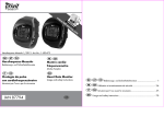
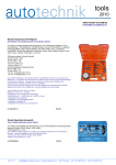
C
ol
ig
op
r
s
h
To
y
t
C
r
er
ol
ig
op
s
h
To
yr
t
C
ol
ig
op
s
L
h
yr
as
t
C
ol
ig
op
e
s
L
h
yr
as
t
C
ig
op
e
L
h
r
yr
as
t
T
ig
oo
op
e
La
ht
r
yr
T
s
ig
oo
e
La
ht
r
l
s
T
ri
s
oo
C
gh
e
L
r
ls
as
t
To
C
e
ol
op
La
r
s
T
yr
se
oo
C
i
o
La
r
ls
p
T
yr
se
oo
C
i
o
r
g
l
p
s
h
T
yr
se
t
o
C
Incorrect or out of phase engine timing can result in damage to the valves.
The Tool Connection cannot be held responsible for any damage caused
by using these tools in anyway.
3388
op
yr
Safety Precautions – Please read
engine slowly, by hand and to re-check
the camshaft and crankshaft timing
positions.
• Disconnect the battery earth leads
(check radio code is available)
• Do not use cleaning fluids on belts,
sprockets or rollers
• Crankshafts and Camshafts may only be
turned with the chain drive mechanism
fully installed.
• Always make a note of the route of the
auxiliary drive belt before removal
• Do not turn crankshaft via camshaft or
other gears
• Turn the engine in the normal direction
(clockwise unless stated otherwise)
• Check the diesel injection pump timing
after replacing the chain
• Do not turn the camshaft, crankshaft or
diesel injection pump once the timing
chain has been removed (unless
specifically stated)
• Observe all tightening torques
• Do not use the timing chain to lock the
engine when slackening or tightening
crankshaft pulley bolts
• Incorrect or out of phase engine timing can result in damage to the valves
oo
ls
C
• Remove spark or glow plugs to make
the engine turn easier
• Do not turn the crankshaft or camshaft
when the timing belt/chain has been
removed
Part No. 1870
Timing Tools Kit
for Bosch fuel
injection pumps
• Always refer to the vehicle manufacturer’s service manual or a suitable proprietary instruction book
•
It is always recommended to turn the engine slowly, by hand, and to re-check the camshaft and crankshaft timing positions
• Mark the direction of the chain before
removing
er
To
• It is always recommended to turn the
La
se
5 018341 018702
www.lasertools.co.uk
www.lasertools.co.uk
C
ol
ig
op
r
s
h
To
y
t
C
r
er
ol
ig
op
s
h
To
yr
t
C
ol
ig
op
s
L
h
yr
as
t
C
ol
ig
op
e
s
L
h
yr
as
t
C
ig
op
e
L
h
r
yr
as
t
T
ig
oo
op
e
La
ht
r
yr
T
s
ig
oo
e
La
ht
r
l
s
T
ri
s
oo
C
gh
e
L
r
ls
as
t
To
C
e
ol
op
La
r
s
T
yr
se
oo
C
i
o
La
r
ls
p
T
yr
se
oo
C
i
o
r
g
l
p
s
h
T
yr
se
t
o
C
Plan Layout
Instruction (DE)
MOTOREINSTELLWERKZEUGSATZ für
Bosch-Einspritzpumpen
Ref
Code
A
C079
M8 Adaptor Long
B
C080
Extension – 99mm long
C
C081
Thread Convertor M8-M12
D
C127
E
C128
M8 Adaptor Short
F
C129
Extension – Short 40.8mm
G
C130
M10 Adaptor - Short
La
se
er
To
oo
ls
C
op
yr
Mit diesem Werkzeugsatz kann die richtige
Motorsteuerungsstellung für Bosch VEEinspritzpumpen, wie sie von Kikki und Nippon Denso
gefertigt werden, eingestellt werden.
2
Oem Code
KM 571A
3313
Description
Dial Test Indicator 41mm x 8mm x 0.1mm
www.lasertools.co.uk
www.eldontools.
1.
Die Standard-Tastspitze der Messuhr abschrauben
und die richtige Verlängerung aufschrauben.
2.
Die kurze Verlängerung (F) wird mit dem kurzen
M8-Adapter (E) und die lange Verlängerung (C) mit
dem langen M8-Adapter (A) verwendet.
3.
Den M8-Adapter mit der richtigen Länge auswählen
und die Messuhr mit Verlängerung anbringen.
4.
Den Adapter am Messuhrschaft mit der Mutter
befestigen. Einige Einspritzpumpen haben einen
Anschluss mit M12-Gewinde.
5.
Pos. (D) kann an beide Adaptertypen montiert
werden und dient der Anpassung M8 auf M12
– (Abb. 1)
6.
Den Bereich der Einspritzpumpe um den
Wartungsanschluss reinigen.
7.
Den Verschluss herausschrauben und den Adapter
sowie die Messuhr anbringen. Die Messuhr kann
zum besseren Ablesen gedreht werden – (Abb. 2)
8.
Die Mutter am Adapter lösen, um die Messuhr mit
Verlängerung mit dem Pumpenkolben in Berührung
zu bringen. Dadurch wird die Messuhr um circa 1
mm vorgeladen.
9.
Die Mutter festziehen, damit die Messuhr nicht im
Adapter verrutscht.
10. Die Messuhr an der Einfassung nullen und mit der
Rändelschraube in dieser Stellung arretieren.
11. Die Kurbelwelle rückwärts drehen, bis der Zeiger
der Messuhr sich zu bewegen aufhört.
Kontrollieren, ob die kleine Skala des Zifferblatts
der Messuhr eine Vorlast von 1 mm anzeigt und die
Einfassung nochmals nullen.
12. Die Kurbelwelle zum statischen Zündzeitpunkt
drehen und die Anzeige der Messuhr mit den
Einstelldaten des Herstellers vergleichen.
13. Wenn die Anzeige richtig ist, die Messuhr, den
Adapter und Verlängerungen entfernen.
www.lasertools.co.uk
7
C
ol
ig
op
r
s
h
To
y
t
C
r
er
ol
ig
op
s
h
To
yr
t
C
ol
ig
op
s
L
h
yr
as
t
C
ol
ig
op
e
s
L
h
yr
as
t
C
ig
op
e
L
h
r
yr
as
t
T
ig
oo
op
e
La
ht
r
yr
T
s
ig
oo
e
La
ht
r
l
s
T
ri
s
oo
C
gh
e
L
r
ls
as
t
To
C
e
ol
op
La
r
s
T
yr
se
oo
C
i
o
La
r
ls
p
T
yr
se
oo
C
i
o
r
g
l
p
s
h
T
yr
se
t
o
C
Instruction (ES)
Applications
JUEGO DE HERRAMIENTAS DE REGLAJE para
bombas de inyección de gasolina Bosch
op
yr
Este juego le permite ajustar la posición de sincronización
correcta en bombas de combustible de tipo VE Bosch y
bombas compatibles fabricadas por Kikki y Nippon Denso.
La extensión corta (F) se utiliza con el adaptador M8
corto (E), y la extensión larga (C) se utiliza con el
adaptador M8 largo (A).
3.
Seleccione el adaptador M8 de la longitud correcta y
sujete el indicador de prueba de dial con la
extensión.
4.
Apriete el adaptador al vástago del indicador de
prueba de dial utilizando la tuerca y fíjela. Algunas
bombas tienen un puerto roscado M12.
5.
El elemento (D) puede montarse en ambos
adaptadores y convierte la rosca M8 en M12
– (Fig. 1).
6.
Limpie la bomba de inyección de combustible
alrededor del puerto de servicio.
7.
Retire el tapón y sujete el adaptador y el indicador
de prueba de dial. Puede girar el indicador de
prueba de dial para hacer que sea fácil de leer
– (Fig. 2).
8.
Afloje la tuerca en el adaptador para permitirle
llevar al indicador de prueba de dial y la extensión
en contacto con el émbolo de la bomba. Esto
pre-cargará el indicador de prueba del dial en
aproximadamente 1 mm.
To
oo
Destornille la punta estándar del indicador de
prueba de dial y fije la extensión correcta en su
lugar.
2.
ls
C
1.
er
9.
Apriete la tuerca para evitar que el indicador se
deslice en el adaptador.
10. Ponga a cero el bisel del indicador de prueba de dial
y bloquéelo en posición con el tornillo de mariposa.
11. Gire el cigüeñal hacia atrás hasta que la punta
indicadora en el indicador de prueba de dial detenga
su movimiento. Compruebe que la escala pequeña en
la cara del indicador de prueba de dial muestra una
pre-carga de 1 mm y vuelva a poner a cero el bisel.
se
12. Gire el cigüeñal hacia delante hasta el punto de
reglaje estático y compare la lectura en el indicador
de prueba de dial con los datos de reglaje
especificados del fabricante.
The application list for this product has been compiled cross referencing the OEM Tool Code
with the Component Code.
In most cases the tools are specific to this type of engine and are necessary for Cam belt or
chain maintenance.
If the engine has been identified as an interference engine valve to piston damage will
occur if the engine is run with a broken Cam belt.
A compression check of all cylinders should be performed before removing the cylinder
head.
Always consult a suitable work shop manual before attempting to change the Cam belt or
Chain.
Autodata
Our applications data is supplied by Autodata and we are able to supply this data to you in
a PDF format.
If this is a specific kit for a group of engine codes the application list has been supplied
showing the main vehicles this kit is designed for and does not list every model each pin fits.
If this is a master kit then all vehicles are included.
The data is the copyright of Tool Connection and should not be reproduced.
If the application data is extensive we have included a CD with the application list in .pdf
format.
Languages
We have also included where possible translations for the instructions in the following
languages:
• French
• Spanish
• German
• Portuguese
• Italian
• Dutch
The use of these engine timing tools is purely down to the user’s discretion and
Tool Connection cannot be held responsible for any damage caused what so ever.
ALWAYS USE A REPUTABLE WORKSHOP MANUAL
La
13. Cuando la lectura sea correcta, retire el indicador de
prueba de dial, el adaptador y cualquier extensión.
6
www.lasertools.co.uk
www.lasertools.co.uk
3
C
ol
ig
op
r
s
h
To
y
t
C
r
er
ol
ig
op
s
h
To
yr
t
C
ol
ig
op
s
L
h
yr
as
t
C
ol
ig
op
e
s
L
h
yr
as
t
C
ig
op
e
L
h
r
yr
as
t
T
ig
oo
op
e
La
ht
r
yr
T
s
ig
oo
e
La
ht
r
l
s
T
ri
s
oo
C
gh
e
L
r
ls
as
t
To
C
e
ol
op
La
r
s
T
yr
se
oo
C
i
o
La
r
ls
p
T
yr
se
oo
C
i
o
r
g
l
p
s
h
T
yr
se
t
o
C
Instruction (GB)
Instruction (FR)
KIT D’OUTIL DE CALAGE pour les pompes
à injection de carburant Bosch
This kit enables you to set the correct timing position on
Bosch VE type fuel pumps and compatible pumps
manufactured by Kikki and Nippon Denso.
Ce kit vous permet d’obtenir la position de calage correcte
sur les pompe à carburant de type Bosch VE et sur les
pompes compatibles fabriquées par Kikki et Nippon Denso.
1.
Unscrew the standard tip from the dial test
indicator and fix the correct extension in its place.
1.
Dévisser l’embout standard de l’indicateur de test à
cadran et le remplacer par une extension correcte.
2.
The short extension (F) is used with the short M8
adaptor (E), and the long extension (C) is used with
the long M8 adapter (A).
2.
L’extension courte (F) est utilisée avec l’adaptateur
court M8 (E) et l’extension longue (C) est utilisée avec
l’adaptateur long M8 (A).
3.
Select the correct length M8 adaptor and attach
the dial test indicator with extension.
3.
4.
Tighten the adaptor to the dial test indicator shank
by using the nut and secure. Some fuel pumps have
a M12 threaded port,
Sélectionner l’adaptateur M8 de la bonne longueur et
le fixer sur l’indicateur de test à cadran avec
l’extension.
4.
5.
Item (D) can be fitted to either adaptor and
converts the M8 thread to M12 – (Fig 1)
Serrer l’adaptateur sur la tige de l’indicateur de test à
cadran à l’aide de l’écrou. Certaines pompes à
carburant ont un orifice fileté M12.
5.
6.
Clean the fuel injection pump around the service
port.
Le composant (D) peut être posé sur l’un ou l’autre des
adaptateurs et convertit le filetage M8 en filetage M12
(Fig. 1).
7.
Remove the plug and attach the adapter and dial
test indicator. You can turn the dial test indicator
to make it easy to read – (Fig 2)
6.
Nettoyer la pompe à injection de carburant autour du
port de contrôle.
7.
Retirer le capuchon et poser l’adaptateur et le dispositif
de test à cadran. Vous pouvez tourner l’indicateur de
test à cadran pour faciliter la lecture (Fig. 2).
8.
10. Zero the dial test indicator bezel and lock it in
position with the thumbscrew.
Desserrer l’écrou sur l’adaptateur pour amener
l’indicateur de test à cadran et l’extension en contact
avec le plongeur de la pompe. Cela exerce une
précharge sur l’indicateur de test à cadran d’environ 1
mm.
9.
11. Turn the crankshaft backwards until the pointer on
the dial test indicator stops moving. Check that the
small scale on the face of the dial test indicator
shows a 1mm pre-load and re-zero the bezel.
Serrer l’écrou pour empêcher que l’indicateur ne
coulisse dans l’adaptateur.
10. Mettre à zéro la lunette de l’indicateur de test à
cadran et la verrouiller en position avec la vis à
serrage à main.
oo
ls
C
op
yr
TIMING TOOL KIT for Bosch fuel
injection pumps
8.
Tighten the nut to prevent the indicator sliding
within the adapter.
er
To
9.
Loosen the nut on the adapter to enable you to
bring the dial test indicator and extension into
contact with the pump plunger. This will pre-load
the dial test indicator by approximately 1mm.
12. Turn the crankshaft forward to the static timing
point and compare the reading on the dial test
indicator with the manufacturer’s specified timing
data.
La
se
13. When the reading is correct, remove the dial test
indicator, adapter and any extensions.
4
11. Tourner le vilebrequin vers l’arrière jusqu’à ce que
l’aiguille de l’indicateur de test à cadran cesse de
bouger. Vérifier que le relevé de petite taille sur la
face de l’indicateur de test à cadran indique une
précharge de 1 mm et remettre la lunette à zéro.
12. Tourner le vilebrequin vers l’avant jusqu’au point
de calage statique et comparer le relevé sur l’indicateur
de test à cadran avec les données
de calage du constructeur.
13. Si le relevé est correct, déposer l’indicateur de test à
cadran, l’adaptateur et les extensions.
www.lasertools.co.uk
www.lasertools.co.uk
5