1
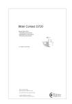
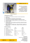
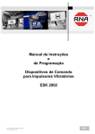
METASYS
GB
Central single unit suction
METASYS EXCOM ZA1
Installation, operation and maintenance
Contents
Key to symbols
The footnote found on each page defines the user group
particular information is aimed at.
1. Contents:
Page
1. Contents
2
2. Key to symbols
2
3. General information
3
4. Application
4
5. Construction 4
6. Key to type plates
4
7. Technical data 5
8. Method of operation
5
9. Guidelines for assembly
6
10.Hose connections
7
11. Electrical connections 8
12. Key to servicing parts
9
13. Changing the collection container
10
14.Disposal of the full container
11
15. Maintenance, cleaning and disinfection
12
16.Service mode 13
17. The annual inspection 14
18.The 5 year inspection
15
2. Key to symbols:
!
Warning that to ignore the following instructions
could lead to personal injury, disrupt operation or
damage the apparatus!
Means, that the servicing personnel or the technicians are made aware of certain facts.
Page
GB
Practice personnel / Technician
General information
3. General information:
!
METASYS can only guarantee safety, reliability
and performance of the apparatus, when the
following instructions are adhered to:
Installation, changes or repairs are carried out by authoq
rized service personnel in compliance with EN Standard
60601-1 (International Standard for Medical Electrical
Apparatus, especially Part 1: General Rules for Safety).
The electrical installation complies with the IEC (Internaq
tional Commission for Electrical Engineering) regulations.
The apparatus is assembled, operated and maintained
q
according to the instructions provided.
Only original parts are used for repairs or replacements.
q
All the guidelines provided by the manufacturer on the
q
correct use of the amalgam separator COMPACT Dynamic
are followed.
A
fter commissioning, the Installation Proof found
into the Equipment Logbook must be completed
and returned to METASYS in order to determine the
guarantee period.
Every inspection, servicing and exchange of collection
q
container should be recorded in the Equipment Logbook.
By law, every amalgam waste disposal certificate should
q
be kept.
When requested by an authorized engineer, METASYS
q
agrees to make all documents available for the use of
technically qualified service personnel.
METASYS accepts no responsibility for damages caused
q
due to external factors, such as wrong installation,
improper use of the apparatus or unauthorized technical
intervention.
Duplication and distribution of this document may only
q
be undertaken after a prior permission is obtained from
METASYS.
When the complete amalgam separator has been disq
mantled at the end of its working life, it must be returned
to the manufacturer for disposal.
Practice personnel / Technician
GB
Page
Use, construction
Explanation of the type plate
4. Use:
The METASYS EXCOM ZA1 is a single unit dry suction system with integrated air/water separation, amalgam separation and place selection valve in combination with a suction
engine.
1.5
5. Construction:
1.3
1.1
In order to allow quick and easy replacement of individual
parts for service and repair, the suction system EXCOM ZA1
consists of several modules:
1
See illustration
1.1
METASYS COMPACT Dynamic
METASYS COMPACT Dynamic with collection container, separation unit, centrifuge, main frame of the amalgam separator, electronic circuit board as well as place selection valve.
1.2
1.4
!
Must only be opened by qualified specialists!
The control box contains the terminals for the electrical connections and the control board.
1.2
1.3
1
Condensate separator with air by-pass valve
The condensate separator collects any condensation that
might form in the suction pipe upstream from the suction
engine. The air by-pass valve limits the vacuum and protects
the suction engine against overheating.
1.4
Un = 230V, 50/60 Hz
ZA1 - 00076
Pmax = 0,55 / 0,65 kw
960
VH2O max = 4,5 l/min
p max = 160 bar *
*reguliert / pre installed
2.2
2.1
METASYS Medizintechnik GmbH
A-6063 Rum bei Innsbruck, Florianistr. 3
2.3
2.4
2.5
Made in Austria TK 2005-16
EXCOM ZA1
Mounting plate with fittings
The mounting plate serves as a fastening for the different
modules. The tube connections can also be found on it.
1.5
Suction engine
The suction engine uses the side channel compression principle.
6. Explanation of the type plate:
2
See figure
The type plate is located on the mounting plate of the
COMPACT Dynamic.
2
Control box
Page
2.1
Name of the equipment
2.2
Connection data
2.3
Serial number
2.4
Manufacturer’s address
2.5
CE mark
GB
Practice personnel / Technician
Technical data
Method of operation
7. Technical data:
3
Suction unit EXCOM ZA1
Power supply:
230 V AC
Frequency:
50/60 Hz
Max. current consumption:
5,9 A/5,5 A
Max. electrical shaft power:
0,55 KW / 0,65 KW
Low pressure range:
160 mbar (regulated)
Flow rate:
400 l/min
Max. water flow rate:
4,5 l/min
Separation rate:
96,4 %
Collection container volume:
300 cm3
Permissible ambient temperature: + 5 °C to + 40 °C
Permissible atmospheric humidity
(motor room):
0 bis 95 %
Protection class:
IP 21
Weight:
26 kg
Dimensions (l x w x h) mm:
540 x 400 x 400
3
8. Functional description:
4
See illustration
After operating the main switch of the COMPACT Dynamic a test
run is carried out. If a signal is audible at the external display,
consult the Service Manual to find the cause of the error and its
troubleshooting. If no signal is audible, the device is ready for
operation.
4.1
4.2
When lifting a suction tube the COMPACT Dynamic amalgam
separator 4.1 is activated. Afterwards, with a delay of approx.
1 second, the suction engine 4.2 and the place selection
valve is triggered. A prefilter 4.3 , integrated in the ZA1, collects coarse particles from the intake flow, before the air is fed
into the COMPACT Dynamic amalgam separator. In the separation, the intake flow's solid and fluid components are tangentially centrifuged, while the air is directed to the suction engine
via the separation impeller's rotor shafts. The cleaned water is
drained at the outlet 4.4 , the solid parts are discharged into
the collection container.
The waste water from the spittoon bowl is directly discharged
into the collection container 4.5 (cf. Service Manual COMPACT Dynamic amalgam separator). After hanging up the suction
tube both the non-return place selection valve and the suction
engine are switched off. Following a certain after-run time the
engine of the COMPACT Dynamic also stops.
Practice personnel / Technician
GB
4.3
4.4
4.5
4
Page
Installation guidelines
9. Installation guideline:
T
he EXCOM ZA1 suction system is designed to be
q
installed only in dry, adequately ventilated rooms.
T heir use in areas subject to explosive and fire
hazards is not permitted.
!
The permitted room temperature ranges from between
q
+10°C and + 40°C. The relative humidity must not exceed
70%.
I
nstallation can be on the same level as the treatment
q
units, in a side room or one floor lower.
In order to avoid vibrations, the suction system
must be installed on a firm base.
15 cm
See illustration
1
W
hen the EXCOM ZA1 suction system is installed, the
q
connection side must be placed at least 15 cm from the
wall so that the hoses can be connected.
1
T
he front of the device must be easily accessible. If the
q
EXCOM ZA1 system is installed with the covering hood,
the device must not be covered or have objects placed
on top of it. To allow the removal of the covering hood,
a free space above equal to the equipment's height and
equal to half its width at the sides. There must be clear
space of approx. 5 cm around the device to guarantee
adequate air circulation.
Prefilter:
2.1
Prefilter already installed
Air inlet valve:
To ensure a complete flush of all material, liquid and particles, even when the suction tube is on, an air inlet valve
needs to be installed into the unit furthest away from the
central unit.
Pipe and hose installation:
2.1
!
Any pipe or hose used must be resistant to all chemicals normally used in a dental practice (e.g. HT discharge pipes made from PP, PVC-C, PVC-U, PE-HD)
2
Page
GB
Technician
Practice personnel
/ Technician
Installation guidelines
Hose connections
Only flexible spiral hoses made from PVC or equivalent
q
materials may be used.
Connections to the EXCOM ZA1 central suction system must
q
be made by flexible hoses and be as short as possible.
3.3
3.2
We recommend a pipe diameters of 32 mm to avoid rightq
angle bends in order not to lose suction power (recommendation: 2 x 45º degree bends).
Discharge pipes must meet applicable local legislation
q
or DIN 1986, Parts 1 and 2.
Waste water must be allowed to drain off freely without
q
any backup. Waste water pipes must have a hydraulic
gradient of at least 2%.
The air must be discharged out-of-doors. For reasons of
q
hygiene and in order to avoid noise pollution we recommend that the outgoing air connection is fitted with a
bio-filter.
The rinsing of the spittoon bowl needs to be limited to max.
q
30 seconds of max. 3l/min by means of a push-button or
timing relay, in order to allow the centrifuge to stop.
10. Hose connections:
3
3.4
See illustration
3.1
Connection for spittoon drainage hose
i.d. = 15/26 mm
3.2
Connection for suction hose (to suction tube holder)
i.d. = 26/26 mm
3.3
Connection exhaust air - suction engine
o.d. = 15/26 mm
3.4
Connection for drainage pipe (clean water outlet)
o.d. = 15/16 mm
3.1
3
The distance between the EXCOM ZA1, the unit and the suction tube holder must not exceed 15 m.
We recommend:
for the water connections METASYS PVC dental tube
q
for the air connections METASYS PVC suction tube
q
A
ll hose connections must be secured with hose
clamps!
Not required water connections must be closed
with the provided blank plugs!
!
Practice personnel
/ Technician
Technician
GB
Page
Electrical connections
11. Electrical connections
Mains connection:
The mains connection must only be carried out by a trained
electricians.
The electrical installation must be carried out in accordance
with applicable local regulations.
Before connecting to the mains, the nominal voltage stated
on the type plate on the equipment must be compared with
the mains voltage.
The EXCOM ZA1 suction system must only be connected to
the power supply with the supplied power cable. Extension
cables must not be used.
Main switch:
1
K2 K1
In order to allow self-diagnosis, the EXCOM ZA1 suction system must be switched off at least once per working day.
W2
Connection to the mains must be established after the practise's main switch.
V1
W3
S1
W1
W4
W5
T1
2
X10
D14
2 2.3
24 V
X3
X4
MOT
X2
X8
+MV
+FA
X6
X9
2.1
X5
LIS
2.4
3
2.7
Page
2.6
2.5
2.9
2.8
2.10
Control unit EXCOM ZA1
Motor contactor
K2
Timing relay
M1
Motor for VAC
S1
Main switch
T1
Transformer
V1
Varistor
W1
Power supply
W2
Motor cable
W3
Sucking contact
W4
Power supply 24 V C COMPACT Dynamic
W5
Starting COMPACT Dynamic
Connections mainboard of COMPACT Dynamic
3
X7
S1
Wiring diagram EXCOM ZA1
2
K1
2.11
2.2
1
2.1
D14 L ED Net (illuminated when the power supply is on)
2.2
S1
Fuse T 6,3 A (replace with an identical part only!)
2.3
X3
Power supply 24 V AC
2.4
X2
Motor connection (internal)
2.5
X6 Interferring signal output to the unit
2.6
X8 Suction current - external
2.7
X7
Suction holder signal
(24 V AC when suction hose is removed)
2.8
X5
Connection for the measurement of filling-height
2.9
X4 Connection for the external control unit
2.10
X9 Connection for the capacitive sensor
2.11
X10 Terminal for the processor
GB
Technician
Practice personnel
/ Technician
Control unit
12. Key to control unit:
4.1
To survey the EXCOM ZA1 an additional external display can
be installed in the treatment room.
4.2
4.3
See diagram
4
4.1
Control light 1: Ready for operation
Green illuminated: confirms that the unit is switched on
q
4.2
Control light 2: Centrifuge error
Flashing red and audible buzzer signal: Error!
q
See diagram
4.3
5
- Error messages
RESET
Control light 3: Container full
Y
ellow illuminated and audible buzzer signal, which
q
can be turned off through RESET: the collection container is 95% full:
It is recommended that the collection container be replaced;
however, it is possible to continue operation until the container is 100% full. As a reminder, the control lamp remains
illuminated and every time the unit is switched on, the buzzer signal is activated.
4.4
4
= leuchten = permanent = allumé
= rimane accesa
= encendido Yellow light illuminated and audible buzzer signal,
q
which can not be turned off through RESET: the collector container is 100% full:
The collection container must be replaced immediately! It
is not possible to continue working, as the place selection
valve gets blocked.
4.4
= blinken
= flashing
= intermittent
= lampeggiare
= intermitente
Alarm- RESET- button
T
he buzzer can be turned off by pressing the red RESET
q
button, when the 95% full message is displayed, or when
an error is reported.
5
5.1
RESET
Error messages (see diagram)
S
ignal 1 green illuminated, signal 2 flashing red,
audible buzzer signal control: error in the electronic
system!
5.1
The buzzer is turned off by pressing the RESET-button. In
this case, the main switch is first switched off, and after a
short pause (approx. 5 sec.), switched back on. If the control
lamps light again after a short time, please call upon your
servicing engineer!
5.2
Signal 2 flashing red, audible buzzer signal:
collection container has not been installed correctly!
RESET
The buzzer can not be turned off, no other signal illuminates.
Please proceed as described in chapter 13, for the correct
installation of the collection container.
5.2
5
Practice personnel / Technician
GB
Page
Changing the collection container
13. Changing the collection container:
Switch off the main switch of the EXCOM ZA1 unit!
q
Keep a new collection container ready, and remove the
q
disinfectant bag!
Wear protective gloves!
q
1
Lift the locking bracket of the amalgam separator,
holding the separator firmly.
2
1
2
Pull the amalgam separator forwards out from the
fixing unit, and place on an even and non-slip surface.
3
Hold the collection container firmly, and twist the top
anti-clockwise, till the marking under the locking
bracket and the yellow marking on the collection
container come into alignment. Pull the top off
upwards.
2
4
1
If the pump filter is soiled, pull it out, clean over a
drip tray, and place back onto the suction end of the
pump housing.
4
3
5
Fit the top onto a new collection container in such a
manner, that the yellow marking on the collection
container and the yellow marking under the locking
bracket come into alignment.
Fix the collection container and twist the top clockwise, as far as it will go; check visually (all the supporting clips of the container must be properly
locked into place).
1
5
6
2
VASELINE
6
5
Grease the seal on the supporting element using
Vaseline.
7
Carefully insert the amalgam separator into its support, and close the locking bracket.
Switch the main switch of EXCOM ZA1 unit on!
q
If the collection container has been installed correctly, then
the amalgam separator runs for a brief period, and then the
external display indicates "Ready for operation" (Signal 1
illuminated green).
If the collection container has not been installed correctly, then
signal 2 starts flashing on the external display, and a buzzing
sound is heard. In this case, switch the main switch off, and
carefully repeat the procedure mentioned above (in pt. 5 & 7).
1
2
7
10
Page
GB
Practice personnel / Technician
Disposal of the full collection container
with Dental Eco Service
14. Disposal of the full collection container:
Wear protective gloves, and possibly a mask! Avoid
contact with the contents of the collection container!
!
The collection container is, for technical and hygienic reasons, destined for single use only!
Reuse of the soiled container can lead to technical problems
and will invalidate the warranty!
The filled collection container must be sent to the METASYS
Group subsidiary Recycling company D ental ECO S ervice
GmbH! By law, a confirmation of disposal should be given
and retained.
When the whole amalgam separator is dismantled at the end
of its operational life, it must be returned to the manufacturer, for its orderly disposal.
8
9
The simplest method of disposal is by using ECOTransform:
8
See diagram
Cut one corner of the disinfectant bag (this is enclosed with
the new container) and empty it into the full collection container for the disinfection.
9
See diagram
Close the full container using the green lid (provided with
the new container), by twisting it clockwise.
Check if the lid is fully closed by holding the closed container
upside down over a drip pan (if required, re-tighten the lid).
10
10
See diagram
Place the closed collection container inside the Styroporshells of the transport box.
Seal off the transport carton as per the handling instructions
enclosed.
11
See diagram
Label package with enclosed return label and send to Dental
ECO Service GmbH.
11
12
See diagram
Empty any amalgam residues from the preliminary filters
into the special collection container (METASYS ECOC enter )
and subject to the same to proper disposal.
Operating the amalgam separator without the preliminary
filter is not allowed, do not suck in residues from the preliminary filter!
12
Practice personnel / Technician
GB
Page
11
Maintenance, cleaning and disinfection
with Green&Clean M2
15. Maintenance, cleaning and disinfection:
1
See diagram
Shortly flush spittoon bowl after each treachment!
2
See diagram
Suck some water through all suction hoses after every treatment.
3
2
1
See diagram
Twice daily, after the water has been drained off, the specifically designated disinfectant Green&Clean M2 has to be used.
This treatment with the disinfectant Green&Clean M2 must
ideally be done prior to long periods of non-use, such as
before lunch breaks, after work, or before holidays.
4
See diagram
Also flush spittoon with Green&Clean M2 twice a
day and additionally clean with the cuspidor cleaner
Green&Clean MB.
Cleaning the preliminary filter:
q
The preliminary filter must be emptied and cleaned at least
once a week. Depending on your working patterns, you may
even carry out this cleaning daily.
3
5
See diagram:
The residues emptied from the filter box containing amalgam, should be collected into an appropriate container
(METASYS ECOCenter), and sent for a proper disposal to
Dental ECO Service.
4
5
12
Page
GB
Practice personnel / Technician
Service mode
16. Service mode
The COMPACT Dynamic amalgam separator electronics allow
the equipment’s functions to be checked using a service
mode.
When switching the main switch on, press the RESET
button on the operating component for at least 5 seconds.
6
PUSH 5sec
= leuchten = permanent = allumé
= rimane accesa
= encendido Signal 1 (ready for operation) flashes at twice its normal
†
frequency (25 Hz)
6.2
6.2
6.1
Entering the service mode
6
6.1
RESET
RESET
IMPORTANT! In order to enter normal operation or service mode after the equipment has
been switched off, wait at least 5 seconds before
switching it on again!
As soon as signal 1 flashes, release the RESET button
= blinken
= flashing
= intermittent
= lampeggiare
= intermitente
† Signal 1 flashes very rapidly (25 Hz)
Press the RESET button briefly to start the motor
q
The motor is stopped by pressing once again
q
In case of a malfunction of the motor monitoring system (shortcircuit monitoring and monitoring of the running of the motor)
the electronic systems will not allow the motor to start.
RESET
RESET
The motor can be switched on and off at will by briefly
q
7
pressing the RESET button
8
Pressing the RESET button for approximately 5 seconds
q
will change the service mode from motor monitoring to
testing the inlets and outlets. (Release the RESET button
after hearing a beep)
Signal 1 flashes; signals 2 and 3 are steadily illuminated
q
Procedure for testing the inlets and outlets – see Point 17 of
“Annual Inspection.”
RESET
RESET
Press the RESET button once again for approximately 4
q
seconds to end the service mode
† Signal 3 flashes (25 Hz)
The equipment switches from service to normal operation
9
const.
const.
10
† Signal 1 is permanently on
7 - 12 Please contact your service engineer if the following malfunction messages appear:
7
Malfunction in the short-circuit monitoring
8
Malfunction in the monitoring of the running of the motor
9
Motor malfunction on starting
10
Current consumption of the motor when running is too high
11
Power supply to motor interrupted
12
Short-circuit of motor power supply
Practice personnel / Technician
11
GB
RESET
RESET
const.
2,5Hz
12
Page
13
Annual inspection
17. The annual inspection:
According to the German Institute of Construction
Technology, the display elements of the amalgam
separator have to be tested at least once every
year by an authorized technician.
Recall the service mode, as described under point 16
q
Conduct a test run of the motor at least once
q
Continue for the checking of the inlet and outlet
q
Signal 1 flashes, signal 2 and 3 remain permanently lit
†
Remove the separator from the supports
q
Simulation of the display units
See diagram
1
C
over only the lower light-barrier of the filling-height
measurement
Signals 1 and 3 flash, signal 2 remains permanently lit
†
1.1
C
over only the upper light-barrier of the filling-height
measurement
Signals 1 and 2 flash, signal 3 remains permanently lit
†
1.2
C
over both the light-barriers of the filling-height
measurement
Signals 1, 2 and 3 flash
†
1.2
1.3
1.1
1.3
1
Re-fix the separator into the supports
q
See diagram
2
2.1
2.2
2.1
2.1
P
ress button to rinse spittoon bowl
W
ater level rises up to the switching point of the
capacitive sensor
Buzzer sounds
†
Lift up a suction hose (= activate SV7-Signal)
q
Magnetic valve closes (passage of suction-current)
q
Hook the suction pipe back in its holder
q
To terminate the service mode, keep the RESET button
q
pressed again
Signal 3 flashes
†
Signal 3 flashes (25Hz). The instrument changes over
†
2.2
from the service to normal mode
Signal 1 remains permanently lit
†
During the annual inspection, we recommend a prophylactic
replacement of the following parts by an authorized technician: amalgam collection container, sealing unit, separation
rotor, pump-filter.
Data from the annual inspection must be entered into the
Equipment Logbook!
2
14
Page
GB
Technician
Practice personnel
/ Technician
5 year inspection
18. The 5 year inspection:
3.1
3.1
In accordance with the German Waste Management Regulations, amalgam separators must be
examined at intervals of no longer than 5 years.
Conduct the annual inspection, as described in chapter 17
q
C heck whether the amalgam separator is correctly
q
mounted and connected.
3.2
Not only rinse the suction hose, but also the basin with
q
a minimum of 1 liter clean water and the specifically
designated disinfectant Green&Clean M2.
3
!
Visual check of the centrifuge:
3.8
Wear protective gloves!
Switch the main switch off!
3.3
3.4
3.5
Remove the separator from the wall-mounting bracket
q
3.1 Remove the four screws on top of the device using a
Torx 20
3.2
Remove the lid of the separator
(use the screw-driver at the backside)
3.6
Do not remove the inlet-sealing of the separator!
q
3.3 Remove the separation rotor; for this, remove the
!
plug at the center of the rotor using pointed pliers,
loosen the internal hex nut and pull the rotor out,
upwards. (ATTENTION: left-handed threads!)
3.4
Pull off the pump hose at the back of the separator to
the upper connection
3.5
3.6
3.9
3.7
Pull off the centrifuge's inlet upwards
Lift the centrifuge chambers upwards
Carry out a visual check of the centrifuge chambers for contamination; centrifuge chambers, which show excessive
signs of coatings or sedimentation of solid materials, must
be replaced!
Finally, reassemble in the reverse order
q
Attention! Make sure the 4 pins 3.7 are inserted in the
holes provided on the bottom of centrifugal chamber. Also,
the square of the Sepa rotor 3.8 must click-fit into the
centrifuge's upper side 3.9 .
It is important that all screws are fixed and screwed in as far
as they go.
Data from the 5 year inspection must be entered into the
Equipment Logbook!
3
Practice personnel
/ Technician
Technician
GB
Page
15
METASYS
Austria
METASYS
Medizintechnik GmbH
Florianistraße 3
A-6063 Rum bei Innsbruck
1+43/(0)512 /20 54 20-0
5 +43/(0)512/20 54 20-7
www.metasys.com
Italy
Dental ECO Service Italia S.r.l.
Florianistraße 3
A-6063 Rum bei Innsbruck
1 +39/045/981 4477
5 +39/045/981 4475
e-mail: [email protected]
Ihr METASYS Berater:/Your METASYS agent:
ZK-55.243/01
email: [email protected]
70100327
France
METASYS France S.a.r.l.
9, bd E. Michelet
F-69008 Lyon
1+33/(0)4/37 90 22 15
5 +33/(0)4/37 90 22 47
e-mail: [email protected]
www.metasys.fr
EBW Saugsystem EXCOM ZA1 englisch, 26.02.2010
METASYS
Medizintechnik GmbH
Ahornstraße 19
D-85614 Kirchseeon
1+49/(0)2236 / 37 42 42
5 +49/(0)2236 / 37 42 41
Subject to technical changes, printing and setting errors
Germany