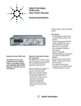
1
S Agilent E8311/12A 165/330 MHz Pulse and Pattern Generators Installation Guide S1 Notice Copyright Agilent Technologies 1999, 2000. All rights reserved. No part of this manual may be reproduced in any form or by any means (including electronic storage and retrieval or translation into a foreign language) without prior agreement and written consent from Agilent Technologies Inc. as governed by United States and international copyright laws. Notice The material contained in this document is subject to change without notice. Agilent Technologies makes no warranty of any kind with regard to this material, including, but not limited to, the implied warranties of merchantability and fitness for a particular purpose. Agilent Technologies shall not be liable for errors contained herein or for incidental or consequential damages in connection with the furnishing, performance, or use of this material. Warranty This Agilent Technologies product has a warranty against defects in material and workmanship for a period of three years from date of shipment. During the warranty period, Agilent Technologies will, at its option, either repair or replace products that prove to be defective. For warranty service or repair, this product must be returned to a service facility designated by Agilent Technologies. The Buyer shall pay Agilent Technologies round-trip travel expenses. For products returned to Agilent Technologies for warranty service, the Buyer shall prepay shipping charges to Agilent Technologies and Agilent Technologies shall pay shipping charges to return the product to the Buyer. However, the Buyer shall pay all shipping charges, duties and taxes for products returned to Agilent Technologies from another country. Agilent Technologies warrants that its software and firmware designated by Agilent Technologies for use with an instrument will execute its programming instructions when properly installed on that instrument. Agilent Technologies does not warrant that the operation of the instrument software, or firmware, will be uninterrupted or error free. Certification Do Not Remove the Instrument Cover Agilent Technologies certifies that this product met its published specifications at the time of shipment. Agilent Technologies further certifies that its calibration measurements are traceable to the United States Institute of Standards and Technology, to the extent allowed by the Institute's calibrating facility, and to the calibration facilities of other International Standards Organization members. Operating personnel must not remove instrument covers. Component replacement and internal adjustments must be made only by qualified service personnel. Services and Support Instruments that appear damaged or defective should be made inoperative and secured against unintended operation until they can be repaired by qualified service personnel. Safety Symbols Any adjustment, maintenance, or repair of this product must be performed by qualified personnel. Contact your customer engineer through your local Agilent Technologies Service Center. You can find a list of local service representatives on the Web at: http://www.agilent.com/Service/English/index.html Caution (refer to accompanying documents) Safety Summary The following general safety precautions must be observed during all phases of operation of this instrument. Failure to comply with these precautions or with specific warnings elsewhere in this manual violates safety standards of design, manufacture, and intended use of the instrument. Agilent Technologies Inc. assumes no liability for the customer's failure to comply with these requirements. General This product is a Safety Class 1 instrument (provided with a protective earth terminal). The protective features of this product may be impaired if it is used in a manner not specified in the operation instructions. All Light Emitting Diodes (LEDs) used in this product are Class 1 LEDs as per IEC 60825-1. Environmental Conditions This instrument is intended for indoor use in an installation category II, pollution degree 2 environment. It is designed to operate at a maximum relative humidity of 95% and at altitudes of up to 2000 meters. Refer to the specifications tables for the ac mains voltage requirements and ambient operating temperature range. Protective earth (ground) terminal In the manuals: WA RN I N G Warnings call attention to a procedure, practice, or the like, which, if not correctly performed or adhered to, could result in personal injury or loss of life. Do not proceed beyond a Warning until the indicated conditions are fully understood and met. CA U T I O N Cautions call attention to a procedure, practice, or the like, which, if not correctly performed or adhered to, could result in damage to or destruction of part or all of the equipment. Do not proceed beyond a Caution until the indicated conditions are fully understood and met. Limitation of Warranty The foregoing warranty shall not apply to defects resulting from improper or inadequate maintenance by the Buyer, Buyer-supplied software or interfacing, unauthorized modification or misuse, operation outside of the environmental specifications for the product, or improper site preparation or maintenance. No other warranty is expressed or implied. Agilent Technologies specifically disclaims the implied warranties of merchantability and fitness for a particular purpose. Exclusive Remedies The remedies supplied are the Buyer's sole and exclusive remedies. Agilent Technologies shall not be liable for any direct, indirect, special, incidental, or consequential damages, whether based on contract, tort or any other legal theory. Before Applying Power Verify that the product is set to match the available line voltage, the correct fuse is installed, and all safety precautions are taken. Note the instrument's external markings described under “Safety Symbols” on page 8. Ground the Instrument To minimize shock hazard, the instrument chassis and cover must be connected to an electrical protective earth ground. The instrument must be connected to the ac power mains through a grounded power cable, with the ground wire firmly connected to an electrical ground (safety ground) at the power outlet. Any interruption of the protective (grounding) conductor or disconnection of the protective earth terminal will cause a potential shock hazard that could result in personal injury. Fuses Only fuses with the required rated current, voltage, and specified type (normal blow, time delay, etc.) should be used. Do not use repaired fuses or short-circuited fuse holders. To do so could cause a shock or fire hazard. Do Not Operate in an Explosive Atmosphere Do not operate the instrument in the presence of flammable gases or fumes. Agilent E8311/12A 165/330 MHz Pulse and Pattern Generators, April 2000 Contents Contents Introducing the Agilent E8311/12A Pulse and Pattern Generators 5 What You Can Do with the Agilent E8311/12A 6 Basic Features Automated Testing The Front Panels Front Panel Agilent E8311A Front Panel Agilent E8312A Inputs and Outputs LEDs on the Front Panel Installing the Agilent E8311/12A Selecting a Mainframe Slot Setting Logical Addresses of the VXI Instruments Installing the Instrument in the Mainframe Installing the Software Agilent E8311/12A 165/330 MHz Pulse and Pattern Generators, April 2000 6 6 7 7 8 9 10 11 12 13 14 15 3 Contents 4 Agilent E8311/12A 165/330 MHz Pulse and Pattern Generators, April 2000 Introducing the Agilent E8311/12A Pulse and Pattern Generators The purpose of this introductory chapter is to give a general overview of the Agilent E8311A and Agilent E8312A VXI instruments. The main features and methods of use are described in “What You Can Do with the Agilent E8311/12A” on page 6. The front panels with their inputs and outputs are depicted and described in “The Front Panels” on page 7. For detailed information on how to program the instruments, please refer to the Quick Start Guide (pdf file). To view or print this manual, open the Windows Start menu and select Programs – Vxipnp – Agilent E8311/12A – Quick Start Guide. Agilent E8311/12A 165/330 MHz Pulse and Pattern Generators, April 2000 5 Introducing the Agilent E8311/12A Pulse and Pattern Generators What You Can Do with the Agilent E8311/12A What You Can Do with the Agilent E8311/12A This section introduces the basic features and methods of use of the Agilent E8311A VXI instrument. Reference is made to the differences between the Agilent E8311A and the Agilent E8312A instruments. Basic Features The Pulse and Pattern Generators generate all the standard pulses and digital patterns needed to test all current logic technologies (for example, TTL, CMOS, ECL, PECL, LVDS, GTL) and other digital designs up to 165 MHz with the Agilent E8311A instrument and up to 330 MHz with the Agilent E8312A instrument. The instruments feature two internal oscillators: • a synchronously triggerable internal oscillator • an accurate, stable internal PLL For even more accuracy, an external frequency reference can be connected. The instruments provide a reliable and wide range of signals. Any timing parameter can be varied without glitch and drop out. This contributes to more accurate and reliable characterizations of the device under test (DUT). With the Agilent E8311A the output channels can be used separately or be added to form complex signals such as multi-level waveforms (analog channel add). Automated Testing Using the VXIplug&play driver commands, the new product can be easily integrated into all phases of test-system development such as planning rack integration and test program generation. These benefits combined with the low cost of ownership make the Agilent E8311/12A an invaluable instrument for a wide range of technical applications. 6 Agilent E8311/12A 165/330 MHz Pulse and Pattern Generators, April 2000 The Front Panels Introducing the Agilent E8311/12A Pulse and Pattern Generators The Front Panels This section shows the front panels of both Agilent E8311A and E8312A instruments and describes their input and output connectors. Front Panel Agilent E8311A The following figure shows the front panel of the Agilent E8311A with its input and output connectors. Agilent E8311/12A 165/330 MHz Pulse and Pattern Generators, April 2000 7 Introducing the Agilent E8311/12A Pulse and Pattern Generators The Front Panels Front Panel Agilent E8312A The following figure shows the front panel of the Agilent E8312A with its input and output connectors. 8 Agilent E8311/12A 165/330 MHz Pulse and Pattern Generators, April 2000 The Front Panels Introducing the Agilent E8311/12A Pulse and Pattern Generators Inputs and Outputs The major inputs and outputs of the instruments Agilent E8311A and Agilent E8312A are: (For more details, please refer to “Using the Agilent E8311/12A” in the Quick Start Guide.) • EXTERNAL IN Can be used to connect an external arming source (triggered or gated modes) and to generate leading and trailing edges (external width mode). • CLOCK/REF IN Can be used to connect either an external clock signal or a reference signal for the internal PLL if a higher frequency accuracy than 0.01% is required. • STROBE OUT Is used only in burst and in pattern mode. – In burst mode the strobe output rises at the start of the first pulse period and falls at the start of the last pulse period. – In pattern mode the strobe output can be programmed for each bit. You can set the output levels to TTL or ECL. • TRIGGER OUT Marks the start of each pulse period. You can set the output levels to TTL or ECL. • OUTPUT – Agilent E8311A: The output connectors provide the normal signal output for channel 1 and channel 2. – Agilent E8312A: The output connectors provide the normal and inverted signal outputs for channel 1 and channel 2. Agilent E8311/12A 165/330 MHz Pulse and Pattern Generators, April 2000 9 Introducing the Agilent E8311/12A Pulse and Pattern Generators The Front Panels LEDs on the Front Panel The LEDs on the front panel are: • “Failed” LED This red LED is lit during module initialization. If it does not turn off after initialization, please contact your local Agilent support center. • “Access” LED This green LED flashes while the module is accessed by the controller. NOTE If the “Access” LED flashes continuously, for example, flash–flash–flash, pause, flash–flash–flash, pause and so on, please record this error code (number of continuous flashes) and contact your local Agilent support center. • LEDs at the outputs These green LEDs show the current state of the outputs (on or off). 10 Agilent E8311/12A 165/330 MHz Pulse and Pattern Generators, April 2000 Installing the Agilent E8311/12A The Agiilent E8311/12A are VXI instruments that plug into a VXI mainframe. Installing the instruments requires the following steps: 1 “Selecting a Mainframe Slot” on page 12 2 “Setting Logical Addresses of the VXI Instruments” on page 13 3 “Installing the Instrument in the Mainframe” on page 14 4 “Installing the Software” on page 15 Agilent E8311/12A 165/330 MHz Pulse and Pattern Generators, April 2000 11 Installing the Agilent E8311/12A Selecting a Mainframe Slot Selecting a Mainframe Slot The first step to install a VXI instrument is to select a free slot in the VXI mainframe. When you have selected a slot, enter the instrument model number, name, and serial number for the instrument in the VXI Mainframe Overview table. You should maintain such a table for each mainframe in order to keep track of the installed instruments. Slot Model Number Instrument Name Logical Address Serial Number 0 1 2 3 4 5 6 7 8 9 10 11 12 12 Agilent E8311/12A 165/330 MHz Pulse and Pattern Generators, April 2000 Setting Logical Addresses of the VXI Instruments Installing the Agilent E8311/12A Setting Logical Addresses of the VXI Instruments When you have selected the slot for the VXI instrument, the next step is to set the instrument logical address (LADDR) as required. You can generally use the factory-set (default) logical address. If you need to set another logical address, use the following guidelines (see the applicable Mainframe User’s/Service Manual for more information). The logical address for each VXI instrument is set by the Logical Address (LADDR) switch on the instrument. The logical address value is the sum of the values of the logical address switches set to the closed position. The following figure shows the defaults for the Agilent E8311A (LADDR 111) and the Agilent E8312A (LADDR 112): 0 1 7 6 5 4 3 2 1 0 0 0 1 1 Address Switches set to 111 0 7 6 5 4 3 2 1 0 1 Address Switches set to 112 After setting the address switches, record the logical address in the VXI Mainframe Overview table. Agilent E8311/12A 165/330 MHz Pulse and Pattern Generators, April 2000 13 Installing the Agilent E8311/12A Installing the Instrument in the Mainframe Installing the Instrument in the Mainframe After setting the logical address as required, you can then install the instrument in the mainframe. 1 Turn mainframe power off. 2 Install the instrument in the slot you previously identified. 3 Turn mainframe power on. W AR N IN G In operation the side covers of the instrument may become very hot. Therefore be very careful when you remove the VXI instruments from the mainframe. C A U T I ON Do not touch the connectors on the rear side of the instruments to protect against electrostatic discharge to the instruments. 14 Agilent E8311/12A 165/330 MHz Pulse and Pattern Generators, April 2000 Installing the Software Installing the Agilent E8311/12A Installing the Software The Agilent 81100 Graphical User Interface and the VXIplug&play drivers must be installed on the control PC. Depending on the system configuration, this may either be an external PC or a PC embedded in the VXI mainframe. NOTE Before installing the software make sure that the I/O Libraries for Instrument Control are already installed on the control PC. 1 If required, connect a CD-ROM drive to the PC. 2 Insert the CD labeled “Agilent 81100 Pulse/Data Generator Family” (Part No. E8311-10020) into the CD-ROM drive. 3 The installer starts automatically when the CD is inserted. If it does not, open the Explorer, select the CD-ROM drive, and run \Setup.exe. 4 Then follow the instructions on screen: – Choose the destination folder. – Select the program folder VXIPNP. – Select the components you want to install. Agilent E8311/12A 165/330 MHz Pulse and Pattern Generators, April 2000 15 Installing the Agilent E8311/12A 16 Installing the Software Agilent E8311/12A 165/330 MHz Pulse and Pattern Generators, April 2000 Copyright Agilent Technologies 1999, 2000 Edition 1.0, E0400 Printed in Germany April 2000 E8311-91020 S1