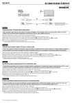
1
SERVICE MANUAL
MODEL : LG-200
LG-200
SERVICE MANUAL
Table Of Contents
1. PERFORMANCE ..................................................... 2
1-1.
1-2.
1.3.
1-4.
1-5.
1-6.
1-7.
HW Features ........................................................... 2
Memory Requirment ............................................... 2
Technical Specification ........................................... 3
GSM band RF Specifications ................................. 7
DCS band RF Specifications .................................. 8
Receiver (GSM) ...................................................... 9
Receiver (DCS) ...................................................... 9
2. TECHNICAL BRIEF .............................................. 10
2-1.
2-2.
2-3.
2-4.
2-5.
2-6.
2-7.
2-8.
2-9.
Receiver ............................................................... 10
Transmitter ........................................................... 14
The PA Circuit and its Control .............................. 17
13 MHz Clock ....................................................... 18
Main Processor and DSP ..................................... 19
Power Supplies and Control Signals .................... 21
User Interface Board ............................................ 28
Testing Set-up and Checking Signals .................. 32
Dimensions of Main Components. ........................ 43
3. TROUBLE SHOOTING ....................................... 53
3-1.
3-2.
3-3.
3-4.
3-5.
Power Supply Failure ........................................... 53
Voice Function Failure .......................................... 55
Display Function Failure ........................................ 55
Transmission & Receiving Failure ........................ 57
Other Function Failure ........................................... 57
4. TEST POINT DATA ............................................... 60
5. ASSEMBLY INSTRUCTIONS ........................... 68
6. BLOCK DIAGRAM ............................................... 73
7. CIRCUIT DIAGRAM ............................................. 74
8. HOW TO DOWNLOAD S/W .............................. 83
9. HOW TO PROCESS CALIBRATION ............... 84
10. EXPLODED VIEW .............................................. 90
11. REPLACEMENT PARTS LIST......................... 91
-1-
1. PERFORMANCE
1-1. HW Features
Item
Battery
AVG TCVR current(mA)
Stand by current(mA)
- Talk time
- Stand by time
- Charging time
RX sensitivity
TX output power
GPRS compatibility
SIM card type
Display
Status Indicator
ANT
Ear Phone Jack
PC synchronization
Speech coding
Data & Fax
Vibrator
Melody(for Buzzer Function)
Voice Recording
C-Mike
Receiver
Speaker Phone
Portable Handsfree
Travel Adapter
Options
Feature
Li-Ion Battery, 600mAh
Size
: 105.9x44.8x19.7mm
Weight : 89g, 77cc
PCB
: M/B:99.5x38.3;K/B:99.5x39.4mm
GSM Imax(390mA),DCS Imax(320mA)
≤ 5mA
2.5-hour (GSM Tx Level_7)
85-hour(Paging Period:2 RSSI:-85dBm)
1.5-hour
GSM:-107dBm, DCS:-104dBm
GSM (Level 5:33dBm), DCS (Level0: 30dBm)
N/A
3v/5v small
128x64
Soft Icons
Keypad : 0-9, #, *, C, P/book, up/down, on/off
External
System connector : N/A
Yes
N/A
Memory : 1MB
EFR/FR
N/A
Yes
22
N/A
N/A
Yes
N/A
Yes, option
Yes
Comment
Switching
1-2. Memory Requirment
Application
GSM Protocol
WAP (AUR Browser)
Zi ezText (2 Languages at
the same time)
ART
Voice Memo (3 Minutes)
Phone Book
Voice Tag
Game & Accessory
GPRS
RAM Size
120KB
N/A
N/A
ROM Size
880KB
N/A
N/A
N/A
N/A
1KB
N/A
3K
N/A
N/A
N/A
2KB
N/A
20K
N/A
-2-
1. PERFORMANCE
1-3. Technical Specification
Item
1
Description
Frequency Band
Specification
GSM900 band
Tx : 890 + n*0.2 MHz
Rx : 935 + n*0.2 MHz
(n = 1 ~ 124)
GSM1800 band
Tx : 1710 + (n-512)*0.2
Rx : 1805 + (n-512)*0.2
(n = 512 ~ 885)
2
Phase error
RMS < 5 degrees
Peak < 20 degrees
3
Frequency error
< 0.1ppm : = 90 Hz (for GSM900) or 180 Hz (for GSM1800)
5
Power Level
GSM900
Control Level
Power Level
Tolerance
5
6
7
8
9
10
11
12
13
14
15
16
17
18
19
33 dBm
31 dBm
29 dBm
27 dBm
25 dBm
23 dBm
21 dBm
19 dBm
17 dBm
15 dBm
13 dBm
11 dBm
9 dBm
7 dBm
5 dBm
± 2dB
± 3dB
± 3dB
± 3dB
± 3dB
± 3dB
± 3dB
± 3dB
± 3dB
± 3dB
± 3dB
± 5dB
± 5dB
± 5dB
± 5dB
GSM1800
Control Level
Power Level
Tolerance
0
1
2
3
4
5
6
7
8
9
10
11
12
13
14
15
30 dBm
28 dBm
26 dBm
24 dBm
22 dBm
20 dBm
18 dBm
16 dBm
14 dBm
12 dBm
10 dBm
8 dBm
6 dBm
4 dBm
2 dBm
0 dBm
2dB
± 3dB
± 3dB
± 3dB
± 3dB
± 3dB
± 3dB
± 3dB
± 3dB
± 4dB
± 4dB
± 4dB
± 4dB
± 4dB
± 5dB
± 5dB
-3-
Item
6
Description
Specification
Spectrum due
to modulation
GSM900
Offset from Carrier(KHz).
Max. dBc
100
200
250
400
600 ~ <1200
1200 ~ <1800
1800 ~ <3000
3000 ~ <6000
≥ 6000
+0.5
-30
-33
-60
-60
-60
-63
-65
-71
GSM1800
7
Spectrum due to
switching transient
Offset from Carrier(KHz).
Max. dBc
100
200
250
400
600 ~ <1200
1200 ~ <1800
1800 ~ <3000
3000 ~ <6000
≥ 6000
+0.5
-30
-33
-60
-60
-60
-65
-65
-73
GSM900
Offset from Carrier(KHz).
Max. dBc(KHz).
400
600
1200
1800
-19
-21
-21
-24
GSM1800
Offset from Carrier(KHz).
Max. dBc
400
600
1200
1800
-22
-24
-24
-27
8
Spurious emissions
Conduction, Emission Status, Appendix 1
Conduction, Emission Status, Appendix 2
9
Bit Error Rate
GSM900
BER(Class II) <2.439% @-102dBm
DCS1800
BER(Class II) <2.439% @-100dBm
-4-
1. PERFORMANCE
Item
10
Description
Rx Level Report accuracy
Specification
GSM900
GSM1800
≥ -88
≥ -101
< -101
≥ -86
≥ -99
< -99
11
SLR
8 ± 3 dB
12
Sending Response
Frequency (Hz)
RLR
14
Receiving Response
2
2
2
Max.(dB)
Min.(dB)
-12
0
0
0
4
4
4
0
/
/
-12
-6
-6
-6
-9
/
Frequency (Hz)
Max.(dB)
Min.(dB)
100
200
300
500
1,000
3,000
3,400
4,000
-12
0
2
*
0
2
2
2
/
/
-7
-5
-5
-5
-10
/
100
200
300
1,000
2,000
3,000
3,400
4,000
13
2
3
4
2 ± 3 dB
* Mean that Adopt a straight line in between 300Hz& 1,000Hz
to be Max. level in the range.
15
STMR
13 ± 5 dB
16
Stability Margin
> 6 dB
17
Distortion
dB to ARL (dB)
Level Ratio (dB)
-35
-30
-20
-10
0
7
10
17.5
22.5
30.7
33.3
33.7
31.7
25.5
18
Sidetone Distortion
Three stage distortion < 10%
19
<Change> System frequency
(13MHz) tolerance
≤ 2.5ppm
20
<Change>32.768KHz
tolerance
≤ 30ppm
-5-
Item
21
Description
Power consumption
Specification
Full power: < 390mA (GSM) ; < 320mA (DCS)
Standby : 1. Normal ’≤ 5mA(Mix. power)
2. Using Test mode on DSP Sleep function ≤ 6mA
22
Talk time
GSM/ Level_7 (Battery Capacity 650mA): 130Min
GSM/ Level_7 (Battery Capacity 600mA): 120Min
23
Standby time
Under conditions, at least 85 hours:
1. Brand new and full 600mAh battery
2. Full charge, no receive/send and keep GSM in idle mode.
3. Broadcast set off.
4. Signal strength display set at 3 level above.
5. Backlight of phone set off.
24
Ringer Volume
At least 70dB under below conditions:
1. Ringer set as ringer 7.
2. Test distance set as 50 cm
25
Charge Voltage
Fast Charge: < 600 mA
Slow Charge: < 100 mA
26
Antenna display
GSM
≥ -84dBm
≥ -89dBm
≥ -94dBm
≥ -101dBm
≥ -105dBm
Tolerance: ± 2 dB
DCS
-80dBm : 4
-85dBm : 3
-90dBm : 2
-97dBm : 1
-101dBm : 0
27
Battery indicator
Level
0
1
2
3
4
Tolerance: ± 0.1V
Voltage (v)
V ≤ 3.5V
3.5 ≤ V ≤ 3.7
3.7 ≤ V ≤ 3.8
3.8 ≤ V ≤ 4.0
4.0 ≤ V
28
Low Voltage Warning
3.5V ± 0.1V
29
Forced shut down Voltage
3.3V ± 0.1V
30
Battery Type
1 Li-Ion battery
Standard Voltage = 3.7V
Battery full charge voltage =4.2V
Capacity: 650mAh/600mAh (Li-Ion);
31
Travel Charger
Linear Charger
In put: 110V or 240 VAC, 50/60Hz
Out put: 5VDC ± 0.25V, 500mA (No Load)
Switching-mode charger
In put: 96- 246VAC, 50/60Hz
Out put: 5VDC ± 0.25V, 500mA (No Load)
-6-
1. PERFORMANCE
1-4. GSM band RF Specifications
Frequency Stability
< ± 90Hz
RF Maximum Power Output
RF Output Power Levels
Power Control Level 5
Power Control Level 6
Power Control Level 7
Power Control Level 8
Power Control Level 9
Power Control Level 10
Power Control Level 11
Power Control Level 12
Power Control Level 13
Power Control Level 14
Power Control Level 15
Power Control Level 16
Power Control Level 17
Power Control Level 18
Power Control Level 19
33dBm
15, decrementing in 2dB steps
33dBm ± 2dB
31dBm ± 3dB
29dBm ± 3dB
27dBm ± 3dB
25dBm ± 3dB
23dBm ± 3dB
21dBm ± 3dB
19dBm ± 3dB
17dBm ± 3dB
15dBm ± 3dB
13dBm ± 3dB
11dBm ± 5dB
9dBm ± 5dB
7dBm ± 5dB
5dBm ± 5dB
TX Frequency Output
Low Channel (Ch 1)
Mid Channel (Ch 62)
High Channel (Ch 124)
TX Frequency Calculation (Ftx)
890.2 MHz
902.4 MHz
914.8 MHz
890 + (ARFCN x 0.2) = Ftx MHz
TX UHF VCO Frequency
Low Channel (Ch 1)
Mid Channel (Ch 62)
High Channel (Ch 124)
TX UHF VCO Freq. Calculation (Ftuhf)
1160.2 MHz
1172.4 MHz
1184.8 MHz
Ftx + 270 = Ftuhf MHz
IF VCO Frequency
540 MHz
TX IF Frequency
Rx IF Frequency
270 MHz
270MHz
Phase Error
Peak Phase Error
RMS Phase Error
< 20 degrees
< 5 degrees
-7-
1-5. DCS band RF Specifications
Frequency Stability
< ± 180Hz
RF Maximum Power Output
RF Output Power Levels
Power Control Level 0
Power Control Level 1
Power Control Level 2
Power Control Level 3
Power Control Level 4
Power Control Level 5
Power Control Level 6
Power Control Level 7
Power Control Level 8
Power Control Level 9
Power Control Level 10
Power Control Level 11
Power Control Level 12
Power Control Level 13
Power Control Level 14
Power Control Level 15
30dBm
16, decrementing in 2dB steps
30dBm ± 2dB
28dBm ± 3dB
26dBm ± 3dB
24dBm ± 3dB
22dBm ± 3dB
20dBm ± 3dB
18dBm ± 3dB
16dBm ± 3dB
14dBm ± 4dB
12dBm ± 4dB
10dBm ± 4dB
8dBm ± 4dB
6dBm ± 4dB
4dBm ± 4dB
2dBm ± 5dB
0dBm ± 5dB
TX Frequency Output
Low Channel (Ch 512)
Mid Channel (Ch 699)
High Channel (Ch 885)
TX Frequency Calculation (Ftx)
1710.2 MHz
1747.6 MHz
1784.8 MHz
1710.2 + (ARFCN x 0.2) = Ftx MHz
TX UHF VCO Frequency
Low Channel (Ch 1)
Mid Channel (Ch 62)
High Channel (Ch 124)
TX UHF VCO Freq. Calculation (Ftuhf)
1530.2 MHz
1567.6 MHz
1604.8 MHz
Ftx + 180 = Ftuhf MHz
IF VCO Frequency
540 MHz
TX IF Frequency
Rx IF Frequency
180 MHz
270MHz
Phase Error
Peak Phase Error
RMS Phase Error
< 20 degrees
< 5 degrees
-8-
1. PERFORMANCE
1-6. Receiver (GSM)
RX Frequency Input
Low Channel (Ch 1)
Mid Channel (Ch 62)
High Channel (Ch 124)
RX Frequency Calculation (Frx)
935.2 MHz
947.4 MHz
959.8 MHz
935 + (ARFCN x 0.2) = Frx MHz
RX UHF VCO Frequency
Low Channel (Ch 1)
Mid Channel (Ch 62)
High Channel (Ch 124)
RX UHF VCO Freq. Calculation
(Fruhf)
1160-1230 MHz
1205.2 MHz
1217.4 MHz
1229.8 MHz
Frx + 270 = Fruhf MHz
RX VCO Frequency
Demodulation Frequency
IF Frequency
BER (Bit Error Ratio)
540 MHz
270 MHz (540/ 2)
270 MHz
Type II BER <2.4% at -102dBm
Type II BER <0.1% at -15dBm
1-7. Receiver (DCS)
RX Frequency Input
Low Channel (Ch 1)
Mid Channel (Ch 62)
High Channel (Ch 124)
RX Frequency Calculation (Frx)
1805.2 MHz
1842.6 MHz
1879.8 MHz
Ftx + 95 Mhz = Frx MHz
1535-1610 MHz
RX UHF VCO Frequency
Low Channel (Ch 1)
Mid Channel (Ch 62)
High Channel (Ch 124)
RX UHF VCO Freq. Calculation (Fruhf)
RX VCO Frequency
Demodulation Frequency
IF Frequency
BER (Bit Error Ratio)
1535.2MHz
1572.6 MHz
1609.8 MHz
Frx - 270 = Fruhf MHz
540 MHz
270 MHz (540/ 2)
270 MHz
Type II BER <2.4% at -102dBm
Type II BER <0.1% at -15dBm
-9-
2. TECHNICAL BRIEF
2-1. Receiver
1. The front end
The RF receive signal (GSM 935Mhz - 960MHz, DCS 1805Mhz - 1880Mhz) is input via the antenna or
coaxial connector. An antenna matching circuit is between the antenna and the connector.
The diplexer U23 is used to control the Rx and Tx paths. And the input signal RX_TX_B of pin 2 of Q19
is connected to U1(SC1688) to switch either Rx or Tx path on. When the Rx path is turned on, the RF
receives signal then feeds into two paths, Rx_1800_RF and Rx_900_RF.
This Rx_1800_RF path contains one SAW filter U46 to filter any unwanted signal apart from the DCS
Rx band. And the U45 in the Rx_900_RF path is to filter out unwanted signal beyond the GSM Rx
band. These two paths are then connected to the DLNAI (# 2) and GLNAI(# 4) of W3020(U31)
respectively.
The RF receive signal is amplified by LNAs in W3020 with the output at DLNAO (# 63) and GLNAO (#
61) respectively, and then pass through the SAW filters B4635 (U22) and B4684 (U10). After this
filtering process, the signal then feeds into U31 for mixing with LO, which is produced by the
synthesiser W3000 (U19), and two VCOs.
In W3020, UHF mixers produce a IF signal of frequency 270 MHz at RMON (# 51) and RMOP (# 50) in
differential mode. This differential signal is filtered by B4836 (U50), a 270 MHz SAW filter, and then fed
to W3020 #34 and #35.
- 10 -
2. TECHNICAL BRIEF
2. RX I&Q Demodulator
The modulated IF signal is demodulated by mixing with a 270 MHz signal, which was derived from the
540Mhz oscillator. Before the mixer is a 32db gain IF amplifier which can be set to either 0 or 32db of
gain. The mixer has 6db gain itself, and then followed by two low-pass filters and five baseband
amplifiers.
The W3020 produces demodulated baseband signals at RIP (# 47), RIN (# 46), RQP(# 45) and RQN(#
44) which are connected to SC1688(U1) .
- 11 -
3. UHF Synthesizer (Rx)
The synthesizer for RX and TX UHF are implemented by W3000 (U19). The outputs of DCS VCO
(1530 ~ 1610 MHz) and GSM VCO (1160 ~ 1230 MHz) are fed to U19 #5 for phase comparison in
order to generate the charge pump output U19 #2 to control the frequency of VCOs. On the locked
state, the frequency of VCO is
Fvco=[(P*M)+A] * fref / R
Where
Fref is the frequency of the signal on U19 #10. Here is 13 MHz.
P, M, A, R are all constants set by the three-wired digital control bus:
DATA #13
LATCH #14
CLOCK #12
The loop filter between U19 #2 and VCO #5 converts the current signal on U19 #2 to the voltage signal
on VCO #5.
Q15 is a switch, which controls the power supply of VCOs.
- 12 -
2. TECHNICAL BRIEF
4. The Rx IF Synthesiser
The major part of Rx IF synthesiser is built in W3020 including a phase comparator, and a charge
pump, etc. Outside the W3020, the C164 and R189 and C225 form the loop filter; Q31 is a power
switch and the VCO would be locked at 540 MHz.
In the W3020, this 540 MHz signal is divided by 2 for the receiver, divided by 2 for the GSM Tx and
divided by 3 for the DCS Tx.
- 13 -
2-2. Transmitter
[The TX IF Modulator in W3020]
1. The TX IF Modulator
The TX I & Q signals from U1 #86-89 are fed to #38-41 of the W3020 TX modulator (U31), where they
are then modulated onto either a TX IF of 270Mhz (for GSM-TX) or 180Mhz (for DCS-TX) by the
quadrature-mixer inside U31.
The signal TX LO IF (180-270Mhz) is input from U31. This signal is produced by the external 540Mhz
oscillator (U42), which has been divided down by a factor of 2 for GSM-TX or 3 for DCS-TX. This
division factor is set by the control signal of U31 #28-30. The TX modulated IF signal of 180/270Mhz is
output on #52-53 of U31 for GSM/DCS.
2. The TX IF Synthesizer
The second local oscillator (LO2), comprising a buffer for the external voltage-controlled oscillator
(VCO) and a phase-locked loop (PLL), feeds the IF portions of both the modulator and the receiver. An
external reference source, voltage-controlled crystal oscillator (VCXO), is divided from 13 MHz to 1
MHz through a counter. The 1 MHz is called the comparison frequency. The VCO(U42) frequency of
540 MHz is also divided down to 1 MHz. Both signals are fed into a phase detector, and the resultant
error signal is fed through an external low-pass filter to the control input of the VCO (U42).
- 14 -
2. TECHNICAL BRIEF
[The UHF Mixer/Amplifier/TX UHF Synthesiser]
3. The UHF Mixer Amplifier
The modulated TX IF signal GSM (270Mhz) or DCS(180Mhz) is mixed onto the GSM(890Mhz-915Mhz)
or DCS(1710Mhz-1785Mhz) TX RF frequency. This is achieved by mixing the TX IF signal with the TX
UHF VCO output from U30 for GSM and U29 for DCS. Hence:
GSM TX = UHF VCO - 270 ie, (1160 - 270 = 890Mhz)
DCS TX = UHF VCO +180 ie, (1530 + 180 = 1710 Mhz)
The modulated RF signal is then output on #59-60 to a BPF and then enters the UPC2771TB (U3/U43)
at #1. The RF modulated signal is then amplified by the Pre-driver with the UPC2771TB IC.
The RF signal is then output on #4 of the UPC2771TB and passed through another stage of filtering
(BPF: U4/U44).
- 15 -
4. The TX UHF Synthesizer
In TX mode the TX UHF VCO output is fed to #5 (U19) and then pre-scaled down to 200khz. The
phase comparator within U19 compares this signal with a 200khz signal derived from the 13Mhz clock
(U35) and outputs a current phase difference at #2. A loop filter then converts this signal into a voltage
phase difference and feeds it to #5 (U29) or (U30). The voltage phase difference determines the UHF
VCO frequency i.e. GSM TX 1160Mhz -1185Mhz, DCS TX 1530Mhz - 1610Mhz. Three control inputs
are used in the UHF Synthesiser SERDA, SERCK, SERLT. It is the SERDA control input, which initially
sets the TX VCO frequency. This is totally dependent on the chosen traffic channel the logic circuit has
selected at the time.
[The Power Amp Circuit]
5. The PA Circuit
The power amplifier control circuit ensures that the RF signal is regulated to the required limits of
operation. The TX RF signal is input on #3(U9) or (U32) and the power amplifier outputs the signal at
#10. The diplexor is tuned to the GSM or PCN duplex spacing so enabling selectivity between GSM
and PCN Rx or Tx.
- 16 -
2. TECHNICAL BRIEF
2-3. The PA Circuit and its Control
1. The PA Circuit and its Control
The power amplifier control circuit ensures that the RF signal is regulated to the required limits of
operation.
Power-control is carried out according to the measurement of the power-output of the P.A. (RF_Detect,
see Fig.: P.A Circuit Control). A voltage drop, which is converted from the RF power through a DiodeDetector, is then integrated by the operational amplifier (U21) to give an error voltage regulates the
TXP signal.
The TXP input signal to the power control circuit is generated by the U1 #90. TXP provides a limit for
the frequency spectrum caused by burst modulation.
VDD_TXBUF (2.85V) is the main power supply for power control circuit. An op-amp, U21, which
outputs a control signal, but is not enough to drive the P.A. to the maximum output. Q20 and Q26 are
an extra amplifier and buffer stage that use Vbat (more than 3.5V) in order to drive the control signal to
a sufficient level for P.A.
The power control circuitry has two different loop gains for increasing the dynamic power control range
and it is switched by U54 that is controlled by the control supply, PCL_SW.
The control supplies, PA_900_EN_B and PA_1800_EN_B control the switches Q28 and Q29 to make
sure the control signal goes to the right PA, VRAMP_900 and VRAMP_1800.
- 17 -
2-4. 13 MHz Clock
The 13 MHz-clock (END3352B) consists of a TCXO (Temperature Compensated Crystal Oscillator)
which oscillates at a frequency of 13MHz.
It's used within the W3000 Synthesizers, Communication Protocol processor (CPP), and Super Chip 1
(SC1689).
NC7S04 buffer the output to CPP, SC1 and W3000.
- 18 -
2. TECHNICAL BRIEF
2-5. Main Processor and DSP
1. Main Processor CPP-C
The CPP-C is a Lucent Technologies designed processor. The CPP-C performs the following
functions:
• CPU
• CPU Interface
• Interrupt Controller
• Baseband Power Control
• Keypad Control
• Display Interface
• Buzzer Control
• UART Control/Interface
• I/O System Connector Interface
• Battery Voltage Monitoring
• Charge Control
• Real Time Clock
• CPU Timers
• Backlight Control
• Vibrator Control
[System Block Diagram of CPP-C]
- 19 -
2. DSP and Mixed Signal Processor SC1689
Designed specifically for GSM cellular systems, the SC1689 (Super Chip 1) processor of Lucent
Technologies is a mixed-signal device that is based on the DSP1600 core with a bit manipulation unit
(BMU), error correction processor (ECCP), and conversion signal processor (CSP) core.
The CSP consists of a baseband, voice band, and digital audio interface to fulfill the GSM requirement
for a voice band and baseband interface.
The device peripheral combination consists of a serial port, parallel host interface, and two timers. The
device (IROM0 and IROM1) switchable via ROMMUX in the ioc register.
[System Block Diagram of SC1689]
- 20 -
2. TECHNICAL BRIEF
3. CPU Memories
Flash ROM
An 8Mbit programmable ROM is capable of being written while being still in circuit. Contains all the
main command software for the mobile.
SRAM
A 128Kbit by 8 temporary memory device, which is used by CPP-C for CPU execution.
2-6. Power Supplies and Control Signals
There are five regulators used in the phone: U24, U25, U26, U27 and U59. Those regulators are
dedicated power supplies, which provides most of the power requirements for the logic and RF circuits.
Each of these regulators can be controlled by individual enable signals. These are configured as the
following figure and table.
Regulator
Voltage
Powers
Enable Signal
Regulator 1
U24 VDD-CPP
2.85V ± 0.5
CPP-2 digital
circuitry, LCD
SHTDMN-B
Regulator 2
U25 VDD-SC1
2.85 ± 0.5
SC1 digital circuitry
SHTDMN-B
Regulator 3
U26 VDD-RF
2.85 ± 0.5
RF circuitry
RF-REG-EN
Regulator 4
U27 VDD-TXBUF
2.85 ± 1.5
Transmit power control
RF-REG-EN
Regulator 5
U59 VDD-OSC
2.9 ± 0.04V
VCO
XOEN-SC1 OR
XOEN-CPP
[Table - Power Supply]
- 21 -
[Power supply]
- 22 -
2. TECHNICAL BRIEF
1. System Reset
The R.C reset circuit generates a reset signal (active low) to the CPP-2 (SYS-RESET-B #77). when it
detects that the VDD-DIG-ERROR-B active (Regulator 1,2 voltage is below the threshold of 2.85V0.5%) The device also reset CPP-2, this then holds the CPP-2 in reset mode, allowing only the real
time clock to run.
[Reset Circuit]
2. Power On/Off
Power switch is formed by U39, Q5-2. The phone can be switched on either by pressing the power key
or connect to charger/ carkit, where PWR_SWITCH_B or CARKIT_DECTECT_B is pulled to low and
SHTDN_B, which controls the on/off of regulators, becomes high. The whole power system is thus
turned on. If either one of those two signal is kept low for one second, the PWR_KEEP signal will be
asserted to high by CPP. This realize "soft on" power key.
During switching off, if power key has been pressed more than one second then PWR_KEEP will be
released by CPP. This shuts down the power system.
[Power On/Off Control Circuit]
- 23 -
3. Battery Charge Control
Charge control is composed of Q1, D1 D8-1, D8-2, Q4-2, Q5-1 and Q33. Charge control software
controls the on/off of CHARGE-EN, which allows charge current to go through Q1-1 to battery cell. As
the battery is fully charged, CHARGE-EN becomes low to stop fast charging.
When the phone is off and the charger is plugged in, D7-3, Q4-1, and U38-6 form an auto-power-on
circuit to turn on the phone..
[Battery Charge Control Circuit]
- 24 -
2. TECHNICAL BRIEF
4. Real-Time Clock
The real-time clock is driven by a 32.768 kHz clock from a crystal oscillator. The input clock is divided
by 32,768 to generate a clock with a 1 second period that increase a 29-bit seconds counter. In
addition, it can generate interrupts at a programmed time. The following are the features of RTC:
• 17-year time interval with 1-second resolution.
• Interruption of programmed time alarm
The real-time clock consists of a seconds counter. The input clock frequency to the RTC must be
32.768 kHz. The seconds counter is updated using a clock generated by dividing the external input
clock to the RTC by 32,768.
The real-time clock assumes an interrupted power supply VRTC. The BSW signal is used by CPP to
force internal inputs to the real-time clock to appropriate levels in order to ensure correct functionality
and reduce power dissipation. When BSW =1,VRTC is connected to primary power, VDD. When BSW =0,
VRTC is supplied by backup power. The real-time clock function is specially designed to handle the
situation where VDD to the CPP is between 0 V and 2.7 V. It's the responsibility of the external logic to
the select either the normal power supply or a backup battery to provide uninterrupted VRTC.
Switching to backup power has to be done in the following sequence:
The BSW should be asserted.
Switch VRTC to backup power.
Turn off VDD and maintain VRTC.
Switching back to primary power has to be done in the following sequence:
Turn on VDD.
Switch VRTC back to primary power.
The BSW signal is deserted.
- 25 -
5. Vibrator
The vibrator is driven by the signal VIBRATOR_EN, which is output from U58 (74VHC273). The signal
is amplified by the transistor Q10 (2SC2411K) and is supplied from Vbat.
- 26 -
2. TECHNICAL BRIEF
6. Battery Voltage and Temperature Sensing
The CPP can monitor the state of the battery through the battery interface connector J6. This can be
done during both normal and charging operations. The battery provides a number of interface
connections that enable the CPP determine the battery type, its capacity, temperature and whether it is
possible to re-charge the cell(s). The thermister in the battery pack which is attached to the battery
connector (pin3) is used to produce an analogue reading of the board's own surface temperature. The
J6 connector provides a connection between the battery power contacts Vbat/GND to the main board
and BATT_TEMP_TYPE monitoring circuits to the battery.
BATT_VOLTS enables the CPP (pin59) to measure the battery voltage and hence determine how
much charge remains in the cells.
The battery pack includes an internal thermister, which is used to produce the analogue signal
BATT_TEMP_TYPE. This enables the CPP and external charger to determine the battery type and
battery temperature, which is used to protect the battery from overheating while charging.
- 27 -
2-7. User Interface Board
1. Keypad Switches and Scanning
The key switches are metal domes, which make contact between two concentric pads on the top layer
of the PCB when pressed. There are 18 switches (S1-18), connected in a matrix of 3 rows by 6
columns, as the figure shown above except for the power switch (S18), which is connected
independently. Functions, the row and column lines of the keypad are connected to ports of
CPP. The rows are outputs with 10k ohms pull-down resistors, while the columns are inputs. When a
key is pressed, the corresponding row and column are connected together, causing the row output to
go high and generate an interrupt. The columns/rows are then scanned by CPP to identify the pressed
key.
- 28 -
2. TECHNICAL BRIEF
2. Display and Interface
Power to the LCD is controlled by CPP and can be switched on and off via SYS_RESET_B. A high on
this output powers the LCD; a low switches it off. There is also the control output LCD_CS1 that is also
derived from CPP, this acts as the chip select enable for the LCD module. CPP uses MDOSDI pin to
send serial data for displaying graphical text onto the LCD
- 29 -
3. Microphone
The microphone is mounted in the handset front cover and connects to User Interface Board. The
audio signal is passed to User Interface Board and to the MICIN (#4) pin of SC1689. The voltage
supply VREG is output from SC1689 #3, and is a bias voltage for both the MICP (through R8) and
EXT_IN lines. The microphone or EXT_IN signal is then A/D converted by the CSP part of Super-chip
SC1689. The digitized speech is then passed to the DSP section of SC1689 for processing (coding,
interleaving etc.).
4. Earpiece
The earpiece is driven directly from SC1689 AOUTAP (#94) and AOUTAN(#93) pins and the gain is
controlled by the DSP software. The earpiece is located in the handset front panel, and the signals are
routed to it via two connection pads between User Interface Board and earpiece .
- 30 -
2. TECHNICAL BRIEF
5. Hands-free Interface
The audio out (AOUTBP & AOUTBN) to the hands-free kit consists of a pair of differential signals from
SC1689 auxiliary outputs (#95-96), which are tracked down the board to carkit connector (J5) at the
base of the handset.
The audio in (AUXIN) from the hands-free is converted to a single signal using the op-amp. The bias
voltage VREF from SC1689 #3 is used as a reference voltage for this amplifier. The DC level of the
signal is supplied to the AUXOUT pin. And the EXT_IN signal is then input to the AUXIN (#99) of
SC1689.
6. Buzzer Driver
The buzzer is a piezo-electric transducer, which is driven by a pulse-width- square wave from the
PWM1 output of CPP. Q901 and Q903 amplify the signal in order to achieve the specified loudness.
- 31 -
7. Back-light Illumination
In Back-light illumination, there are 10 green LEDs (six for keys and four for the LCD) in User interface
Board, which are driven by BACKLIGHT_EN line from CPP.
2-8. Testing Set-up and Checking Signals
1. Receiver RF Levels and Checks
This section shows the typical RF levels expected throughout the receiver path. A block diagram
showing the locations of the RF measurement points and levels is shown in Figure1.
2. Receiver Testing Set-up
To check the receiver the following conditions have to be set:
1. On a signal generator or a GSM/DCS test box, output a CW signal of amplitude = -40dBm at either:
947.4MHz (CH62) when testing the GSM Rx path or 1842.6MHz (CH699) when testing the DCS Rx
path.
2. Set the DC power supply to 3.8volts.
Note : All RF values shown are only intended as a guide figure and may differ from readings taken with
other test equipment and leads. Lead and connector losses should always be taken into account
when performing such RF measurements.
- 32 -
2. TECHNICAL BRIEF
3. Testing Receiver
Using a suitable high frequency probe measure the RF levels at the relevant points shown in Figure1
and compare your measurements with those shown in the diagram. If there are any major differences
between the readings taken and those indicated then further investigation of that particular point will be
required. It will also be necessary to ensure that all the following power supplies and signals are
present which control this part of the receiver circuit:
1. The Control Signal of Diplexer (see Figure 6)
2. VDD_CPP (see Figure 7)
3. VDD_SC1 (see Figure 8)
4. VDD_OCS (see Figure 9)
5. VDD_RF (see Figure 11)
6. TCXO (System Clock, see Figure 15)
4. Transmitter RF Levels and Checks
This section shows the typical RF levels expected throughout the transmitter path. A block diagram
showing the locations of the RF measurement points is shown in Figure 2.
5. Transmitter Testing Set-up
To check the transmitter the following conditions have to be set:
1. Set the DC power supply to 3.8 volts.
2. Power up the GSM/DCS test set and then establishing a call with an attached mobile on active
mode.
3. Select Channel, Tx Level and Input Level according to which parameter is required.
6. Testing the Transmitter
Using a suitable high frequency probe measure the RF levels at the relevant points shown in Figure 2
and compare your measurements with those shown in the diagram. If there are any major differences
between the readings taken and those indicated then further investigation of that particular point will be
required. It will also be necessary to ensure that all the following power supplies and signals are
present which control this part of the transmitter circuit:
1. The Control Signal of Diplexer (see Figure 6)
2. VDD_SC1 (see Figure 8)
3. VDD_OCS (see Figure 10)
4. VDD_RF (see Figure 12)
5. VDD_Tx_BUF (see Figure 14)
6. TCXO (System Clock, see Figure 15)
- 33 -
■ Receiver RF Levels
• DCS: Ch.699, -40dBm
• GSM: Ch.62, -40dBm
[Figure 1. Receiver Block Diagram]
- 34 -
2. TECHNICAL BRIEF
■ Transmitter RF Levels
• GSM: Pwr Lvl 11, Ch.62, 21dBm
• DCS: Pwr Lvl 5, Ch.699, 20dBm
[Figure 2. Transmitter Block Diagram]
- 35 -
[Figure 3. Diplexer_Circuit]
[Figure 4. System Clock]
- 36 -
2. TECHNICAL BRIEF
[Figure 5. Power_Supply_Circuit]
- 37 -
[Figure 6. The control signal of Diplexer (see Fig.3)]
[Figure 7. VDD_CPP (see Fig.5)]
- 38 -
2. TECHNICAL BRIEF
[Figure 8. VDD_SC1 (see Fig.5)]
[Figure 9. VDD_OSC (the Tx is unable) (see Fig.5)]
- 39 -
[Figure 10. VDD_OSC (the Tx is enable) (see Fig.5)]
[Figure 11. VDD_RF (the Tx is unable) (see Fig.5)]
- 40 -
2. TECHNICAL BRIEF
[Figure 12. VDD_RF (the Tx is enable) (see Fig.5)]
[Figure 13. VDD_Tx_BUF (the Tx is unable) (see Fig.5)]
- 41 -
[Figure 14. VDD_Tx_BUF (the Tx is enable) (see Fig.5)]
[Figure 15. TCXO (13MHz_RF) (see Fig.4)]
- 42 -
2. TECHNICAL BRIEF
2-9. Dimensions of Main Components.
• BZX84_C4V3 D1
[Voltage regulator diodes]
• IMN10 D7 D8 D9
[Ultra high speed switching diode array]
- 43 -
• BAT62-07W D5
[Silicon Schottky Diode]
• LM4041CIM3-1.2 D6
[Precision Micropower Shunt Voltage Reference]
- 44 -
2. TECHNICAL BRIEF
• BSS138 Q30
[SIPMOS Small-Signal Transistor]
• BCR400W U40
[Active Bias Controller]
- 45 -
• UMX1N Q5 Q28
[General purpose transistor]
• UMH11N Q27
[General purpose (dual digital transistors)]
- 46 -
2. TECHNICAL BRIEF
• Si6923DQ Q1
[P-Ch 2.5-V (G-S) MOSFET With Schottky Diode]
• UMB10N Q15
[General purpose (dual digital transistors)]
- 47 -
• Si2301DS Q21 Q22
[P-Channel 1.25-W, 2.5-V MOSFET]
• UMA3N Q29
[Emitter common (dual digital transistors)]
- 48 -
2. TECHNICAL BRIEF
• 2SA1576A Q33
[General Purpose Transistor]
• DTA123JUA Q31
[Digital transistors (built-in resistors)]
- 49 -
[CPP U15]
[SC1689 U1]
- 50 -
2. TECHNICAL BRIEF
[W3020-ES3 U31]
[W3000-ES3 U19]
- 51 -
[UCVE1X114A U42]
- 52 -
3. TROUBLE SHOOTING
3. TROUBLE SHOOTING
3-1. Power Supply Failure
a) Failure:
- Problem with turning on Mobile phone.
➜ Solution:
1. Test the set's current by using battery
simulator; observe the value of current
used.
2. Case1:
C333
If the current is higher 300mA, please
check C333. Or replace C333 if its
resistance between 2Ω and 150Ω.
3. Case 2:
- In case the current is between 35 and
45mA, the cause could be FLASH
ROM (U12) defect. Please reinstall
software.
- If the software can't be reinstalled,
please replace U12.
b) Failure:
- Problem with charging the battery
U12
- Charge connector damage
➜ Solution:
- J5 may be broken, replace the connector,
J5.
- Control the temperature and air flow
carefully.
- J5 may be a cold soldering. Please resolder again.
J5
- 53 -
c) Failure/Solution:
- If the value of current looks like short
circuit, please replace U9 or U23.
U23
U9
d) Failure/Solution:
- Check the voltage output of Pin1 of U41;
the value should between 2.8V and 3.5.
- Please replace U41 or U39 if there is no
output or value abnormal.
U41
U39
U32
U9
- 54 -
e) Failure:
- Over heated phone set and battery.
- Short suspend time.
➜ Solution:
- Test the set's current by using battery
simulator; observe the value of current
used. If the current is between 6 and
400mA, take out U9 or U32 and repeat
above motions again. Replace U9 or U32
if new value is 0.
3. TROUBLE SHOOTING
3-2. Voice Function Failure
a) Failure:
- Microphone voice failure.
C18
➜ Solution:
- Test the resistance of C18 capacitor by
using multi-meter. Replace C18 if the
testing value is lower than 18Ω.
- Replace Microphone if C18 is fine.
b) Failure:
- Hand free function failure
➜ Solution:
- J5 may be broken, replace the connector,
J5.
- J5 may be a cold soldering. Please resolder again.
J5
3-3. Display Function Failure
C911
C903
a) Failure:
- No Display on LCD
➜ Solution:
- Test the resistance of C903~C911 by
using multi-meter, the value should be
infinity. Replace the capacitor, which
has any impedance.
- Otherwise, replace LCD module.
LCD
b) Failure:
- Broken LCD
➜ Solution:
- Replace whole LCD module.
- Solder the LCD module with care.
- 55 -
c) Failure:
- No Back Light
➜ Solution:
- Replace the LED that doesn't light up
including any failing parts of LED.
- If all of LEDs fail, please check whether
J1 has cold solder.
- Check the circuit trace on UIF board.
J1
U48
d) Failure:
- Fails on Dark display; Black line; Short of
lines; Unstable brightness
➜ Solution:
- It may be caused by LCD defect. Please
replace LCD.
- If the display is dark, replace LCD in
advance. Otherwise, replace U48.
LED
- 56 -
3. TROUBLE SHOOTING
3-4. Transmission & Receiving Failure
U32
U23
U9
a) Failure:
- Receiving signal failure
➜ Solution:
- Check the soldering of U23, U31.
- Otherwise replace U23, U31.
b) Failure:
- Transmission signal failure
➜ Solution:
- Check the soldering of U23, U9, and U32.
- Otherwise, replace U23, U9, and U32.
3-5. Other Function Failure
a) Failure:
- Vibrator function failure
➜ Solution:
- Check the wire of Vibrator. Arrange the
wire carefully before assembling the main
board.
- Check the Vibrator whether it is well fixed
onto the lower case.
Vibrator wire
Buzzer
b) Failure:
- Key sound failure
➜ Solution:
- Get into test mode and check the function
of key sound. If it's fine in test mode,
adjust the setting in user mode.
c) Failure:
- Weak Buzzer sound
➜ Solution:
- Replace Buzzer.
Test mode
- 57 -
d) Failure:
- No Buzzer sound
➜ Solution:
- Check the soldering of J1.
- Check the trace insulator around screw
hole on the UIF board.
J1
e) Failure:
Key light failure
➜ Solution:
- If any parts of LEDs are not working,
please replace them with new LED.
- If all of LEDs fail, check both of J1 and
UIF board, and see whether it is cold
soldering or trace is broken.
UIF
board
LED
- 58 -
3. TROUBLE SHOOTING
f) Failure:
- Problem with inserting card message
➜ Solution:
- Replace C6 capacitor if its resistance is
from end to end is between 1Ω and 25Ω.
- If C6 is fine, please replace U11.
C6
U11
g) Failure:
- Clock is not working
➜ Solution:
- Check X1 if soldering is ok.
X1
- 59 -
- Replace X1crystal if there is no 32KHz
frequency output.
4. TEST POINT DATA
■ LG200 M/B (1-1)
- 60 -
4. TEST POINT DATA
■ Component list of LG200 M/B (1-2)
1
2
3
4
5
6
7
8
9
10
11
12
13
14
Location
U41
U11
J3
U1
U25
U27
U26
U3
U4
U9
U43
U44
U32
J4
15
16
17
18
19
20
21
22
U23
U21
U54
J6
U35
U24
U38
U39
LG-200 M/B(1-2)
2.9V Voltage comparator
Provide SIM card power (3V ,5V)
SIM LOCK
SC 1689
Provide power for U1(SC1689) Vin=3.8V Vout=2.85V
Provide power for POWER Control Loop Vin=3.8V Vout=2.85V ± 0.5
Provide power for U31 (W3020)
Vin=3.8V Vout=2.85V
GSM pre-amplifier
GSM TX filter
GSM power amplifier, for damage caused by 900 MHz network failure.
DCS pre-amplifier
DCS TX filter, for damage caused by 1800 MHz network failure.
DCS power amplifier, for damage caused by 1800 MHz network failure.
"Antenna switch, for damage caused by antenna transmit or receiving problem.
Normal: Short Abnormal:Open"
Multiplexer, for damage or cold soldering caused by transmit or receiving problem.
OP AMP: control Power Control Loop
Electronic switch: control Power Control Loop
Battery connector
Provide 13MHz TCXO, for damage caused by no network service.
Provide power for main system U15(CPP) and Keyboard.
Invert gate, for damage or cold soldering caused by Carkit failure, or Download data failure.
NAND gate, for damage or cold soldering caused by total damage.
- 61 -
■ LG200 M/B (2-1)
- 62 -
4. TEST POINT DATA
■ Component list of LG200 M/B (2-2)
Location
LG-200 M/B(2-2)
A
U1
SC1689 measure : Vout of PIN2,10,21,25,36,49,54,58,66,68,71,85,92 = 2.85V
Frequency of PIN59.60 = 13MHz
B
U25
SC1699 power measures : Vin of PIN1 = 3.8V, PIN3 = High, Vout of PIN5 = 2.85V
C
U27
POWER Control Loop power measures : Vin of PIN1 = 3.8V, PIN3 = High
Vout of PIN5 =2.85V
D
U26
W3020 power = 3.8V, PIN3 = High, Vout of PIN5 = 2.85V
E
U3
GSM TX per amplifier measures PIN1= -29.09dBm, PIN4 = 3.97dBm
F
U4
GSM TX Filter measures, PIN2 = 2.47dBm, PIN6 = 2.82dBm
G
U9
GSM TX POWER AMP measures, PIN5,8,15,16 = 3.8V, PIN3 = 2.82dBm
PIN10,11,12 = -9.53dBm
H
U43
DCS TX pre amplifier measures, PIN1 = -20.14dBm, PIN4 = -5.08dBm
I
U44
DCS TX Filter measures, PIN2 = -5.33dBm, PIN6 = -7.94dBm
J
U32
DCS TX POWER AMP measure PIN5,8,14,15,16 = 3.8V, PIN3 = -5.61dBm
PIN10,11,12 = -23.44dBm
K
U23
Multipexer measures, PIN2,4,8,10 = 2.85V, PIN9 : GSM = -8.98dBm
DCS = -16.2dBm
L
J6
M
U35
TCXO 13MHz measures, PIN3 = 13MHz, PIN4 = 2.85V
N
U24
CPP power measures, PIN1 = 3.8V, PIN3 = High, Vout of PIN5 = 2.85V
Battery voltage measures, PIN1 = GND, PIN4 = +3.8V for all regulations.
- 63 -
■ LG-200 M/B (3-1)
- 64 -
4. TEST POINT DATA
■ Component list of LG-200 M/B(3-2)
1
2
3
4
5
6
7
8
9
10
11
12
Location
U42
U22
U10
U20
U8
U6
U31
U33
U50
J1
U48
U15
13
14
U12
J5
15
16
U14
X1
17
U59
18
19
20
21
22
U29
U30
U19
U45
U46
LG-200 M/B(3-2)
Local OSC Vco,540MHz
DCS receive filter
GSM receive filter
DCS transmit filter
DCS transmit-couple circuit
GSM transmit filter
RF signal processor, for failure during network service or receiving/transmiting data
IF filter, GSM:270 MHz, DCS:180 MHz
270 MHz TX FILTER
Key pad connector
Bus buffer
CPP: for the damage or cold soldering caused by charging problem or no voice
response, use enable pin to check control status.
Flash Memory: for any damage, cold soldering or data loss
Connector of handsfree and charge in Carkit : for damage caused by failure of handfree
or charging
SRAM: for any damage or cold soldering
It provides sleep mode(Output Frequency = 32.768KHZ) for damage or bad features
caused by dead clock
Its Output Frequencies and Vin are : 13MHz in TCXO; 540MHz in VCO; GSM BAND
VCO; W3000(PLL IC); Vin of power supply provided by 13MHz = 3.8V
DCS TX VCO 1530MHz ~ 1610MHz
GSM TX VCO 1150MHz ~ 1230MHz
W3000(PLL phase lock) : for damage caused by receiving failure
GSM RX fliter, for damage caused by receving failure of 900MHz
DCS RX fliter, for damage caused by receving failure of 1800MHz
- 65 -
■ LG-200 M/B (4-1)
- 66 -
4. TEST POINT DATA
A
U42
B
U22
LG-200 M/B(4-2)
Local OSC measures; PIN1 = 2.85V; PIN6 = 540MHz at receive/transmit mode
GSM RX filter
C
U10
D
E
F
G
H
I
J
U20
U6
U31
U33
U15
X1
U59
K
U29
DCS TX filter measures; PIN2 = -21.5dBm, PIN6 = -24.33dBm
GSM TX filter measures; PIN2 = -9.07dBm, PIN3 = -8.07dBm
W3020(RF signal processor) measures; PIN9,10,13,26,20,37,43,49,58 = 2.85V
U33 measures; GSM(270MHz) = -74dBm, DCS(180KHz) = -75dBm
U15 measures; PIN 26,38,50,76,100,42,55 = 2.85V, PIN 62,64,65 = 32.768KHZ
X1(CLOCK generator) measures; PIN4 = 32.768MHz
13MHz Power source measures; Vin of PIN1 = 3.8V; PIN3 = High,
Vout of PIN5 = 2.85V
DCS TX VCO measures; PIN7 = 2.85V at DCS transmit mode
GSM TX VCO measures; PIN7 = 2.85V at GSM transmit mode
L
U30
PLL measures; PIN1,6,7 = 2.85V; PIN10 = 13MHz
M
U19
GSM RX filter
N
U45
DCS RX filter
O
U46
- 67 -
5. ASSEMBLY INSTRUCTIONS
1. Remove battery pack
2. Remove screws
There are 4 screws in total
- 68 -
5. ASSEMBLY INSTRUCTIONS
3. Turn handset up
4. Take off front panel
- 69 -
5. Take off keypad
6. Remove screws
There are 2 screws in total
- 70 -
5. ASSEMBLY INSTRUCTIONS
7. Take off UIF board
8. Take off shielding cover
- 71 -
9. Take off main board
10. Disconnect the Vibrator connector
- 72 -
6. BLOCK DIAGRAM
6. BLOCK DIAGRAM
- 73 -
7. CIRCUIT DIAGRAM
• POWER SUPPLY
- 74 -
7. CIRCUIT DIAGRAM
• MCU & MEMORY
- 75 -
• SCI
- 76 -
7. CIRCUIT DIAGRAM
• RF CORE
- 77 -
• RF FRONT END
- 78 -
7. CIRCUIT DIAGRAM
• POWER CONTROL LOOP
- 79 -
• MISC
- 80 -
7. CIRCUIT DIAGRAM
• CARKIT CONNECTOR
- 81 -
- 82 -
8. HOW TO DOWNLOAD S/W
8. HOW TO DOWNLOAD S/W
1) Select optiflash.exe from 'flash' file
2) Connect a data cable to the phone
• Select settings in the main screen
• Select either com port: 1 or com port: 2
• Select (q1.50la, gsmstack.scr) in 'flash & verify: browse
• Generic
• USE EXTERNAL
• Choose FLASH, FLASH.SCR
• Select 'OK'
• The indicator 'FLASH' appears on the main screen
• After the 'POWER ON "11111111" block" indicator is shown on the screen, the battery can be
installed.
• After the 'ALL IS WELL' indicator is displayed, the battery can be uninstalled.
• To confirm S/W, press 'PHONE * 789#+SEND'
• Wait for 5seconds after 'PLEASE WAIT' indicator is displayed on the screen.
• Select 'Field Test' by pressing UP/DOWN button.
• Confirm 's/w version' of 5th menu.
- 83 -
9. HOW TO PROCESS CALIBRATION
9-1. Equipment Lists
Equipment for Calibration
Wireless Communication Test Set
RS232 Connector (for Software Installation)
RF Cable
Power Supply
GBIP interface card
Test SIM Card
Calibration & Final test software
PC (for Software Installation)
Type / Model
HP-8960
HP-66311B
HP-GBIP
ORGA
Pentium II class above 300Mhz
Brand
Hewlett Packard
LG
LG
Hewlett Packard
Hewlett Packard
Hewlett Packard
LG
Service Center
9-2. Equipment Features
1. Communication test set HP8960
2. DC Power Supply HP66311B
3. RS-232 CABLE
4. Battery Simulator
5. RF CABLE
6. Test SIM card
7. PC(Regular)
- 84 -
9. HOW TO PROCESS CALIBRATION
9-3. Procedure
1. Insert Test SIM card in LG200 handset
2. Install Battery simulator on handset
3. Connect RS-232 Cable to connector on handset
4. Connect RF Cable to LG-200 handse’s RF Connector
5. POWER ON PC then enter into WINDOWS NT. (Remark: Windows 95, 98, 2000 system could be
feasible, but we strongly recommend using Windows NT system due to stability reason)
6. Run PCB588 exe, then PC588 application window is appeared as shown below.
- 85 -
7. Select CAL item.
8. Select RUN Icon, start the Calibration process.
(Processing Screen)
- 86 -
9. HOW TO PROCESS CALIBRATION
9. The program will be stopped automatically when process finish.
(Finished Screen)
- 87 -
9-4. GSM900/DCS1800 Calibration Test Flowchart
GSM900
NG
DCS1800
Battery
Calibration
Fetch TX
Channel & Level
OK
OK
NG
NG
LAN Calibration
Original Call
OK
OK
NG
Read RX
Channel & Level
Load Default
OK
NG
Fetch TX
Channel & Level
END CALL
OK
NG
LNA and IF
Calibration
OK
NG
NG
Read RX
Channel & Level
OK
- 88 -
ERROR MESSAGE
1) Try the process once
more
2) Download S/W and try
the process again
NG
9. HOW TO PROCESS CALIBRATION
9-5. GSM900/DCS1800 Final Test Flowchart
Original
Call
Test GSM
Item: TXP, PVT PFER, ORFSMO, ORFS-SW, FBER, RXL,
RXQ
End of
GSM900
Test
Change
Channel
NG
GSM900
Cannel&Level
No
OK
Test DCS
Items: TXP, PVT PFER, ORFS-MO, ORFSSW, FBER, RXL, RXQ.
Change
Channel
NG
DCS1800
Channel&Level
ERROR
MESSAGE
End Call
- 89 -
10. EXPLODED VIEW
NO.
1
2
3
4
5
6
7
8
9
10
11
12
13
14
15
16
17
18
19
20
21
22
23
24
25
26
27
28
29
PART NO
R3870068A0
R3970005C0
R2710150B0
R3630029E0
HJ001171C0
HJ110029M0
R3630069E0
R3920024J0
R322002600
R4010002U0
KG101401A0
R286002030
KG101500A0
R393000930
R3630049G0
R4000004V0
R2720125B0
R015403200
R2820015B0
R3850027H0
JB040042A0
R382005080
R322005100
R395003660
R3830073E0
R3630065E0
R382004090
R382004880
PARTNAME
LCD Lens
Nonwoven Receiver
Front Case
Sponge
Receiver
Microphone
Sponge
Keypad
Machine Screw
Metal Dome
Keypad PCB
Shielding Cover
Main Board
Antenna
Sponge
Vibrator
Rear Case
Rubber Cap
Eject Button
SIM Card Plate
Battery Pack
Eject Spring
Isolate Plate
Machine Screw
Lens Adhesive tape
SPONGE
SPONGE
Mylar
Isolate Plate
DESCRIPTION
In-Mold
Black(ø7.5*0.2t)
Pearl white
ø13* ø9*0.5t (Receiver)
SD0311B-2 ø13 32ohm
OBC 18543-C10-C33-3mm BOSUNG
38*31*0.5t (LCM)
Plastic+Rubber(Silver/White)
M2*8L(Pan Head)
4
A758(T=0.8 ± 0.08)
Same as A72B
A758(T=1.22 ± 0.12)
Black(ø7.5*0.2t)
10*4*2t
4*12L
DARK GREY(PC/ABS)
BLACK(GD168)
DARK GREY(PC/ABS)
Same as A728
Li-lon 650mAH
SUS ø3*6.9L
5*ø2.0*0.5t
M1.6*5.5L(Pan Head)
t=0.1mm(3M)
FOR BACKUP-BAT
FOR BUZZER
FOR shielding(2.3X6.8)
FOR RearCase(36.1X26.5)
UNIT
pc
pc
pc
pc
pc
pc
pc
pc
pc
pc
pc
pc
pc
pc
pc
pc
pc
pc
pc
pc
pc
pc
pc
pc
pc
pc
pc
pc
pc
QUANTITY
1
1
1
1
1
1
1
1
5
1
1
1
1
1
1
1
1
1
1
1
1
1
1
1
1
1
1
1
1
- 90 -
11. REPLACEMENT PARTS LIST
11. REPLACEMENT PARTS LIST
1) Main Board
LTEM
PART NO.
LOCATION
SPECIFICATION
1
GM447052J0
C1,C2,C65,C66,C67,C69,C70,C71,C85,C86,C113,
C114,C115,C116,C117,C120,C127,C146,C154,C155,
C157,C302,C304,C305,C330
CHIP MONO 1608 47P/50V JN MURATA
2
GM433052J0
C3,C5,C23,C27,C33,C44,C53,C56,C57,C170,C172,
C254,C273,C291,C311,C324,C364
CHIP MONO 1608 33P/50V JN MURATA
3
GM04751870
C6,C135
CHIP MONO 2012 4.7U/10V ZY TATYO YUDEN
4
GM410423J0
C7,C8,C9,C10,C11,C12,C63,C73,C74,C75,C76,C77,
C83,C89,C137,C139,C140,C141,C142,C171,C206,
C217,C218,C220,C251,C262,C266,C292,C319,
CHIP MONO 1608 0.1U/16V KX MURATA
5
GM410518J0
C13,C109,C110,C119,C122,C124,C129,C138,C153,
C219,C221,C263,C264,C300,C331,C340
CHIP MONO 1608 1U/10V ZY MURATA
6
GM02251370
C14,C126,C131
CHIP MONO 2012 2.2U/10V KX TAIYO YUDEN
7
GM410152J0
C16,C21,C22,C29,C34,C49,C50,C101,C198,C207,
C211,C229,C260,C261,C280,C335
CHIP MONO 1608 100P/50V JN MURATA
8
GM422253J0
C17
CHIP MONO 1608 2200P/50V KX MURATA
9
GM11060KJ0
C18,C333
CHIP MONO 3216 10U/6.3V K/X5RMURATA
10
GM447152J0
C19,C88,C125,C130,C163
CHIP MONO 1608 470P/50V JN MURATA
11
GM910232J0
C20,C24,C28,C48,C60,C68,C81,C84,C91,C97,C104,
C106,C161,C166,C175,C205,C208,C247,C274,C285,
C339,C341,C342,C343,C356,C298
CHIP MONO 1608 0.001U/25V J/COH MURATA
12
GM415052J0
C25,C26,C234,C240,C334
CHIP MONO 1608 15P/50V JNMURATA
13
GM43995BJ0
C35,C203,C213
CHIP MONO 1608 3.9P/50V CNMURATA
14
GM410353J0
C40,C202,C209,C222,C301
CHIP MONO 1608 0.01U/50V KX MURATA
15
GM41805270
C46,C47,C99,C23,C180,C237,C315,C317,C318,
C350,C358,C359
CHIP MONO 1608 18P/50V JNTAIYO YUDEN
16
GM40105BJ0
C51,C152,C271,C361
CHIP MONO 1608 1P/50V CNMURATA
17
GM43395BJ0
C52,C252,C269,C313,C314
CHIP MONO 1608 3.3P/50V CNMURATA
18
GM418052J0
C54
CHIP MONO 1608 18P/50V JNMURATA
19
GM922333J0
C64,C332
CHIP MONO1608 .022U/25V KX MURATA
20
GM422428J0
C80
CHIP MONO 1608 0.22U/16V ZYMURATA
21
GM11033MJ0
C82
CHIP MONO 3216 0.01U/25V J/COHMURATA
22
GM415152J0
C87,C173
CHIP MONO 1608 150P/50V JN MURATA
23
GM427052J0
C90,C151,C232,C345,C346,C347,C348,C353
CHIP MONO 1608 27P/50V JNMURATA
24
GM412152J0
C95
CHIP MONO 1608 120P/50V JNMURATA
25
GM40305BJ0
C96,C98
CHIP MONO 1608 2P/50V CNA
26
GM40605CJ0
C100,C102,C162
CHIP MONO 1608 6P/50V DN MURATA
27
GM422152J0
C103,C199
CHIP MONO 1608 220P/50V JN MURATA
28
GM42295BJ0
C144,C204,C215,C281
CHIP MONO 1608 2.2P/50V CN MURATA
29
GM40595BJ0
C147
CHIP MONO 1608 0.5P/50V CNMURATA
30
GM40205BJ0
C148,C228,C327
CHIP MONO 1608 2P/50V CNMURATA
31
GM41005CJ0
C149,C150,C158,C159,C184,C185,C223,C224,C241
CHIP MONO 1608 10P/50V DNMURATA
32
GM44795BJ0
C156,C253
CHIP MONO 1608 4.7P/50V CN MUR ATA
33
GM412052J0
C160,C177,C210,C236,C307,C308,C362
CHIP MONO 1608 12P/50V JNMURATA
34
GM427152J0
C164
CHIP MONO 1608 270P/50V JNMURATA
35
GM418253J0
C165
CHIP MONO 1608 1800P/50V KXMURATA
36
GM40905CJ0
C189,C309,C310
CHIP MONO 1608 9P/50V DN MURATA
- 91 -
REMARK
LTEM
PART NO.
37
GM422052J0
C196,C197,C243,C258,C259,C357
LOCATION
CHIP MONO 1608 22P/50V JNMURATA
SPECIFICATION
38
GM410052J0
C214,C216
CHIP MONO 1608 10P/50V JN MURATA
39
GM127252J0
C225
CHIP MONO 3216 0.0027U/50V JNCOG MURATA
40
GM40805BJ0
C233
CHIP MONO 1608 8P/50V CNMURATA
41
GM447333J0
C242,C329
CHIP MONO 1608 0.047U/25V KX MURATA
42
GM40405BJ0
C245,C283
CHIP MONO 1608 4P/50V CNMURATA
43
GM41295BJ0
C248,C268,C312,C363
CHIP MONO 1608 1.2P/50V CN MURATA
44
GM433323J0
C255
CHIP MONO 1608 0.033U/16V KXMURATA
45
GM456052J0
C256
CHIP MONO 1608 56P/50V JN MURATA
46
GM11061870
C257
CHIP MONO 3216 10U/10V ZY TAIYOYUDEN
47
GN410725E0
C265
CHIP TAN D 100U/16V M AVXKYOCERA
48
GM42795BJ0
C287
CHIP MONO 1608 2.7P/50V CNMURATA
49
GM46895BJ0
C290
CHIP MONO 1608 6.8P/50V CN MURATA
50
GM415253J0
C306
CHIP MONO 1608 1500P/50V KXMURATA
51
GM40505BJ0
C323
CHIP MONO 1608 5P/50V CN MURATA
52
GM447253J0
C328
CHIP MONO 1608 .0047U/50V K MURATA
53
GM433152J0
C338
CHIP MONO 1608 330P/50V JN MURATA
54
EJ13008620
D1
DIODE BZX84-C4V3 SOT23 3P PHILIPS
55
EJ15003160
D5
DIODE SMS7630-020 SOT-143 4P ALPHA
ZEN DIODE LM4041CIM3-1.2 SOT23NATIONAL
56
EK920095W0
D6
57
EJ15001240
D7,D8,D9
DIODE IMN10 SMD 6P ROHM
58
R301007060
J1
CONNECTOR DF12D(3.0)-40DP-0.5V(81) HIROSE
59
R3270005I0
J3
SIMLOCK 11.7x7.5x2.0mm
60
JC101008Y0
J4
ANT-SW IMS 2104.99 IMS
61
R3010064M0
J5
CARKIT HO1453G1 16P GD588
62
R3010181F0
J6
BAT.CON.AB3043-A0G1K 4Pin
63
R3010166M0
J10
VIBRATOR CONNECTOR 1.27mm PITCH 2 PIN SMT
64
HD000019S0
L1,L18
CORE SMT 27nH 0603 5% KOA
65
HD000020S0
L3
CORE SMT 47nH 0603 5% KOA
66
HD000033S0
L4,L80
CORE SMT 82nH 0603 5% KOA
67
HC10403070
L6,L11
CHIP BEAD 1608 60ohm (PANASONIC)
68
HD000029S0
L7,L8,L92
CORE SMT 12nH 0603 5% KOA
69
HD000030S0
L9,L10,L60
CORE SMT 18nH 0603 5% KOA
70
HD000022S0
L13,L19
CORE SMT 8.2nH 0603 5% KOA
71
HD000028S0
L15,L24,L25,L47,L81
CORE SMT 10nH 0603 5% KOA
72
HD000032S0
L17,L44,L69
CORE SMT 56nH 0603 5% KOA
73
HB100145E0
L20
COIL SMT 82nH 0603 5% COILCRAFT
74
HD000042S0
L22,L26,L27
CORE SMT 2.7nH 0603 ±0.3nHKOA
75
HD000024S0
L23,L56,L54,L88,L89
CORE SMT 3.9nH 0603 ±0.3nH KOA
76
HD000043S0
L28,L29
CORE SMT 150nH 0603 5% KOA
77
HD000026S0
L30,L84,L68
CORE SMT 4.7nH 0603 ±0.3nH KOA
78
HD000027S0
L32,L35
CORE SMT 5.6nH 0603 ±0.3nHKOA
79
HD000041S0
L36,L37
CORE SMT 2.2nH 0603 ±0.3nHKOA
80
HD000018S0
L38,L39,L91
CORE SMT 22nH 0603 5% KOA
81
HD000040S0
L49
CORE SMT 1.8nH 0603 ±0.3nHKOA
82
HD000016S0
L58
CORE SMT 6.8nH 0603 5% KOA
83
HD000044S0
L59
CORE SMT 1.2nH 0603 ±0.3nHKOA
84
HD000031S0
L61,L62
CORE SMT 39nH 0603 5% KOA
- 92 -
REMARK
11. REPLACEMENT PARTS LIST
LTEM
PART NO.
85
HD000021S0
L63,L64,L65,L79
LOCATION
CORE SMT 68nH 0603 5% KOA
SPECIFICATION
86
HB100142E0
L67
COIL SMT 5.45nH 0906 5% COILCRAFT
87
EG950001T0
Q1
MOSFET-P-SCH SI6923DQ TSSOP 8PVISHAY
88
EA95853040
Q4
TR NPN UMH10N SC-88 6P ROHM
89
EA95000440
Q5,Q20,Q28
TR NPN UMX1N UM6 6P ROHM
90
EA95000740
Q10
TR NPN 2SC2411K SMT 3P ROHM
91
EG92000430
Q13
MOSFET-P BSS84P SOT-23 3P SIEMENS
92
EB95000840
Q15
TR PNP UMB1ON SC-88 6P ROHM
93
EA95001340
Q19
TR NPN/PNP UMD9N SC-88 6P ROHM
94
EG920005T0
Q21,Q22
MOSFET-P Si2301DS SOT23 3P VI SHAY
95
EB95000740
Q26,Q33
TR PNP 2SA1576A UMT3 3P ROHM
96
EA95001240
Q27
TR NPN UMH11N SC-88 6P ROHM
97
EB95000940
Q29
TR PNP UMA3N SC-88A 5P ROHM
98
EF92000130
Q30
MOSFET-N BSS138 SOT23 3P SIEMENS
99
EB95001040
Q31
TR PNP DTA123JUA SC-70 3P ROHM
100
EG920011A0
Q34
FET P FDN338P SOT-23 FAIRCHILD
101
FN01100300
R1,R2,R10,R102,R107,R118,R122,R156,R160,R185,
R200,R239,R254,R255,R298,R303, R304,R314,R318
CHIP RES 1/10W 1% 100K 1608
102
FM01000000
R3,R16,R27,R30,R31,R36, R37,R44,R45,R47,R52,
R66,R78,R81,R94, R110,R117,R183,R184,R186,R188,
R192,R193,R194,R199,R205,R223,R238,R242,R265,
R266, R275,R276,R277,R282,R293,R308,R312,R313,
R321,R322,R326,R330
CHIP RES 1/10W 5% 0ohm 1608
103
FN01510100
R4,R155
CHIP RES 1/10W 1% 5.1Kohm 1608
104
FN01270100
R5
CHIP RES 1/10W 1% 2.7K 1608
105
FM01002000
R7,R56,R57,R101, R106
CHIP RES 1/10W 5% 2ohm 1608
106
FN01100100
R8,R228,R229,R286,R287,R258,R261,R339
CHIP RES 1/10W 1% 1K 1608
107
FM01051900
R12,R25,R54,R224
CHIP RES 1/10W 5% 5.1ohm 1608
108
FN01510000
R17
CHIP RES 1/10W 1% 510ohm 1608
109
FN01220100
R22,R26,R306,R327
CHIP RES 1/10W 1% 2.2K 1608
110
FN01022000
R24
CHIP RES 1/10W 1% 22ohm 1608
111
FN01100000
R38,R59,R60
CHIP RES 1/10W 1% 100ohm 1608
112
FN01051000
R40,R41,R42,R43,R89,R90,R91,R92,R154,R341,
R342,R343
CHIP RES 1/10W 1% 51ohm 1608
113
FN01100200
R46,R95,R99,R103,R105,R125,R138,R173,R175,
R212,R244,R249,R253,R280,R281, R299
CHIP RES 1/10W 1% 10K 1608
114
FN01150200
R51,R58,R178,R182,R291,R307
CHIP RES 1% 15K 1608 1/10W
115
FN01220300
R53,R219,R302,R335,R336
CHIP RES 1/10W 1% 220K 1608
116
FN01300100
R55
CHIP RES 1/10W 1% 3K 1608
117
FN01560300
R65,R148,R334
CHIP RES 1/10W 1% 560K 1608
118
FN01120000
R67,R72,R323
CHIP RES 1/10W 1% 120ohm 1608
119
FN01120100
R69
CHIP RES 1/10W 1% 1.2K 1608
120
FN01180100
R74,R75
CHIP RES 1/10W 1% 1.8K 1608
121
FN01180200
R76,R144,R245
CHIP RES 1/10W 1% 18K 1608
122
FN01010000
R77,R132,R165
CHIP RES 1/10W 1% 10ohm 1608
123
FN01300000
R79,R80
CHIP RES 1/10W 1% 300ohm 1608
124
FN01560200
R85,R180,181
CHIP RES 1/10W 1% 56Kohm 1608
125
FN01330200
R98
CHIP RES 1/10W 1% 33K 1608
126
FN01270200
R100,R119
CHIP RES 1/10W 1% 27K 1608
- 93 -
REMARK
LTEM
PART NO.
127
FN01100400
R121,R123,R124,R248
LOCATION
CHIP RES 1/10W 1% 1M 1608
SPECIFICATION
128
FN01056000
R126
CHIP RES 1/10W 1% 56ohm 1608
129
FM01033900
R128
CHIP RES 1/10W 5% 3.3ohm 1608
130
FN01120300
R129
CHIP RES 1/10W 1% 120K 1608
131
FN01120200
R131,R189
CHIP RES 1/10W 1% 12K 1608
132
FN01470200
R130,R259
CHIP RES 1/10W 1% 47K 1608
133
FN01047000
R133,R166,R169,R174, R294,R296,R297
CHIP RES 1/10W 1% 47ohm 1608
134
FN01390100
R139
CHIP RES 1/10W 1% 3K9 1608
135
FN01820200
R176,R177
CHIP RES 1/10W 1% 82K 1608
136
FM01022900
R206
CHIP RES 1/10W 5% 2.2ohm 1608
137
FN01330100
R215,R262
CHIP RES 1/10W 1% 3K3 1608
138
FN01560000
R247
CHIP RES 1/10W 1% 560ohm 1608
139
FN01330000
R252
CHIP RES 1/10W 1% 330ohm 1608
140
FN01680200
R256,R292,R310
CHIP RES 1/10W 1% 68K 1608
141
FN01220000
R257
CHIP RES 1/10W 1% 220ohm 1608
142
FN01220200
R260
CHIP RES 1/10W 1% 22K 1608
143
FN01470100
R278,R289,R290
CHIP RES 1/10W 4.7Kohm 1% 1608
144
FM01075900
R279
CHIP RES 1/10W 5% 7.5ohm 1608
145
FN01470000
R305
CHIP RES 1/10W 1% 470ohm 1608
146
FM01027200
R315
CHIP RES 1/10W 5% 2.7K 1608
147
FN01330300
R324,R325
CHIP RES 1/10W 1% 330K 1608
148
FM01082900
R338
CHIP RES 1/10W 5% 8.2ohm 1608
149
FN01200100
R344
CHIP RES 1/10W 1% 2K 1608
150
CF21019BD0
U1
DSP 1689 TQFP 100P LUCENT
151
DA00900Y40
U3,U43
AMPLIFIER UPC2771TB SMD 6P NE
152
HA03203450
U4,U6
FILTER B4697 SMD 8P SIEMENS
153
HA032036U0
U8
FILTER LDB15C101A1800 SMD 6P MURATA
154
DA00998YT0
U9
AMPLIFIER RF2173 SMD 16PRFMD
155
JZ010058Z0
U10
RX SAW B4684 SS-38S1(A) 6P SIEMENS
156
DE03471YT0
U11
SIMPOWER LTC1555CGN SSOP 16P LINEAR
157
BG049079S0
U12
FLASH TE28F160C3B90 TSOP 48PINTEL
158
BB076059Y0
U14
SRAM BS62LV2000STC-70 STSOP32P
159
CA12003DD0
U15
CPU CPP-2 V3.4 TQFP 100P LUCENT
160
CG01006YS0
U19
IC-RF W3000 TSSOP 14P LUCENT
161
HA03203550
U20,U44
FILTER B4692 SMD 8P SIEMENS
162
DA00980YA0
U21
OP AMP OPA343 SOT-23 5P BURRBROWN
163
HA03203350
U22
FILTER B4635 SMD 6P SIEMENS
164
HA032032U0
U23
FILTER LMC36-07A0501B SMD 10P MURATA
165
DZ70610YR0
U24,U25
REGULATOR AME8802JEEV SOT-23 5P ANALOG
166
DZ70810YS0
U26
REGULATOR TC1185-2.85VCT SOT-23 5P TELCOM
167
DZ70620YE0
U27
REGULATOR ILC7081AIM5 2.85VSOT-23A IMPALA
168
EN460006Y0
U29
VCO-PCN UCVE3X191A SMD 8P ALPS
169
EN460007Y0
U30
VCO-GSM UCVE3X190A SMD 8P ALPS
170
CG01007YS0
U31
IC-RF W3020 TQFPT 64P LUCENT
171
DA00950YT0
U32
AMPLIFIER RF2140 SMD 16P RFMD
172
HA03203850
U33
FILTER B4210 SMD 9P SIEMENS
173
EN40000120
U35
TCXO 13MHz END3352B SMD 4P NDK
- 94 -
REMARK
11. REPLACEMENT PARTS LIST
LTEM
PART NO.
174
AR10140310
U38
LOCATION
IC TC74VHC14FT TSSOP 14PTOSHIBA
SPECIFICATION
175
AR11320310
U39
IC TC74VHC132FT TSSOP 14PTOSHIBA
176
DE03520Y80
U41
L-VOLT DET RN5VT29 SOT23 5P RICOH
177
EN460008Y0
U42
VCO-IF UCVE1X114A-540MHz SMD
178
JZ040002Z0
U45
FILTER-RF B4686 SMD 6P SIEMENS
179
JZ040008Z0
U46
FILTER-RF B4693 SMD 8P SIEMENS
180
AR10245310
U48
IC TC74VHC245FT TSSOP 20PTOSHIBA
181
HA03203750
U50
FILTER B4836 SMD 12P SIEMENS
182
DE04008YP0
U53
INVERTER TC7SH04FU SSOP 5PTOSHIBA
183
JC101010T0
U54
SW-ELECTRON MAX4541EUA 8 µMAX8P MAXIM
184
AR10273310
U58
IC TC74VHC273FT TSSOP 20PTOSHIBA
185
DZ80321YJ0
U59
REGULATOR TK71629SCLH SOT-23 5P TOKO
186
EM432702Y0
X1
CRYSTAL 32.768KHz MC-206 SMD4P EPSON
187
R3255003E0
ANTENNA
SPRING PLATE ANTENNA GD268M
188
KG101703T0
NA
BOARD A758M 100x39mm
- 95 -
REMARK
2) Keyboard
LTEM
PART NO.
1
HJ02004760
LOCATION
BZ1
SPECIFICATION
BUZZER SMT-8103C SMD SAMBU
2
GM410423J0
C901,C915,C916,C925
CHIP MONO 1608 0.1U/16V KX MURATA
3
GM410152J0
C902,C920
CHIP MONO 1608 100P/50V JN MURATA
4
GM03351870
C903,C904,C905,C906
CHIP MONO 2012 3.3U/10V ZY TAIYO YUDEN
5
GM410518J0
C907,C908,C909,C910,C911
CHIP MONO 1608 1U/10V ZY MURATA
6
GM610152J0
C912,C913,C914
CHIP MONO 1005 100P/50V JN MURATA
7
GM410052J0
C917
CHIP MONO 1608 10P/50V JN MURATA
8
GM447052J0
C918,C919,C921,C922,C923
CHIP MONO 1608 47P/50V JN MURATA
9
EJ15001340
D902
DIODE 1SS355 UMD2 P ROHM
10
EL000359F0
D908,D909,D910,D911
LED LNJ310M6URA GREEN EVERLIGH
11
EL000358F0
D912,D913,D914,D915, D918,D919
LED LNJ306G5URA GREEN SMD EVERLIGHT
12
R301006860
J901
CONNECTOR DF12A(3.0)-40DS-0.5V (81) HIROSE
13
HC10401240
L1,L2
CHIP BEAD BK 1608 HM121 TAIYO YUDEN
14
EA95000740
Q901
TR NPN 2SC2411K SMT 3P ROHM
15
EA95847020
Q902,Q903
TR NPN BC847BW SOT-323 3P IPS
16
AR10574310
U901
IC 74VHC574FT(EL) TSSOP 20P TOSHIBA
17
EJ15001240
U902,U903
DIODE IMN10 SMD 6P ROHM
18
EJ15001640
U904
DIODE DA204U UMT3 P ROHM
19
FM01010300
R901
CHIP RES 1/10W 5% 10K 1608
20
FN21100200
R903,R904,R905
CHIP RES 1/16W 1% 10K 1005
21
FM01020000
R907,R908
CHIP RES 1/10W 5% 20ohm 1608
22
FM01022200
R909
CHIP RES 1/10W 5% 2.2K 1608
23
FM21022100
R911
CHIP RES 1/16W 5% 220ohm 1005
24
FP21104BC0
R912
CHIP ARRAY 1/16W 5% 100K 10 1608 RALEC
25
FM21047200
R915
CHIP RES 1/16W 5% 4.7K 1005
26
FM01010200
R916
CHIP RES 1/10W 5% 1K 1608
27
FN01100300
R917,R918
CHIP RES 1/10W 1% 100K 1608
28
FF900005B0
VR1,VR2
VARISTOR VA-A1608-5R5JJT SMD (CERATECH)
29
KG101403X0
NA
BOARD A758K 100x39mm
- 96 -
REMARK
11. REPLACEMENT PARTS LIST
3) Mechanical/Electrical/Packing Parts
Item
Part No.
1
R393000930
Antenna (Black)
Specification
Remark
2
R3870068A0
LCD Lens (In-Mold Grey)
3
R395003660
Adhesive Tape for LCD Lens
4
R3920024J0
Keypad (Silver White P+R)
5
R401000260
Metal Dome for Keypad
6
R2710150B0
Upper Case - Pearl White
R2710209B0
Upper Case - Dark Silver
R2710213B0
Upper Case - Blue
7
R2720125B0
Lower Case (Dark Grey)
8
R015403200
Rubber Cap (Dark Grey)
9
R286002030
Shielding Cover
10
R2820015B0
Button for Battery Eject
11
R3250009V0
Button Spring for Battery Eject
12
HJ00117460
Receiver
13
HJ110029M0
Microphone
14
JG100012C0
LCD Module
15
R3970005C0
Nonwoven for Receiver
16
R022051800
Backup Battery
17
R4000004V0
Vibrator
18
R382004090
Mylar
19
R3850027H0
SIM Card Plate
20
R382005080
Isolate Plate - Small for Screw Type M2x8L
21
R382004880
Isolate Plate - Large for Lower Case
22
HJ02004760
Buzzer
23
R3010064M0
Carkit System Connector
24
R3220026Q0
Screws - M2x8L
25
R3220051Q0
Screws - M1.6x5.5L
26
R3630029E0
Sponge for Receiver
27
R3630065E0
Sponge for Buzzer
28
R3630049G0
Sponge for Vibrator
29
R3630069E0
Sponge for LCM
30
R3630073E0
Sponge for Backup Battery
31
R0274039X0
Pulp Modeling
- 97 -
4) STANDARD ACCESSORIES
Item
Part No.
Specification
1
JB040042A0
Battery Pack - 600mAh Li-Ion
2
JB100083E0
Switching Travel Charger - Europe Version (Round Pin)
5) OPTIONAL ACCESSORIES
Item
Part No.
Specification
1
Headset
2
Cigar Lighter Charger
3
Mock up (Dummy)
4
Simple Handsfree Car Kit
5
Cable (for S/W Upgrading)
6
Cable (for RF Testing)
- 98 -