1
4-CHANNEL MODULE
OF ANALOG INPUTS
SM2 TYPE
USER’S MANUAL
1
2
CONTENTS
1. APPLICATION ..............................................................................................5
2. MODULE SET ..............................................................................................6
3. BASIC REQUIREMENTS AND OPERATIONAL SAFETY ..........................6
4. INSTALLATION ............................................................................................9
4.1. Way of fixing ..........................................................................................9
4.2. Diagrams of external connections .........................................................9
5. HANDLING .................................................................................................12
5.1. Description of the MODBUS protocol implementation ........................12
5.2. Description of the MODBUS protocol function ....................................13
5.3. Map of registers ...................................................................................16
5.4. Registers only for readout ...................................................................17
5.5. Registers for write and readout ...........................................................21
6. TECHNICAL DATA.....................................................................................33
7. BEFORE A DAMAGE WILL BE DECLARED ............................................35
8. EXAMPLES OF THE SM2 MODULE PROGRAMMING............................36
9. ORDERING CODES...................................................................................40
10. MAINTENANCE AND WARRANTY ...........................................................41
3
4
1. APPLICATION
the SM2 4-channel module of analog inputs is destined to convert standard signals, resistance or temperature signals into numerical data accessible through the
RS-485 or RS-232 port by means of the MODBUS protocol.
The measurement is carried out independently on four, galvanically insulated
between them channels. RS-485 and RS-232 output ports are galvanically insulated
from input signals and the supply. The module programming is possible by means of
the RS-485 or RS-232 port. In the set of SM2 module there is a connecting cable,
to connect with the PC computer (RS-232).
The SM2 module realises following functions:
l mathematical operations on channels and between measuring channels,
l conversion of measured or calculated quantities basing on the individual linear
characteristic,
l storage of maximal and minimal values for each channel,
l programming of the measurement averaging time, independently for each
channel,
l handling of RS-485 and RS-232 interfaces in MODBUS protocol, both in ASCII
and RTU mode,
l change of the OC type output state basing on set alarm values.
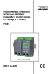
Fig. 1. View of the SM2 module
5
2. SET OF THE SM2 MODULE
The set consists of:
- SM2 module ............................................................................1 pc.
- user’s manual ..........................................................................1 pc.
- warranty card...........................................................................1 pc.
- plug with screw terminals ........................................................4 pcs
- hole plug of the RS-485 and RS-232 sockets .........................2 pc
- RS-232 cable to connect to the computer (1.5 m.)..................1 pc
When unpacking the module, please check whether the type and execution
code on the data plate correspond to the order.
3. BASIC REQUIREMENTS, SAFETY INFORMATION
Symbols located in this service manual mean:
WARNING!
Warning of potential, hazardous situations. Especially important.
One must acquaint with this before connecting the module.
The non-observance of notices marked by these symbols can occasion severe injuries of the personnel and the damage of the module.
CAUTION!
Designates a general useful note. If you observe it, handling of the
module is made easier. One must take note of this, when the module
is working inconsistently to the expectations. Possible consequences
if disregarded!
In the security scope the module meets the requirements of the EN 61010-1
standard.
Remarks concerning the operator safety:
1. General
l The SM2 module is destined to be installed in measuring systems.
l Non-authorized removal of the required housing, inappropriate use, incorrect
installation or operation create the risk of injury to personnel or damage to
equipment. For more detailed information please study the user’s manual.
6
l All operations concerning transport, installation, and commissioning as well as
maintenance must be carried out by qualified, skilled personnel and national
regulations for the prevention of accidents must be observed.
l According to this basic safety information, qualified, skilled personnel are
persons who are familiar with the installation, assembly, commissioning, and
operation of the product and who have qualifications necessary for their
occupation.
2. Transport, storage
Please observe the notes on transport, storage and appropriate handling.
Observe the climatic conditions given in Technical Data.
3. Installation
l The module must be installed according to the regulation and
instructions given in this user’s manual.
l Ensure proper handling and avoid mechanical stress.
l Do not bend any components and do not change any insulation distances.
l Do not touch any electronic components and contacts.
l Modules may contain electrostatically sensitive components, which can easily
be damaged by inappropriate handling.
l Do not damage or destroy any electrical components since this might
endanger your health!
4. Electrical connection
l Before switching the module on, one must check the correctness of
connection to the network.
l In case of the protection terminal connection with a separate lead one must
remember to connect it before the connection of the module to the mains.
l When working on live modules, the applicable national regulations for the
prevention of accidents must be observed.
l The electrical installation must be carried out according to the appropriate
regulations (cable cross-sections, fuses, PE connection). Additional
information can be obtained from the user’s manual.
l Apply a two-wire cable for the connection to the network acc. to the
EN 61010-1 standard.
l Do not connect the module to the network through an autotransformer.
l In the building installation, a cut-out or a circuit-breaker should exist, situated
near the device and easy accessible to the operator. It should be marked as
the element switching the device out.
7
l The documentation contains information about installation in compliance with
EMC (shielding, grounding, filters and cables). These notes must be observed
for all CE-marked products.
l The manufacturer of the measuring system or installed devices is responsible
for the compliance with the required limit values demanded by the EMC
legislation.
5. Operation
l Measuring systems including SM1 modules must be equipped with protection
devices according to the corresponding standard and regulations for
prevention of accidents.
l After the instrument has been disconnected from the supply voltage, live
components and power connections must not be touched immediately
because capacitors can be charged.
l The housing must be closed during operation.
l The RS-232 socket serves only to connect the device (Fig.5) working with the
MODBUS protocol. When the module is not used place the hole plug in the
RS-232 socket of the module.
6. Maintenance and servicing.
Please observe the manufacturer’s documentation.
Read all product-specific safety and application notes in this user’s manual.
l Before taking the module out, one must turn the supply off.
l The removal of the module housing during the warranty contract period may
cause its cancellation.
4. INSTALLATION
4.1 Way of fixing
The SM2 module is fixed on a 35 mm rail in accordance with EN 60715. The module
housing is made of a self-extinguishing plastic. Overall dimensions of the housing:
45 ´ 120 ´ 100 mm. One must connect to the module, external wires with crosssection up to 2.5 mm2
Overall dimensions and the fixing way are presented on the fig. 2.
8
Fig.2. Overall dimensions and way of fixing the module
4.2. External connection diagrams
Make the connection of input signals, supply
and interface acc. to the fig. 3, 4 and 5
Fig. 3
Connection way of external signals. The
connection diagram is also placed on the
module housing
9
The polarization is optional when supplying by d.c. voltage.
Measured signal
4 voltage inputs
4 current inputs
4 x 0/4... 20 mA
Connection way
4 x 0...10 V
Measured signal
2 voltage inputs + 2 current inputs
2 x 0/4... 20 mA
Connection way
2 x 0...10 V
4 resistance thermometer inputs
in 2-wire system or resistance
measurement
Fig. 4 connection way of input signals
Taking in consideration electromagnetic interference one must use shielded wires
to connect input signals and output signals. The supply must be connected by a
two-wire cable, with the appropriate wire diameter ensuring its protection by means
of a safety fuse.
10
Fig. 5 Connection way of RS-485 and RS-232
interfaces
11
5. HANDLING
After connecting external signals and switching the supply on, the SM2 module is
ready to work.
The lighted green diode signals the module work. The green diode (RxD) signals
the module polling, however the yellow diode (TxD) signals the module response.
Diodes should ignite in cycles during the data transmission, both through the
RS-232 and the RS-485 interface. One can program all module parameters by
means of RS-232 or RS-485.
The RS-232 port has constant transmission parameters in accordance with technical data, what enables the connection with the module even when programmed
parameters of the RS-485 digital output are unknown (address, mode, rate). The
RS-485 standard allows to the direct connection to 32 devices on a single serial
link up to 1200 m. To connect a greater number of devices, it is necessary to use
additional intermediate-separating systems.
The way of the interface connection is given in the user’s manual (fig.5). To obtain
the correct transmission, it is necessary to connect A and B lines in parallel with their
counterparts in other devices. The connection must be carried out with a screened
wire. The screen must be connect to the protective terminal in a single point. The
GND line serves to the additional protection of the interface line at long connections.
One must connect it to the protective terminal (it is not necessary for the correct
interface work). To obtain the connection with the PC computer through the RS-485
port, an RS-232/RS-485 converter (e.g. PD51 of Lumel’s production) or an RS-485
interface card is indispensable. The marking of transmission lines for the card in the
PC computer depends on the card manufacturer. To obtain the connection through
the RS-232 port, the wire added to the module is sufficient. The connection way of
both ports (RS-232 and RS-485) is shown on the fig. 5.
The module can be connected to the device of master type only through one interface port. In case of a simultaneous connection of both ports, the module will work
through the RS-232 interface.
5.1. Description of MODBUS protocol implementation
The transmission protocol describes ways of the information exchange between
devices through serial links.
The MODBUS protocol has been implemented in the module in accordance with the
PI-MBUS-300 Rev G specification of the Modicon company.
Set of parameters of the module serial link in the MODBUS protocol:
l Module address
- 1... 247
l Baud rate
- 2400, 4800, 9600, 19200, 38400, 57600,
115200 bit/s
l Working modes
- ASCII, RTU
12
l Information unit
l Maximal response time
- ASCII: 8N1, 7E1, 7O1
- RTU: 8N2, 8E1, 8O1, 8N1
- 300 ms.
The parameter configuration of the serial link is described in the further part of the
user’s manual. It consists on establishing the baud rate (Rate parameter), device
address (Adr parameter) and the information unit type (Mode parameter).
In case of the module connection with the computer through the RS-232 wire, the
module set automatically following transmission parameters:
Baud rate:
9600 bps,
Working mode:
RTU 8N1,
Address:
1.
Notice: Each module connected to the communication network must:
l have a unique address, different from addresses of other devices
connected to the network,
l identical baud rate and information unit type,
l the message sent with the address „0” is identified as the data
transmission mode (transmission to many devices)
Only one module can be connected to the master’s RS-232.
5.2. Description of the MODBUS protocol function
Following functions of the MODBUS protocol have been implemented in the
SM2 module
Opis funkcji
Code
Signification
03 (03 h)
06 (06 h)
16 (10 h)
17 (11 h)
Readout of n-register
Write of a single register
Write of n-registers
Slave device identification
Readout of n-registers (code 03h)
The function is not accessible in the broadcast mode.
Example: Readout of 2 registers beginning by the register with the 1DBDh
address (7613)
Demand:
Device
address
Function
01
03
Register address
Hi
1D
Lo
BD
Number of registers
Hi
00
Lo
02
Checksum
CRC
52 43
13
Answer:
Device
address
Function
Number
of bytes
01
03
08
Value from the register
1DBD (7613)
Value from the register
1DBE (7614)
3F
40
80
00
00
00
00
Checksum
CRC
42 8B
00
Write of values in the register (code 06h)
The function is accessible in the broadcast mode.
Example: Write the register with 1DBDh (7613) address
Demand:
Device
address
Function
01
06
Register address
Hi
1D
Lo
BD
Value for the register
1DBD (7613)
3F
80
00
Checksum
CRC
85 AD
00
Answer:
Device
address
Function
01
06
Register address
Hi
1D
Lo
BD
Value from the register
1DBD (7613)
3F
80
00
Checksum
CRC
85 AD
00
Device
address
Function
Write in n-registers (code 10h)
The function is accessible in broadcast mode.
Example: Write of two registers beginning from the register with 1DBDh (7613)
address
Demand:
01
10
Register Number of
address
registers Number Value for the register Value for the register
1DBD (7613)
1DBE (7614)
Hi Lo Hi Lo of bytes
3F 80 00 00 40 00 00 00
1D BD 00 02
08
Answer:
Device
address
Function
01
03
14
Register address
Hi
1D
Lo
BD
Number of registers
Hi
00
Lo
02
Checksum
CRC
52 43
Checksum
CRC
03 09
Report identifying the device (code 11h)
Demand:
Device
address
01
Checksum
(CRC)
Function
11
Answer:
Device
address
Function
Number
of bytes
Device
identifier
Device
state
Field depending on
the device type
X
11
08
89
FF
XXXXXX
Device address
- depends on the set value
Function
- function number: 0x11
Number of bytes
- 0x08
Device identifier
- 0x89
Device state
- 0xFF
Field depended of the
device
- XXXXXX
Output of OC type
- 0x01 - 2 outputs of OC type,
Type of input
Number of the
software version
Checksum
Checksum
01 X X X X X
- Field depended on the module execution code:
- 0x00 - four 0...10 V voltage inputs,
X 00 X X X X
- 0x01 - four 0/4...20 mA current inputs, X 01 X X X X
- 0x02 - two 0...10 V voltage inputs,
two 0/4...20 mA current inputs, X 02 X X X X
- 0x03 - four Pt100 inputs or four resistance
inputs up to 400 W,
X 03 X X X X
- software version implemented in the module
X X_ _ _ _4 - byte variable of float
- 2 bytes in case of work in RTU mode
- 1 byte in case of work in ASCII mode
Example:
Work in RTU mode, e.g. Mode = RTU 8N2 (value 0x02 in case of readout/write
through the interface
The device address is set on Adr=0x01
15
For the SM2 module the answer frame has the following shape:
Device
address
Function
Number
of bytes
Device
identifier
Device
state
Field depending on
the device type
Checksum
01
11
08
89
FF
01 01 3F 80 00 00
C3 60
It is the SM2 module:
- with two OC type outputs
- with four 0/4...20 mA current inputs
- software version: 1.00
5.3. Register map
Register map of SM2 series modules
Address
range
Value type
7000-7200
float (32 bit)
The value is placed in two successive 16-bit
registers. Registers contain the same data as
32-bit registers from the area 7500. The register
is for readout only
7200-7400
float (32 bit)
The value is placed in two successive 16-bit
registers. Registers contain the same data as
32-bit registers from the area
7600. Registers can be read out and written.
7500-7600
float (32 bit)
The value is placed in the 32-bit register.
The register is for readout only.
7600-7700
float (32 bit)
The value is placed in the 32-bit register.
Registers can be read out and written.
16
Description
The value is placed into 32bite registers.
7000
7500
Name
Identifier
Write (w)/Readout (r)
The value is located in two
successive 16-bite registers.
These registers include the
same data as 32-bite registers
from the area 7500.
5.4. Registers only for readout
r
Unit
-
Quantity name
Constant identifying the device
Value
0x89 - - h
0x - - 00h
0x - - 01h
0x - - 02h
SM2 identifier
Four 0...10 V voltage inputs
Four 0/4...20 mA currents
Two 0...10 V voltage input
Two 0/4...20 mA current input
0x - - 03h Four Pt100 inpus or
Four resistance inputs up to 400 W
7002
7501
Status 1
r
-
7004
7502
Status 2
r
-
7006
7008
7010
7012
7014
7016
7018
7020
7022
7024
7026
7028
7030
7032
7034
7503
7504
7505
7506
7507
7508
7509
7510
7511
7512
7513
7514
7515
7516
7517
W1
W2
W3
W4
WF
Min 1
Max 1
Min 2
Max 2
Min 3
Max 3
Min 4
Max 4
WF Min
WF Max
r
r
r
r
r
r
r
r
r
r
r
r
r
r
r
-
Status 1 is the register describing the present
module state
Status 2 is the register describing the present
module state
Measured value on the input 1
Measured value on the input 2
Measured value on the input 3
Measured value on the input 4
Calculated value basing on the function
Minimum of the measured value on the input 1
Maximum of the measured value on the input 1
Minimum of the measured value on the input 2
Maximum of the measured value on the input 2
Minimum of the measured value on the input 3
Maximum of the measured value on the input 3
Minimum of the measured value on the input 4
Maximum of the measured value on the input 4
Minimum of the calculated value
Maximum of the calculated value
17
Individual characteristic of the input 3
Individual characteristic of the input 2
Individual characteristic of the input 1
X
X
X
X
X
X
X
X
X
X
X
X
11
10
9
8
7
6
5
4
3
2
1
Signalling of the lower input 1 range
exceeding
Signalling of the upper input 1 range
exceeding
X
12
Signalling of the upper input 2 range
exceeding
X
13
Signalling of the lower input 3 range
exceeding
Signalling of the upper input 3 range
exceeding
Signalling of the lower input 2 range
exceeding
X
14
Signalling of the upper input 4 range
exceeding
X
bits 15
Signalling of the lower input 4 range
exceeding
Individual characteristic of the input 4
Description of the Status1 register
MSB
Bit-15...12 Empty
Bit value is always equal 0
Bit-11 Signalling of the lower range exceeding of input 4
0 - normal work
1 - range exceeding
Bit-10 Signalling of the upper range exceeding of input 4
0 - normal work
1 - range exceeding
Bit-9 Signalling of the lower range exceeding of input 3
0 - normal work
1 - range exceeding
Bit-8 Signalling of the upper range exceeding of input 3
0 - normal work
1 - range exceeding
Bit-7 Signalling of the lower range exceeding of input 2
0 - normal work
1 - range exceeding
Bit-6 Signalling of the upper range exceeding of input 2
0 - normal work
1 - range exceeding
18
0
LSB
Bit-5 Signalling of the lower range exceeding of input 1
0 - normal work
1 - range exceeding
Bit-4 Signalling of the upper range exceeding of input 1
0 - normal work
1 - range exceeding
Bit-3 Individual characteristic of the input 4
0 - individual characteristic switched on
1 - individual characteristic switched off
Bit-2 Individual characteristic of the input 3
0 - individual characteristic switched on
1 - individual characteristic switched off
Bit-1 Individual characteristic of the input 2
0 - individual characteristic switched on
1 - individual characteristic switched off
Bit-0 Individual characteristic of the input 1
0 - individual characteristic switched on
1 - individual characteristic switched off
Type of inputs
State of input 1
X
X
X
X
X
X
X
X
X
X
X
X
X
X
X
bits 15
14
13
12
11
10
9
8
7
6
5
4
3
2
1
MSB
Baud rate
Working mode and
information unit
State of input 2
State of input 3
State of input 4
Output 1 state of OC type
Output 2 state of OC type
Description of the Status 2 register
X
0
LSB
Bit-15 Empty
Bit value is always equal 0
Bit-14 Output 2 state of OC type
0 - OC switched off
1 - OC switched on
19
Bit-13 Output 1 state of OC type
0 - OC switched off
1 - OC switched on
Bit-12 State of measuring input 4
0 - input switched off (lack of measurement)
1 - input switched on
Bit-11 State of measuring input 3
0 - input switched off (lack of measurement)
1 - input switched on
Bit-10 State of measuring input 2
0 - input switched off (lack of measurement)
1 - input switched on
Bit-9 State of measuring input 1
0 - input switched off (lack of measurement)
1 - input switched on
Bit-8...6 Working mode and information unit
000 - interface switched off
001 - 8N1 - ASCII
010 - 7E1 - ASCII
011 - 7O1 - ASCII
100 - 8N2 - RTU
101 - 8E1 - RTU
110 - 8O1 - RTU
111 - 8N1 - RTU
Bit-5...3 Baud rate
000 - 2400 bit/s
001 - 4800 bit/s
010 - 9600 bit/s
011 - 19200 bit/s
100 - 38400 bit/s
101 - 57600 bit/s
110 - 115200 bit/s
Bit-2...0 Type of inputs
000 - 4 x 0...10 V
001 - 4 x 0/4...20 mA
010 - 2 x 0...10 V, 2 x 0/4...20 mA
011 - 4 x Pt100 resistance thermometer inputs or
4 x resistance inputs up to 400 W
20
5.5. Registers for readout and write
The value is placed in 32-bit
registers.
7200
7600
Symbol
Identifier
Write (w)/Readout (r)
The value is placed in two
successive 16-bytes registers. These registers include
the same data as 32-bit registers from the area 7600.
Table 1
r
Range
Description
-
Device identifier
Value
0x89 - - h SM2 Identifier
0x - - 00h Four 0...10 V voltage inputs
0x - - 01h Four 0/4...20 mA current inputs
0x - - 02h Two 0...10 V voltage input
Two 0/4...20 mA current input
0x - - 03h Four Pt100 inputs or
Four resistance inputs up to
400 W
7202
7601
Rate
W/r
0... 6
Baud rate of the RS-485 interface (bit/s)
Value
0
1
2
3
4
5
6
7204
7602
Mode
W/r
0... 7
2400
4800
9600
19 200
38400
57600
115200
Kind of transmission through the
RS-485 interface
Value
0
1
2
3
4
5
6
7
Interface switched off
ASCII 8N1
ASCII 7E1
ASCII 7O1
RTU 8N2
RTU 8E1
RTU 8O1
RTU 8N1
21
7206
7208
7603
7604
Adr
Apply
W/r
W/r
0... 247
Device address
0... 1
Acceptation of module transmission
parameter changes
Value
0
1
7210
7605
Input 1
W/r
0... 1
Lack of reaction
Acceptation of changes
Switching ON/OFF of the measuring
input 1
Value
0
1
Measuring input switched off
Measuring input switched on
In case of the input off the value 0
is returned
7212
7606
W1 type
W/r
Input 1 type
0... 1
Range
0
0... 1
0...10 V
for SM2-00XXX execution
0...10 V
for SM2-02XXX execution
0/4...20 mA
for SM2-01XXX execution
0 - Pt100
1 - Resistance < 400 W
Notice!
The range change of this parameter depends
on the execution code
7214
7607
Cnt W1
W/r
0... 6500
Measurement averaging time of the input 1
Value
0
0.1...6500
7216
7608
Ind W1
W/r
0... 1
The measurement is switched
off (module does not measure
on this input , the value 0
is returned)
Measuring time in seconds
Individual characteristic of the input 1
Value
22
0
off
1
on
7218
7609
X1 W1
W/r
-99999...99999
7220
7610
Y1 W1
W/r
-99999...99999
7222
7611
X2 W1
W/r
-99999...99999
7224
7612
Y2 W1
W/r
Parameters of the individual characteristic of input 1
On the base of given co-ordinates of two
points by the user the module determines
(from the system of equations) coefficients a
-99999...99999 and b of the individual characteristic.
Y1W1 = a .X1W1 + b
Y2W1 = a.X2W1 + b
ü
ý
þ
where:
X1 W1 and X2 W1 - measured value
Y1 W1 and Y2 W1 - Expected value on the
digital output.
The graphical presentation of the individual
characteristic is presented on the fig. 6.
At output signal recalculations, at first the module recalculates the value on the base of the
individual characteristic and then, this result is
transmitted to the arithmetic function,
7226
7613
Input 2
W/r
0... 1
Switching ON/OFF of the measuring
input 2
Value
0
Measuring input switched off
1
Measuring input switched on
In case of the input off the value 0
is returned
7228
7614
Typ W2
W/r
Input 2 type
0... 1
Range of changes as for the W1 type
7230
7615
Cnt W2
W/r
0... 6500
7232
7616
Ind W2
W/r
0... 1
Measurement averaging time of the input 2
Range of changes as for the Cnt W1 type
Individual characteristic of the input 2
Value
0
off
1
on
7234
7617
X1 W2
W/r
-99999...99999
Parameters of the individual characteristic of input 2
7236
7618
Y1 W2
W/r
-99999...99999
7238
7619
X2 W2
W/r
-99999...99999
The range changes as for: X1 W1, Y1 W1,
X2 W1, Y2 W1
7240
7620
Y2 W2
W/r
-99999...99999
23
7242
7621
Input 3
W/r
0... 1
Switching ON/OFF of the measuring
input 3
Value
0
Measuring input switched off
1
Measuring input switched on
In case of the input off the value 0
is returned
7244
7622
W3 type
W/r
Input 3 type
0... 1
Range
0
0... 1
0...10 V
for SM2-00XXX execution
0/4...20 mA
for SM2-01XXX execution,
for SM2-02XXX execution
0 - Pt100
1 - Resistance < 400 W
Notice!
The range change of this parameter depends
on the execution code
7246
7623
Cnt W3
W/r
0... 6500
7248
7624
Ind W3
W/r
0... 1
Measurement averaging time of the input 3
Range of changes as for the Cnt W1 type
Individual characteristic of the input 3
Value
0
off
1
on
7250
7625
X1 W3
W/r
-99999...99999
Parameters of the individual characteristic of input 3
7252
7626
Y1 W3
W/r
-99999...99999
7254
7627
X2 W3
W/r
-99999...99999
The range changes as for: X1 W1, Y1 W1,
X2 W1, Y2 W1
7256
7628
Y2 W3
W/r
-99999...99999
7258
7629
Input 4
W/r
0... 1
Switching ON/OFF of the measuring
input 4
Value
0
Measuring input switched off
1
Measuring input switched on
In case of the input off the value 0
is returned
24
7260
7630
W4 type
W/r
Input 4 type
0... 1
Range of changes as for W1 type
7262
7631
Cnt W4
W/r
0... 6500
Czas uœredniania pomiaru wejœcia 4
Zakres zmian jak dla Cnt W1
7264
7632
Ind W4
W/r
0... 1
Individual characteristic of the input 4
Value
0
off
1
on
7266
7633
X1 W4
W/r
-99999...99999
Parameters of the individual characteristic of input 4
7268
7634
Y1 W4
W/r
-99999...99999
7270
7635
X2 W4
W/r
-99999...99999
The range changes as for: X1 W1, Y1 W1,
X2 W1, Y2 W1
7272
7636
Y2 W4
W/r
-99999...99999
7274
7637
A
W/r
0... 12
7276
7278
7280
7638
7639
7640
B
C
D
W/r
W/r
W/r
0... 12
0... 12
0... 12
Parameters of the mathematical function
Value
0
Parameter switched off
1
Result 1 (input 1) (W1)
2
Result 2 (input 2) (W2)
3
Result 3 (input 3) (W3)
4
Result 4 (input 4) (W4)
5
Root of the result 1 Ö W1
6
Root of the result 2 Ö W2
7
Root of the result 3 Ö W3
8
9
10
11
12
Root of the result 4 Ö W4
Result 1 squared (W12)
Result 2 squared (W22)
Result 3 squared (W32)
Result 4 squared (W42)
Parameters of the mathematical function
serves to recalculate the measured input
quantity into th output quantity (WF) basing
on the function: WF=A<Operator1>B<Operator2>C<Operator3>D
When recalculating the input signal.the
module recalculates at first the value
basing on the individual characteristic
and then, this result is transmitted to the
arythmetical function. Examples of using
mathematical functions are presented
in the section „Examples of module
programming”.
25
7282
7284
7641
7642
Operator1
Operator2
W/r
W/r
0... 3
0... 3
7286
7643
Operator3
W/r
0... 3
Operators of the mathematical function
Value
0
1
2
3
Addition „+”
Subtraction „-”
Multiplication „*”
Division „/”
The calculation of the output value is carried
out basing on the assumpted operator
weight i.e.: At first multiplication and division
operations are realised and after addition and
subtraction operations. „*” and „/” operators
and „+” and „-” operators have the same
importance weight. Examples of using mathematical functions are presented in the section
„Examples of module programming”.
7288
7644
WF
Operator
W/r
0... 3
Mathematical operations on the result
of WF function
Value
0
1
2
3
Operator switched off
Extraction of roots ÖWF
Squaring WF2
Inverse
1/WF
The module at first calculates the function programmed by the user and then, its result can
be submitted to further operations described
in this point. In the case of the WF operator
switching on the final result is situated in the
WF register, however the result from before
this operation is not accessible.
7290
7645
OC1
W/r
0... 4
Input quantity, on which the output 1 of
OC type has to operate.
Value
0
1
2
3
4
Input 1 (W1)
Input 2 (W2)
Input 3 (W3)
Input 4 (W4)
Result of the function (WF)
Recalculated results, basing on the individual
user’s characteristic (if it is switched on)
and basing on programmed mathematical
function (if the value 4 has been selected and
the function is switched on) are transmitted to
the output. In case of choosing the value 4 and
switching the mathematical function off, the
value 0 is transmitted to the output.
26
7292
7646
OC1 type
W/r
0... 4
Output 1 type of OC type
Value
0
1
2
3
4
Normal
Schwitched on
Schwitched off
Manually schwitched on
Manually schwitched off
The graphical imaging of the OC type output operation is presented on the fig. 7.
7294
7647
Prl OC1
W/r
-99999...99999 Lower threshold of output 1 OC type operation
7296
7648
Prh OC1
W/r
-99999...99999 Upper threshold of output 1 OC type operation
7298
7649
Dly OC1
W/r
0... 6500
7300
7650
OC2
W/r
0... 4
The operation delay of the output 1 of OC
type in seconds.
The OC output will be steered up if the
alarm active state will be longer than the
programmed value.
The input quantity on which the output
2 of OC type is to operate.
Value
0
1
2
3
4
Result 1 (W1)
Result 2 (W2)
Result 3 (W3)
Result 4 (W4)
Result of (WF) function
Recalculated results, basing on the
individual user’s characteristic (if it is
switched on) and basing on programmed
mathematical function (if the value 4 has
been selected and the function is switched
on) are transmitted to the output. In case
of choosing the value 4 and switching the
mathematical function off, the value 0 is
transmitted to the output.
7302
7651
OC2 type
W/r
0... 4
Output 2 type of OC type
Value
0
1
2
3
4
Normal
Schwitched on
Schwitched off
Manually schwitched on
Manually schwitched off
The graphical imaging of the OC type output operation is presented on the fig. 7.
27
7304
7652
Prl OC2
W/r
-99999...99999 Lower threshold of output 2 OC type operation
7306
7653
Prh OC2
W/r
-99999...99999 Upper threshold of output 2 OC type operation
7308
7654
Dly OC2
W/r
0... 6500
7310
7655
Del min 1
W/r
0... 1
Erasing of the input 1 minimal value
7312
7656
Del max 1
W/r
0... 1
Erasing of the input 1 maximal value
7314
7657
Del min 2
W/r
0... 1
Erasing of the input 2 minimal value
7316
7658
Del max 2
W/r
0... 1
Erasing of the input 2 maximal value
7318
7659
Del min 3
W/r
0... 1
Erasing of the input 3 minimal value
7320
7660
Del max 3
W/r
0... 1
Erasing of the input 2 maximal value
7322
7661
Del min 4
W/r
0... 1
Erasing of the input 4 minimal value
7324
7662
Del max 4
W/r
0... 1
Erasing of the input 2 maximal value
7326
7663
Del min WF W/r
0... 1
Erasing of the function result
minimal value
7328
7664 Del max WF W/r
0... 1
Erasing of the function result
maximal value
7330
7665
Del min
max
0... 1
Erasing of minimal and maximal value
W/r
The operation delay of the output 2 of OC
type in seconds.
The OC output will be steered up if the
alarm active state will be longer than the
programmed value.
Range
0
1
lack of operation
erasing
Caution!
After carrying out the erasing operation the
value of this register is zero.
7332
7666
Comp W1
W/r
0... 40
7334
7667
Comp W2
W/r
0... 40
28
Resistance value of wires connecting the
sensor with the module input 1
The register is used only in the execution
for the resistance or temperature measurement
Resistance value of wires connecting the
sensor with the module input 2
The register is used only in the execution
for the resistance or temperature measurement
7336
7668
Comp W3
W/r
0... 40
7338
7669
Comp W4
W/r
0... 40
7340
7670
W/r
0... 1
Standard
Resistance value of wires connecting the
sensor with the module input 1
The register is used only in the execution
for the resistance or temperature measurement
Resistance value of wires connecting the
sensor with the module input 1
The register is used only in the execution
for the resistance or temperature measurement
Restoration of manufacturer’s parameters
Value
0
1
lack of operation
Write of manufacturer’ s
parameters
Introduction of the value 1 will cause the
write of manufacturer’s parameters into
the module acc. to the table. 2
* i = 1... 4
X1 Wi value in the module input of systems => Y1 W1 digital value
X2 Wi value in the module input of systems => Y2 W1 digital value
Other points of the characteristic are calculated
Fig. 6. Individual user’s characteristic
29
a) nor (PrH OC > PrL OC)
b) nor (PrH OC < PrL OC)
c) OFF
d) On
Fig. 7. Types of OC1 and OC2 output
30
Caution!
- In the execution for the measurement of resistance or temperature (Pt100) only
the two-wire method is accessible. The resistance of the wire connecting the sensor with the module must be introduced from the master device (e.g. PC). For this
purpose we propose:
- switch the module into the resistance measurement mode,
- short-circuit the ends of wires which the sensor is fixed to,
- read out the numeric value which represents the resistance of both wires,
- introduce the read out value into the Comp WX (X = 1... 2) register of the
appropriate input.
Each input has a separate compensation register. The described procedure must
be carried out for switched on measuring inputs. The resistance can be also measured by any meter (class < 0.1%) and introduced into registers.
- In case on user’s individual characteristic switched on, the measured result is
linearly transformed in accordance with introduced X and Y parameters. Then,
the calculated value is found in the result register.
- In case of mathematical operations switching on, the result in the WF register is
calculated in accordance with the equation introduced to the module. Sequence
of calculations: result recalculation basing on the user’s individual characteristic
(if it is switched on), calculation of the introduced function, carrying out the operation on the function result.
- The module supervises currently the value of the introduced parameter . In case
when the introduced value is beyond the range of changes given in the table 1,
the module does not make the parameter write.
31
Manufacturer’ parameters of the SM2 module
32
Table 2
Symbol
Manufacturer’s value
Input 1,2,3,4
1 (switched on)
Cnt W1, Cnt W2, Cnt W3, Cnt W4
1 (1 s)
Ind W1, Ind W2, Ind W3, Ind W4
0 (switched off)
X1 W1, X1 W2, X1 W3, X1 W4
0
Y1 W1, Y1 W2, Y1 W3, Y1 W4
0
X2 W1, X2 W2, X2 W3, X2 W4
0
Y2 W1, Y2 W2, Y2 W3, Y2 W4
0
A,B,C,D
0 (switched off)
Operator 1,2,3
0 („+”)
Operator WF
0 (switched off)
Rate
2 (9600)
Mode
4 (RTU 8N2)
Address
1
OC1
0 (input 1)
Typ OC1
4 (switched off manually)
Prl OC1
0
Prh OC1
0
Dly OC1
0 (lack of delay)
OC2
0 (Input 1)
Typ OC2
4 (switched off manually)
Prl OC2
0
Prh OC2
0
Dly OC2
0 (lack of delay)
Comp W1, Comp W2, Comp W3, Comp W4
0
6. TECHNICAL DATA
INPUTS:
Depending on the execution code for individual channels:
- voltage measurement
0...10 V
input resistance > 1 MW
- current measurement
0...20 mA input resistance < 10 W
- resistance measurement 0... 400 W
- Pt100
(- 200... + 850)°C
Current flowing through the Pt 100 sensor:
Resistance of leads connecting the
resistance thermometer with the module:
Pt100 characteristic
< 250 mA
max 20 W/wire
acc. to EN 60751+A2
OUTPUTS:
- open collector (OC)
voltageless of OC type with npn transistor
(maximal load 25 mA)
range of added voltages: 5... 24 V d.c.
- digital
a) RS-485 interface
transmission protocol
ASCII
RTU
baud rate
address
MODBUS
8N1, 7E1, 7O1
8N2, 8E1, 8O1, 8N1
2400, 4800, 9600, 19200, 38400, 57600
115200 bauds
1... 247
b) RS-232 interface
transmission protocol
MODBUS
RTU
8N1
baud rate
9600 bauds
address
1
maximal response time to the query frame: 300 ms.
Basic error
0.1% of measuring range
Additional error from ambient
temperature changes
± (0.1% of range/10K)
Measurement time of a single
input:
min 100 ms (programmable)
the sampling frequency of the input
is 1 kHz (averaged measurement)
33
Rated operation conditions:
- supply voltage depending on the
execution code
- supply voltage frequency
- ambient temperature
- storage temperature
- relative humidity
- preheating time
85... 253 V a.c./d.c.
20... 50 V a.c./d.c.
40... 440 Hz
-10...23...55°C
-25...+85°C
< 95% (condensation inadmissible)
10 min
Sustained overload:
- resistance thermometers
- measurement of voltage, current
and resistance
10%
Short-duration overload (3 s):
- voltage input
- current input
10 Un
10 In
1%
Ensured protection grade acc. to EN 60529:
- through the housing
IP 40
- electrical connections
IP 20
Dimensions
45 ´ 120 ´ 100 mm
Weight
< 0.3 kg
Fixing
on a 35 mm rail
Power consumption
< 4 VA
Resistance against decays
acc. to EN 50082-2
Electromagnetic compatibility:
- immunity
- emission
- additional error from electromagnetic hazard
acc. to EN 50082-2
acc. to EN 50081-2
< 0.2%
Safety requirements acc. to EN 61010-1 standard:
- installation category
III
- pollution grade
2
- phase-to-earth working voltage:
- supply
300 V
- input
50 V
- output
50 V
34
7. BEFORE A FAILURE WILL BE DECLARED
In case of incorrect symptoms please to acquaint with the table below.
SYMPTOMS
PROCEDURE
1. The module diode is
not illuminated.
Check the connection of the network cable
2. The module does not
communicate with
the device master via
the RS-232 port.
Lack of transmission
signalling on RxD
and TxD diodes.
Check if the wire is connected to the appropriate
module socket.
Check if the device master is set on 9600 baud
rate, 8N1 mode and address 1.
3. The module does not
communicate with
the device master
via the RS-485 port.
Lack of transmission
signalling on RxD
and TxD diodes.
Check if the wire is connected to the appropriate module terminal. Check if the device master is set on the
same transmission parameters as the module (baud
rate, mode, address). In case of necessity to change
transmission parameters when we cannot communicate through RS-485 one can use the RS-232 port
which has constant transmission parameters (in
case of further problems, see the section 2). After
changing e RS-485 parameters into the required
one, one can switch over on RS-485 port.
4. The module returns
the value 0 on the
given input.
Check if the input which the value 0 is returned
on, is not switched out and if the averaging time is
> 0.1 s. Check if the user’s individual characteristic
with zero parameters is not switched on.
5. The result in WF register (function result)
is inconsistent with
our expectations,
Check the correctness of the introduced formula.
Check if the operation sequence is correct. The
operator weight is essential - at first, multiplication
and division are carried out and next, addition
and subtraction. Perhaps it is sufficient to reorder
results in the formula. See programming examples
in the section 8
Check the correctness of the input signal connection. The IE20 value is set when the measured signal is beyond the measuring range. The recorded
IE20 value in max and min registers remains till
the time of its erasing by the user.
6. In result registers the
IE20 value is min or
max (e.g. in Lumel
Energy „***” )
7. The value of the
measured resistance or temperature is
overstated.
Check if correct values of the wires’ resistance have
been introduced to Comp W1, Comp W2, Comp W3
and Comp W4 registers. In case of necessity, one
must introduce this value. See the user’s manual
under the description of the Status 2.
REMARKS
(RS-232 has
constant transmission parameters)
Concerns only
the module
for resistance
measurement
or for co-operation with a
Pt100 sensor.
35
8. EXAMPLES OF SM2 MODULE PROGRAMMING
Example 1: Switching appropriate measuring inputs and averaging time
on
Module operation with two inputs ( e.g. 1 and 3). The first input has to average with
a 100 ms time (0.1s) and the third input with a 10 min time (600 s)
One must program the parameter:
l Input 1 = 1
l Input 2 = 0
l Input 3 = 1
l Input 4 = 0
l Cnt W1 = 0.1
l Cnt W3 = 600
The module will carry out the measurement on the input 1 and 3.
In the register corresponding to first input, the result will be refreshed every 100 ms
and in the register corresponding to third register, every 10 minutes.
Example 2: Programming the user’s individual characteristic
One must program the module in such a way that it measures the water level in
a tank with characteristic: 4 mA => 0 m., 20 mA => 3.6 m. in the input 1, whereas
on the input 2, the temperature with characteristic: 4 mA => 0°C, 20 mA => 50 °C
One must program the parameter:
l Ind W1 = 1
l X1 W1 = 0
l Y1 W1 = 0
l X2 W1 = 3.6
l Ind W2 = 1
l X1 W2 = 4
l Y1 W2 = 0
l X2 W2 = 20
l Y2 W2 = 50
Example 3: Programming mathematical function
One must program the module in such a way that it measures the current on the
input 1, the voltage on the input 2, and calculate the apparent power of the variable
signal. The module is working with transducers of variable signal into a standard
signal, e.g. P11Z transducer. The measurement of max current = 1200 A (0 =®
4 mA; 1200 A =® 20 mA), measurement of max voltage = 400 V ( 0 V =® 0 V;
400 V =® 10 V).
36
One must program the parameter:
l Ind W1 = 1
l X1 W1 = 4
l Y1 W1 = 0
l X2 W1 = 20
l Y2 W1 = 1200
l Ind W2 = 1
l X1 W2 = 0
l Y1 W2 = 0
l X2 W2 = 10
l Y2 W2 = 400
one must carry out the following equation: S = U . I
l A = 1 (result from input 1)
l B = 2 (result from input 2)
l Operator 1 = 2 (multiplication).
The apparent power 0...480 000 VA will be calculated in the WF register, whereas
the 0...1200 A current in the result register 1, and the 0...400 V voltage in the result
register 2.
Example 4: Programming mathematical function
The module is working with:
On the input 1 -> a.c. current transducer on standard signal, e.g. P11Z.
Current measurement on the 5 A range (transducer characteristic -> 0 A => 4 mA,
5 A => 20 mA).
On the input 2 -> a.c. voltage transducer on standard signal, e.g. P11Z.
Voltage measurement on the 400 V range (transducer characteristic -> 0 V => 0
V
400 V => 10 V)
On the input 3 -> active on standard signal, e.g. P34P or PP84
Active power measurement on the 2000 W range (transducer characteristic 0
W => 4 mA 2000 W => 20 mA.
Its task is to transmit voltage, current and reactive power values to the system.
One must program the parameter:
l Ind W1 = 1
l X1 W1 = 4
l Y1 W1 = 0
l X2 W1 = 20
l Y2 W1 = 5
37
Ind W2 = 1
X1 W2 = 0
Y1 W2 = 0
X2 W2 = 10
Y2 W2 = 400
Ind W3 = 1
X1 W3 = 4
Y1 W3 = 0
X2 W3 = 20
Y2 W3 = 2000
One must carry out the following formula:
l
l
l
l
l
l
l
l
l
l
And program as follows:
l A = 10 (squared result from the output 2)
l B = 9 (squared result from the output 1)
l C = 11 (squared result from the output 3)
l Operator 1 = 2 (multiplication)
l Operator 2 = 1 (subtraction)
l Operator WF = 1 (extraction of roots from the function result)
) will be calculated in the WF register,
The reactive power 0...2000 var (
whereas the current 0...5 A in the result 1 register, the voltage 0...400 V in the result
2 register and the active power 0...2000 W in the result 3 register.
Example 5 : Programming mathematical function
The example is based on the example 4, but instead the calculation of the reactive
power, one must calculate cosj.
l We program individual characteristic parameters acc to the example 4,
however the function must be programmed acc. to the formula:
cosj
We must program:
l A = 3 (result from the input 3, power)
l B = 2 (result from the input 2, voltage)
l C = 1 (result from the input 3, current)
l Operator1 = 3 (division)
l Operator2 = 3 (division)
We have to pay attention to the weight of mathematical operations. At first, the
38
multiplication and division are carried out, and next, the subtraction and addition.
Since the weight of multiplication and division are the same, the first operation in
the formula is carried out.
For this reason, the given formula above must be written as:
cosj = P/U/I and not as P/U *I.
In the WF register, the phase displacement angle will be calculated:
( cosj
),
However, the current 0...5 A in the result 1 register, the voltage 0...400 V in the result
2 register and the active power 0...2000 W in the result 3 register.
Example 6 : Programming the OC type input
One must program the module such a way that the OC1 output could react on the
input 1 and the OC2 output on the input 4. The signal on the input 4 is recounted
into temperature (4 mA = 0°C ; 20 mA = 100 °C ) The OC1 output is to be actice
in the interval 2...4 V, and the OC2 output is to be active after exceeding 50°C and
be desactivated below 20°C.
One must program the parameter:
l Ind W4 = 1
l X1 W4 = 4
l Y1 W4 = 0
l X2 W4 = 20
l Y2 W4 = 100
l OC1 = 0
l Typ OC1 = 1
l Prl OC1 = 2
l Prh OC1 = 4
l OC2 = 3
l Typ OC2 = 0
l Prl OC1 = 20
l Prh OC1 = 50
The OC1 output will operate acc. to the fig. 7a and the OC2 output acc. to the fig.
7d.
39
9. ORDERING CODES
SM2 Module
XX
X
Input signal*:
4 voltage inputs
0...10 V .....................................00
4 current inputs
0/4...20 mA................................01
2 voltage input + 2 current input
0...10V + 0/4...20 mA ................02
4 resistance or Pt100 inputs
Pt100 or resistance < 400 W ....03
on order** ....................................... ................................................. XX
Supply:
85... 253 V a.c./d.c..................................................................................... 1
20... 50 V a.c./d.c....................................................................................... 2
on order ** ................................................................................................. X
Acceptance tests:
without a quality inspection certificate ............................................................8
with a quality inspection certificate .................................................................7
acc. customer’s agreement** ........................................................................ X
*
Possible version of a cheaper module with a smaller quantity of inputs.
Possibility to mix input kinds (e.g. 1 voltage and 3 current inputs).
** Code numbers must be agreed with the manufacturer.
EXAMPLE OF ORDER
When ordering, please respect successive code numbers.
Code: SM2 01 1 0 means:
SM2
- 2-channel module of analog inputs,
01 - module with 4 current inputs 0/4...20 mA,
1 - supply voltage: 85... 253 V a.c./d.c.
8 - without a quality inspection certificate.
40
X
10. MAINTENANCE AND WARRANTY
The SM2 module does not require any periodical maintenance.
In case of some incorrect operations:
1. After the dispatch date and within the period stated in the warranty card
One should return the instrument to the Manufacturer’s Quality Inspection Dept.
If the module has been used in compliance with the instructions, we warrants to
repair it free of charge. The disassembling of the housing causes the cancellation
of the granted warranty.
2. After the warranty period:
One should send the instrument to repair it in an authorized service workshop.
Spare parts are available for the period of five years from the date of purchase.
Our policy is one of continuous improvement and we reserve the
right to make changes in design and specifications of any products
as engineering advances or necessity requires and revise the above
41
42
43
SM2-07.B