1
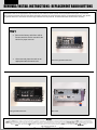
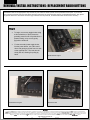
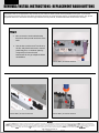
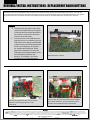
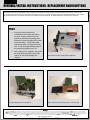
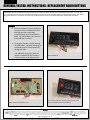
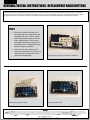
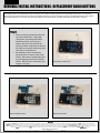
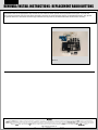
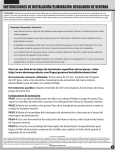
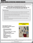
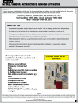
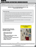
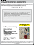
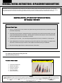
REMOVAL/INSTALL INSTRUCTIONS: REPLACEMENT RADIO BUTTONS ATTENTION: Refer to the appropriate shop manual for your vehicle to obtain specific service procedures for this part. If you do not have a service manual or have any reservations with this instruction set, please seek the services of a qualified technician. Also, please pay special attention to all cautions and warnings included in the shop manual, and Read and follow all instructions carefully! REMOVAL/INSTALL OF RADIO BUTTONS (Part# 76821) GM Vehicles 1995-2005 General Tech Tips: Work in a location that is clean & static-free (static discharge has the potential to permanently damage electrical components). Use plastic zip-lock bags or compartment trays to temporarily store small screws and other items that may need disassembly from the radio. Labeling these containers with respect to their subassemblies will make organization and re-assembly a lot easier. A plastic pry tool is useful. It will not easily damage delicate trim like a screwdriver or metal pry bar Upon disassembly of the button components, pay specific attention to the ‘layering’ of components as this will be critical to the proper function of the replacement buttons during re-installation Be aware of sharp edges from the metal enclosures of the radios For a digital copy of this instruction sheet, please visit:: http://www.dormanproducts.com Please Wear Protective Eyewear! Common Tools Used: Flat-head screwdrivers Needle-nose pliers 3/16 Hex nut driver 1/8 Hex nut driver Torx 15 bit driver Socket wrench set Even though attempt is made to ensure this information is complete and accurate, it is impossible to account for all possible circumstances or situations. consult with a qualified auto before attempting to perform any work you are not qualified to do. Automobiles can be hazardous to work on; be sure to take all precautions. Failure to do so may result in property damage or personal injury. Certain motor standards and performance requirements may apply to your motor (such as Federal Motor Standards by the National Highway Safety Administration). sure that your work is performed in accordance with such standards and that you do not disable any motor feature. No ©2011 Dorman Products, Inc. in or in part approval. REMOVAL/INSTALL INSTRUCTIONS: REPLACEMENT RADIO BUTTONS ATTENTION: Refer to the appropriate shop manual for your vehicle to obtain specific service procedures for this part. If you do not have a service manual or have any reservations with this instruction set, please seek the services of a qualified technician. Also, please pay special attention to all cautions and warnings included in the shop manual, and Read and follow all instructions carefully! Step 1: Remove the factory radio from vehicle. Please consult a service manual for the vehicle for proper removal. Once removed, place the radio on an appropriate static-free work area. CD-Type Radio Head Unit Cassette-Type Radio Head Unit Rear View Even though attempt is made to ensure this information is complete and accurate, it is impossible to account for all possible circumstances or situations. consult with a qualified auto before attempting to perform any work you are not qualified to do. Automobiles can be hazardous to work on; be sure to take all precautions. Failure to do so may result in property damage or personal injury. Certain motor standards and performance requirements may apply to your motor (such as Federal Motor Standards by the National Highway Safety Administration). sure that your work is performed in accordance with such standards and that you do not disable any motor feature. No ©2011 Dorman Products, Inc. in or in part approval. REMOVAL/INSTALL INSTRUCTIONS: REPLACEMENT RADIO BUTTONS ATTENTION: Refer to the appropriate shop manual for your vehicle to obtain specific service procedures for this part. If you do not have a service manual or have any reservations with this instruction set, please seek the services of a qualified technician. Also, please pay special attention to all cautions and warnings included in the shop manual, and Read and follow all instructions carefully! Step 2: To begin, remove any toggle knobs using a thin screwdriver or pliers; these are generally press-fit onto a keyed shaft or a plastic housing, so be sure to gently pry/pull the knobs off! For the secondary lower toggle knobs, like the power button, use a thin screw driver and gently pry a little from one side to the opposite side. The knob should slowly inch off, allowing for pulling by hand. Knob Removal Type 2 Knob Removal Type 1 Without Knobs Even though attempt is made to ensure this information is complete and accurate, it is impossible to account for all possible circumstances or situations. consult with a qualified auto before attempting to perform any work you are not qualified to do. Automobiles can be hazardous to work on; be sure to take all precautions. Failure to do so may result in property damage or personal injury. Certain motor standards and performance requirements may apply to your motor (such as Federal Motor Standards by the National Highway Safety Administration). sure that your work is performed in accordance with such standards and that you do not disable any motor feature. No ©2011 Dorman Products, Inc. in or in part approval. REMOVAL/INSTALL INSTRUCTIONS: REPLACEMENT RADIO BUTTONS ATTENTION: Refer to the appropriate shop manual for your vehicle to obtain specific service procedures for this part. If you do not have a service manual or have any reservations with this instruction set, please seek the services of a qualified technician. Also, please pay special attention to all cautions and warnings included in the shop manual, and Read and follow all instructions carefully! Step 3: Next, remove the various bolts/screws that secure the top metal enclosure of the radio. Use the hex nut driver and Torx driver to do this, and place these items in a small plastic bag, box, or container (label by component) to ensure that the bolts/screws do not get misplaced before reinstallation. Various Bolts / Screws for Removal Various Bolts / Screws for Removal Various Bolts / Screws for Removal Even though attempt is made to ensure this information is complete and accurate, it is impossible to account for all possible circumstances or situations. consult with a qualified auto before attempting to perform any work you are not qualified to do. Automobiles can be hazardous to work on; be sure to take all precautions. Failure to do so may result in property damage or personal injury. Certain motor standards and performance requirements may apply to your motor (such as Federal Motor Standards by the National Highway Safety Administration). sure that your work is performed in accordance with such standards and that you do not disable any motor feature. No ©2011 Dorman Products, Inc. in or in part approval. REMOVAL/INSTALL INSTRUCTIONS: REPLACEMENT RADIO BUTTONS ATTENTION: Refer to the appropriate shop manual for your vehicle to obtain specific service procedures for this part. If you do not have a service manual or have any reservations with this instruction set, please seek the services of a qualified technician. Also, please pay special attention to all cautions and warnings included in the shop manual, and Read and follow all instructions carefully! Step 4: Carefully lift the top portion of the metal enclosure and place aside; the top green PCB board also has screws that need to be removed to access wire connectors that mate to the radio face. Once the screws on the PCB board are removed (secure in a container!), the top PCB board can be slightly moved/rotated to allow access to the wiring harness that needs to be unfastened. Be careful to not yank/pull the PCB Board! Gently disconnect the harness from the lower PCB board and the side hardness on the top PCB board (underneath; see pictures). If necessary, use a small screwdriver for controlled assistance. Gently placing top board aside; still connected! Notice the three wiring plugs that can be unfastened. Mini hex bolts for removal There are two wire harnesses that mate the faceplate to the lower PCB board. And the third harness that attaches the top PCB board to the lower board. Even though attempt is made to ensure this information is complete and accurate, it is impossible to account for all possible circumstances or situations. consult with a qualified auto before attempting to perform any work you are not qualified to do. Automobiles can be hazardous to work on; be sure to take all precautions. Failure to do so may result in property damage or personal injury. Certain motor standards and performance requirements may apply to your motor (such as Federal Motor Standards by the National Highway Safety Administration). sure that your work is performed in accordance with such standards and that you do not disable any motor feature. No ©2011 Dorman Products, Inc. in or in part approval. REMOVAL/INSTALL INSTRUCTIONS: REPLACEMENT RADIO BUTTONS ATTENTION: Refer to the appropriate shop manual for your vehicle to obtain specific service procedures for this part. If you do not have a service manual or have any reservations with this instruction set, please seek the services of a qualified technician. Also, please pay special attention to all cautions and warnings included in the shop manual, and Read and follow all instructions carefully! Step 5: Once these wire harnesses are unfastened, the front face plate can be removed. Start by taking two narrow flathead screwdrivers and placing them between the plastic faceplate locking tabs and metal casing. This should provide enough clearance to unclasp the locking tabs. Do this throughout the perimeter of the faceplate and gently slide it off. When sliding out the faceplate, watch that the loose wiring harnesses on the other side do not get tangled/caught onto anything. Slowly sliding off the front faceplate Screwdrivers used to wedge plastic clasps out. Fully removed you will see this, but it’s not over yet. Even though attempt is made to ensure this information is complete and accurate, it is impossible to account for all possible circumstances or situations. consult with a qualified auto before attempting to perform any work you are not qualified to do. Automobiles can be hazardous to work on; be sure to take all precautions. Failure to do so may result in property damage or personal injury. Certain motor standards and performance requirements may apply to your motor (such as Federal Motor Standards by the National Highway Safety Administration). sure that your work is performed in accordance with such standards and that you do not disable any motor feature. No ©2011 Dorman Products, Inc. in or in part approval. REMOVAL/INSTALL INSTRUCTIONS: REPLACEMENT RADIO BUTTONS ATTENTION: Refer to the appropriate shop manual for your vehicle to obtain specific service procedures for this part. If you do not have a service manual or have any reservations with this instruction set, please seek the services of a qualified technician. Also, please pay special attention to all cautions and warnings included in the shop manual, and Read and follow all instructions carefully! Step 6: Once the faceplate is moved, isolate this component to the immediate work area and keep the other components organized neatly (loose screws/bolts in bags). Flip the faceplate over; there will be several bolts to remove. Once again, please be careful handling the PCB boards. Any static discharge or accidental puncture could permanently damage the radio. The PWR/VOL Knob keyed-shaft will need to be unbolted to fully detach the PCB board from the faceplate as well. The faceplate off Use a metric socket or wrench to remove this nut to free the faceplate from the PCB Board. Bolts to remove as shown in red Even though attempt is made to ensure this information is complete and accurate, it is impossible to account for all possible circumstances or situations. consult with a qualified auto before attempting to perform any work you are not qualified to do. Automobiles can be hazardous to work on; be sure to take all precautions. Failure to do so may result in property damage or personal injury. Certain motor standards and performance requirements may apply to your motor (such as Federal Motor Standards by the National Highway Safety Administration). sure that your work is performed in accordance with such standards and that you do not disable any motor feature. No ©2011 Dorman Products, Inc. in or in part approval. REMOVAL/INSTALL INSTRUCTIONS: REPLACEMENT RADIO BUTTONS ATTENTION: Refer to the appropriate shop manual for your vehicle to obtain specific service procedures for this part. If you do not have a service manual or have any reservations with this instruction set, please seek the services of a qualified technician. Also, please pay special attention to all cautions and warnings included in the shop manual, and Read and follow all instructions carefully! Step 7: Secure the faceplate PCB board and have the plastic-only components in the immediate work area. There is a white plastic back-plate that helps secure the button subassemblies. Note that this back-plate has tabs that clasp onto the front plastic cover. Unclasp these areas using a small/thin screwdriver. Once removed, take caution with the remaining components—as they are now unsecured and may easily come loose (rather small components). Plastic backing plate removed Unclasp plastic tabs using a small thin screwdriver Remaining subassembly Even though attempt is made to ensure this information is complete and accurate, it is impossible to account for all possible circumstances or situations. consult with a qualified auto before attempting to perform any work you are not qualified to do. Automobiles can be hazardous to work on; be sure to take all precautions. Failure to do so may result in property damage or personal injury. Certain motor standards and performance requirements may apply to your motor (such as Federal Motor Standards by the National Highway Safety Administration). sure that your work is performed in accordance with such standards and that you do not disable any motor feature. No ©2011 Dorman Products, Inc. in or in part approval. REMOVAL/INSTALL INSTRUCTIONS: REPLACEMENT RADIO BUTTONS ATTENTION: Refer to the appropriate shop manual for your vehicle to obtain specific service procedures for this part. If you do not have a service manual or have any reservations with this instruction set, please seek the services of a qualified technician. Also, please pay special attention to all cautions and warnings included in the shop manual, and Read and follow all instructions carefully! Step 8: Start by removing components from the top to the bottom layer: clear plastic components, blue transparent sheet, white/foam gasket, and finally, the buttons. Be sure to be aware of the layering of these components as this will be critical to the proper functioning of the radio with now new buttons! Re-assembly of these components should be done in reverse order of this tutorial. Note where harnesses plug into by reviewing the pictures in this tutorial closely. DO NOT force connectors; they only go in one-way. Blue Transparent Sheet Clear Plastic Components White Foam Gasket Even though attempt is made to ensure this information is complete and accurate, it is impossible to account for all possible circumstances or situations. consult with a qualified auto before attempting to perform any work you are not qualified to do. Automobiles can be hazardous to work on; be sure to take all precautions. Failure to do so may result in property damage or personal injury. Certain motor standards and performance requirements may apply to your motor (such as Federal Motor Standards by the National Highway Safety Administration). sure that your work is performed in accordance with such standards and that you do not disable any motor feature. No ©2011 Dorman Products, Inc. in or in part approval. REMOVAL/INSTALL INSTRUCTIONS: REPLACEMENT RADIO BUTTONS ATTENTION: Refer to the appropriate shop manual for your vehicle to obtain specific service procedures for this part. If you do not have a service manual or have any reservations with this instruction set, please seek the services of a qualified technician. Also, please pay special attention to all cautions and warnings included in the shop manual, and Read and follow all instructions carefully! Buttons Even though attempt is made to ensure this information is complete and accurate, it is impossible to account for all possible circumstances or situations. consult with a qualified auto before attempting to perform any work you are not qualified to do. Automobiles can be hazardous to work on; be sure to take all precautions. Failure to do so may result in property damage or personal injury. Certain motor standards and performance requirements may apply to your motor (such as Federal Motor Standards by the National Highway Safety Administration). sure that your work is performed in accordance with such standards and that you do not disable any motor feature. No ©2011 Dorman Products, Inc. in or in part approval.