1
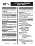
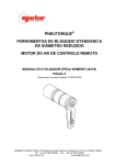
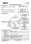
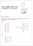
OPERATOR’S MANUAL
NORBAR TORQUE TOOLS LTD
Beaumont Road, Banbury,
Oxfordshire, OX16 1XJ
UNITED KINGDOM
Tel + 44 (0)1295 270333
Email [email protected]
NORBAR TORQUE TOOLS PTE LTD
194 Pandan Loop
#07-20 Pantech Business Hub
SINGAPORE 128383
Tel + 65 6841 1371
Email [email protected]
NORBAR TORQUE TOOLS PTY LTD
45–47 Raglan Avenue, Edwardstown,
SA 5039
AUSTRALIA
Tel + 61 (0)8 8292 9777
Email [email protected]
NORBAR TORQUE TOOLS (SHANGHAI) LTD
E Building–5F, no. 1618 Yishan Road,
Minhang District, Shanghai
CHINA 201103
Tel + 86 21 6145 0368
Email [email protected]
NORBAR TORQUE TOOLS INC
36400 Biltmore Place, Willoughby,
Ohio, 44094
USA
Tel + 1 866 667 2279
Email [email protected]
NORBAR TORQUE TOOLS INDIA PVT. LTD
Plot No A-168, Khairne Industrial Area,
Thane Belapur Road, Mahape,
Navi Mumbai – 400 709
INDIA
Tel + 91 22 2778 8480
Email [email protected]
SUPPORTED TORQUE CALIBRATION BEAM
www.norbar.com
NORBAR TORQUE TOOLS (NZ) LTD
B3/269A Mt Smart Road
Onehunga, Auckland 1061
NEW ZEALAND
Tel + 64 9579 8653
Email [email protected]
© Norbar Torque Tools Ltd 2007
Part Number 34320 | Issue 4 | Original Instructions (English)
CONTENTS
Part Numbers Covered by This Manual
2
Safety
2
Introduction
Parts Included
Accessories
2
2
2
Features and Functions
3
External Effects
Temperature Compensation
Gravitational Effects
Buoyancy Effects
3
3
4
4
Set up Instructions
Fixing Pedestal
Beam & Bearing Support
Levelling Gearbox
Hangers
5
5
6
7
7
Operating Instructions
Locating Transducer
Locating Hangers
Exercising
Calibration
8
8
9
10
10
Maintenance
Beam Repair & Recalibration
Weight Recalibration
11
11
11
Specifications
12
Trouble shooting
12
Glossary of terms
12
1
PART NUMBERS COVERED BY THIS MANUAL
Torque
Part Number
N∙m
500 - 5000
21842
lbf∙ft
500 – 5000
SAFETY
It is recommended that safety shoes are worn. Use safe manual handling techniques when lifting.
INTRODUCTION
This calibration beam is designed for the static calibration of torque transducers. Torque is generated by the
application of a known force (weights) at a known radius from the centre of rotation of the torque transducer.
Reaction is taken via a levelling gearbox so the beam can be kept horizontal.
Parts Included
FIGURE 1 – Parts Included
Description
Beam with bearing support
Pedestal with bed
Levelling gearbox
Jacking plate
Torque wrench
M8 Bolt (25354.90)
(Bearing support to pedestal)
M6 Bolt (25353.25)
(Guide plate to bed)
Quantity
1
1
1
2
1
2
4
Description
Guide plate
Hangers
Weight platform
Raw bolts
Calibration certificate
M12 Bolt (25356.35)
(Bearing support to pedestal)
Quantity
2
2
1
4
1
Operator’s Manual
1
Accessories
Part Number
21469.NAM
2
Description
Set of 20 x 50 lbf weights to give 5000 N∙m / 5000 lbf∙ft
6
FEATURES AND FUNCTIONS
Transducer Compatibility
The calibration beam is ideally suited to Norbar torque transducers, but may be used on other
manufacturer's equipment.
Beam Alignment
A self-locking gearbox provides an easy method of keeping the beam horizontal once loaded.
Traceability
The beams and weights are guaranteed within a tolerance of accuracy and traceable certification is provided.
Torque Accuracy
The beam and its associate stand have been robustly constructed to ensure only torque is applied to the
transducer under test. Any torque losses (through bending or bearing loss) seen by the transducer have
been minimised. Weight accuracy is required to be equal to or better than 0.01% which approximates to
class M1.
Clockwise / Counter Clockwise Operation
The symmetrical beams allow for both clockwise and counter clockwise calibration.
EXTERNAL EFFECTS
Temperature Compensation
The calibration beam should be used in a temperature controlled environment of 20°C +/- 2°C.
If the beam must be used outside these limits, the temperature must be stable (within 1°C change per hour)
and the effective length of the beam calculated according to the details below.
-6
The Coefficient of linear expansion for steel is 12 x 10 / °C or (0.000012 per °C)
The formula for calculating the change in effective beam length is:
Change in length =
Initial beam radius x Coefficient of linear expansion x Change in temperature in °C (from 20°C Nominal)
Example: 1 metre radius beam used at 24 °C.
-6
Change in length = Initial beam radius x (12 x 10 ) x 4
-6
Change in length = 1 x (12 x 10 ) x 4
-5
Change in length = 4.8 x 10
Change in length = 0.000048 metre
New effective beam radius = Initial beam radius + Change in length
New effective beam radius = 1.000048 metre
Example: 1 metre radius beam used at 16 °C.
-6
Change in length = Initial beam radius x (12 x 10 ) x -4
-6
Change in length = 1 x (12 x 10 ) x -4
-5
Change in length = -4.8 x 10
Change in length = -0.000048 metre
New effective beam radius = Initial beam radius + Change in length
New effective beam radius = 0.999952 metre
3
Gravitational Effects
It is very important that the gravitational value for the Laboratory is established. The effect of not doing this in
the UK could be a variation in the force produced by the weight of up to approximately 0.05%, which is five
times the 0.01% tolerance of the weight. Outside of the UK this variation in force could be significantly more.
It is therefore strongly recommended that you establish the local value of gravity (g) for your Laboratory and
use weights that have been calibrated at that gravitational constant.
Norbar will supply weights calibrated to gravitational constants specified by the customer. However, if the
customer does not specify a value for ‘g’, the value can be calibrated at an estimated gravitational constant
for the customer’s location. This will be agreed with the customer prior to calibration.
Buoyancy Effects
The Norbar system uses calibrated weights to generate a downwards force.
This means that Archimedes principle applies, i.e. air pressure under the weights causes an upwards force.
This reduces the effective force generated by the weights and therefore the mass must be increased to allow
for this.
3
Under standard conditions (i.e. Air density 1.2 kg/m and 20°C and working in conventional mass terms) the
increase required is by a factor of 0.015%. Weights purchased from Norbar will already have this factor taken
into account.
Weights that are calibrated to standard procedures do not have this factor taken into account because the air
buoyancy affects both sides of the mass balance and can be ignored. It is important that weights used for
torque transducer calibration are adjusted for air buoyancy.
It should also be noted that the double ended beam design employed by Norbar means that each half of the
beam is balanced with regard to buoyancy of the beam. This is a significant advantage over single-arm
counterbalanced systems.
4
SET UP INSTRUCTIONS
The set up of this beam covers the following items:
1. Fixing Pedestal.
2. Beam & Bearing Support.
3. Levelling Gearbox.
4. Hangers.
NOTE:
The set up instructions must be followed in the sequence shown.
Items required:
Spanner set.
Allen key set.
Spirit level (recommended accuracy +/-0.5 mm/m)
4 x Suitable fixing bolts & Drill (to suit fixing bolts).
1. Fixing Pedestal
1.1
Ensure the floor is flat, clean and capable of supporting a weight of 480 Kg.
1.2
Position pedestal to allow access around the calibration beam when assembled.
NOTE:
Fixing bolts NOT included.
Customer must supply 4 off M10 Fixing bolts to suit their concrete floor.
Pull out force on fixing bolts must exceed 2.5 kN.
Ensure the concrete floor is capable of taking 30 N/mm².
Tighten fixing bolts to achieve a minimum of 6 kN tension in the bolts.
1.3
Drill concrete floor to accept the fixing bolts.
Fit fixing bolts to hold pedestal to floor, do not fully tighten yet.
1.4
Locate jacking plates (supplied) under jacking screws, as shown in figure 2.
FIGURE 2 – Pedestal Base with Fixing Holes & Jacking Screws
1.5
Place a spirit level on the machined surface of the pedestal bed and adjust jacking screws to ensure
pedestal is level. For correct calibration it is essential the pedestal is level in all directions.
1.6
Fully tighten the raw bolts to the required torque.
1.7
Check pedestal bed is level.
5
2. Beam & Bearing Support
WARNING:
2.1
THE BEAM & BEARING SUPPORT IS HEAVY.
THIS TASK REQUIRES MORE THAN 1 PERSON.
Line up the bearing support with holes in the middle of the bed.
FIGURE 3 – Location of Beam & Bearing Support
2.2
Position of beam is established by fitting bearing support with 2 off M8 shoulder bolts supplied. Tighten
to 10 N∙m.
2.3
Fix using 6 off M12 bolts supplied. Tighten to 80 N∙m.
2.4
Fit 2 off guide plates to bed. Tighten 4 off M8 bolts to 10 N∙m.
6
3. Levelling Gearbox
3.1
Remove M6 end stop screw from pedestal bed.
3.2
Line up the levelling gearbox with the slots in the pedestal bed then slide on.
Ensure drive square input is facing beam as shown in figure 4.
FIGURE 4 – Location of Levelling Gearbox
3.3
Fit M6 end stop screw to pedestal bed.
4. Hangers
TIP:
The hangers are supplied ready to attach to the beam.
Ensure the correct hanger is fixed to the correct end of the beam.
If the hanger assembly is taken apart, DO NOT mix parts with the other hanger assembly.
4.1
Bolt hanger marked “XX” to beam end marked “XX”.
Bolt hanger marked “YY” to beam end marked “YY”.
Choose a location (A, B, C, D, E, F, G or H) for each beam, the required location is set in the
Operating Instructions.
4.2
Place weight platform under hanger to be loaded, as shown in figure 5.
FIGURE 5 – Hanger Weight Platform
7
OPERATING INSTRUCTIONS
WARNING:
KEEP HANDS CLEAR OF MOVING PARTS DURING USE.
FIGURE 6 – Location of Transducer
TIP:
This is a general procedure to use the calibration beam.
Use this procedure along with any specific standard being followed.
Locating Transducer
1.
Connect transducer to display unit required. Zero reading on display.
2.
Mount the transducer between beam & levelling gearbox using appropriate adaptors, see figure 6. Slide
the levelling gearbox so the transducer drive squares are fully engaged.
3.
Allow the required warm up time for transducer & display; a minimum twenty (20) minutes is
recommended.
8
Locating Hangers
FIGURE 7 – Beam Location Holes
1.
The beam has many location holes for the hangers, see figure 7. The required location depends on the
torque required & the weights used. Use the following table to determine the hanger location.
Location
A
B
C
D
E
F
G
H
Distance
Force
m
ft
N
lbf
Torque
(Force x Distance)
1.52400
1.34885
1.12404
0.899236
0.786832
1.21920
1.00000
0.91440
5
4
3
4,448.22
4,448.22
4,448.22
4,448.22
4,448.22
4,448.22
*
4,448.22
1000
1000
1000
1000
1000
1000
*
1000
5000 lbf∙ft
6000 N∙m
5000 N∙m
4000 N∙m
3500 N∙m
4000 lbf∙ft
*
3000 lbf∙ft
Absolute
maximum torque
for overload test
110%
110%
110%
110%
110%
110%
110%
110%
* = For use with metric weights.
2.
Bolt the hangers to the required location.
Ensure that the correct hanger is located at each end of the beam.
3.
Place weight platform, figure 5, under hanger to be loaded.
NOTE:
The hangers must be loaded equally, so weights are added in pairs.
9
Exercising
1.
It is recommended to exercise the transducer before calibration; this can be done by loading to full scale
then removing the weights three (3) times.
The display output should be watched during this process to avoid overloading.
The exercising procedure is:
A.
Apply torque by adding the required weights to the hangers, then winding the handle on the levelling
gearbox until full scale torque is displayed.
B.
Decrease torque by un-winding the handle on the levelling gearbox until the display reads the
minimum value and weights are firmly seated on weight platform.
C.
Repeat steps A & B two more times.
D.
Remove all weights.
E.
Ensure transducer display is set to zero before calibration.
The levelling gearbox may need to be removed from the transducer to get a true zero.
Calibration
1.
The transducer is loaded in the required increments.
Gentle application of the weights is advised to maintain a steady reading.
At each torque increment the procedure is:
A.
Place weights onto hangers, loading the twin hangers equally.
B.
Wind the handle on the levelling gearbox to lift the weights clear of the weight platform.
C.
Level beam using the levelling gearbox.
Ensure the beam spirit level reads correctly, see figure 8.
D.
Waiting for the reading to stabilise.
E.
Take torque reading from display.
F.
The next torque increment can be taken.
G.
After the last increment remove all weights.
Remove levelling gearbox from transducer.
A final zero result can be measured.
FIGURE 8 – Beam Spirit Level
NOTE:
If the transducer needs adjusting refer to appropriate operator’s manual or service manual.
NOTE:
For reverse calibration the weights are applied to the opposite hangers. The transducer will
need to be exercised in the reverse direction before calibration.
10
MAINTENANCE
Beam Repair & Recalibration
Norbar Supported Calibration Beams are designed for transducer calibration at low levels of uncertainty.
They are robust for normal handling by technicians, but if dropped or otherwise damaged, may lose their
calibration integrity. It is therefore essential that the beam is recalibrated after any such incident.
Recalibration involves establishing the beam length from the centre of the driving square to a locus of points
on the beam end. (See original calibration certificate for further details). This is difficult to achieve with
conventional length standards, although use of a Co-ordinate Measuring Machine may give satisfactory
results. Planned calibration intervals will depend on usage, and should be decided by the laboratory.
Norbar offers a full repair and recalibration service, with traceable certification of status before and after
repair. Due to the complex nature of the beams, please contact Norbar in the event of any damage requiring
repair.
Weight Recalibration
It should be possible to obtain local recalibration of weight sets. Please contact Norbar if further assistance is
required.
11
SPECIFICATIONS
Absolute maximum torque:
110% (for each beam location).
Recommended temperature:
20°C +/- 2°C.
Humidity:
30% to 70%.
Location hole accuracy:
+/- 0.01% of nominal.
TROUBLE SHOOTING
Problem
Can not achieve zero torque.
Solution
Levelling gearbox causing small load, remove levelling gearbox.
GLOSSARY OF TERMS
Term
Bearing Support
Class M1
Hanger
Pedestal
Weight Platform
Levelling Gearbox
12
Meaning
Centre of beam rotation.
Weight classification.
Device to hold weights.
Main support for calibration beam.
Device to rest weights on between tests.
Device to ensure beam is level.
OPERATOR’S MANUAL
NORBAR TORQUE TOOLS LTD
Beaumont Road, Banbury,
Oxfordshire, OX16 1XJ
UNITED KINGDOM
Tel + 44 (0)1295 270333
Email [email protected]
NORBAR TORQUE TOOLS PTE LTD
194 Pandan Loop
#07-20 Pantech Business Hub
SINGAPORE 128383
Tel + 65 6841 1371
Email [email protected]
NORBAR TORQUE TOOLS PTY LTD
45–47 Raglan Avenue, Edwardstown,
SA 5039
AUSTRALIA
Tel + 61 (0)8 8292 9777
Email [email protected]
NORBAR TORQUE TOOLS (SHANGHAI) LTD
E Building–5F, no. 1618 Yishan Road,
Minhang District, Shanghai
CHINA 201103
Tel + 86 21 6145 0368
Email [email protected]
NORBAR TORQUE TOOLS INC
36400 Biltmore Place, Willoughby,
Ohio, 44094
USA
Tel + 1 866 667 2279
Email [email protected]
NORBAR TORQUE TOOLS INDIA PVT. LTD
Plot No A-168, Khairne Industrial Area,
Thane Belapur Road, Mahape,
Navi Mumbai – 400 709
INDIA
Tel + 91 22 2778 8480
Email [email protected]
SUPPORTED TORQUE CALIBRATION BEAM
www.norbar.com
NORBAR TORQUE TOOLS (NZ) LTD
B3/269A Mt Smart Road
Onehunga, Auckland 1061
NEW ZEALAND
Tel + 64 9579 8653
Email [email protected]
© Norbar Torque Tools Ltd 2007
Part Number 34320 | Issue 4 | Original Instructions (English)