1
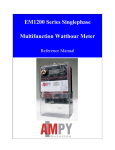
MADE IN
THE USA
August, 2011
E-Z RIDER®
HEAVY DUTY CLUTCHES
FOR ALL MEDIUM &
HEAVY DUTY VEHICLES
Call Toll Free:
1-800-325-6138
Visit Our Website:
www.ACE-MFG.com
300 Ramsey Street, Sullivan, MO 63080 • Ph. (573)468-4181 • Fax (573)468-5584
TABLE OF CONTENTS
Benefits & Features ......................................................................................................... 3
Cryogenic Treated Disc Springs ...................................................................................... 4
Friction Material Comparison ........................................................................................... 5
Determining Proper Clutches........................................................................................... 6
E-Z Clutch Selection Guide ............................................................................................. 7
Medium Duty Clutches
14” x 1-3/4” ....................................................................................................................... 8
14” x 2”............................................................................................................................. 9
Heavy Duty Clutches
14” x 1-3/4” ..................................................................................................................... 10
14” x 2”........................................................................................................................... 11
15-1/2” x 2” 8 Spring ...................................................................................................... 12
15-1/2” x 2” 10 Spring .................................................................................................... 13
15-1/2” x 2” 7 & 9 Spring ................................................................................................ 14
TABLE OF CONTENTS
Flywheels
Caterpillar ...................................................................................................................... 15
Cummins .................................................................................................................. 16-17
Detroit ............................................................................................................................ 18
Ford-Sterling .................................................................................................................. 18
Mack .............................................................................................................................. 19
Navistar-International ..................................................................................................... 20
Clutch Accessories ................................................................................................... 21-24
Installation Guidelines ..............................................................................................25-28
Adjustment Procedure ..............................................................................................29-30
Maintenance Tips .......................................................................................................... 31
Engine Horsepower & Torque Ratings ......................................................................32-40
Quick Reference ............................................................................................................ 41
Top 10 Selling ............................................................................................................... 42
Notes ............................................................................................................................ 43
2
Call Toll Free: 1-800-325-6138
®
E-Z
RIDER
Heavy Duty Clutches, Flywheels & Clutch Accessories
• No cores to handle—Because we are the manufacturer, only new parts and
assemblies are used. E-Z Rider clutch units are manufactured and assembled
in the U.S.A. at our Sullivan, Missouri (St. Louis) facility.
• The Ace E-Z Rider series clutch has the easiest pedal action of any new
clutch on the market. Ace maintains a number of design and process patents to
achieve the soft pedal.
• Dual adjust feature—Every Ace clutch incorporates the E-Z adjust feature and
the manual adjust capability.
• Disc springs—Every Ace E-Z Rider clutch unit is shipped with disc that
contain chrome silicon, valve quality steel disc springs that have been
cryogenically treated. A patented process that is exclusive to Ace. This
process has eliminated spring failures.
• Friction Material—Ace offers asbestos-free woven organic, proprietary sintered
copper, and iron materials of high friction properties which results in low wear
and high reliability. Test results show increased clutch life and less wear to the
mating parts with the iron based buttons.
• State of the art assembly—Unlike the competition, every Ace clutch unit is
shipped as a “serialzed” matched unit and digitally recorded to the specific
serial number.
• Mack application—As part of the E-Z Rider series, we offer EZ208935-51
and the EZ208935-51H heavy duty version of the Mack 9 spring clutch unit.
New 9 spring units have typically been reserved exclusive to the Mack
dealer program.
E-Z RIDER®
• Fiber Brake Spacer—Shipped free of charge in every new Ace clutch unit.
The spacer is essential to achieve brake squeeze when the flywheel has
been resurfaced.
• Cast cover replacement—Ace offers a cast cover replacement for the medium
duty stamped steel “throw away” clutch.
• Training and fieldwork—Ace will provide training and hold clutch clinics free
of charge. Our techs will happily troubleshoot an installation or failure.
• Warranty—All Ace clutch units offer 12 months and unlimited mileage warranty
against defects in material and workmanship.
www.ACE-MFG.com
3
Cryogenic Treated Disc Springs
A patented process exlusive to Ace EZ Rider Clutches
One of the many selling features of Ace’s
E-Z Rider series clutch units is an exclusive
patented process of Cryo treating our disc
springs. Unlike most clutch manufacturers and
rebuilders, we start with a chrome-silicon, valve
quality spring. With the combination of higher
quality steel and cryo treating, we have virtually
eliminated disc spring failure.
Our cryogenic process involves taking springs slowly down to -300f. The
temperature cycle is regulated by a computer controlled flow of nitrogen into the
chamber where the parts are placed. After the disc springs are returned to room
temperature they are placed in a tempering furnace and tempered to a setting
of +300f/400f.
A variety of improvements are gained, such as stress relief, wear resistance, and
fatigue life. Testing reflects an increase in spring life from 2 to 5 times that of an
untreated spring.
CRyOGENIC DISC SPRINGS
The Theory; The cryogenic process most commonly applies to heat treated
steels. Heat treated steels are stronger and harder. Heat treating is a process of
heating the steel, quenching in oil or water and draw tempering. Steel is comprised of austenite grain which is soft and weak. The quenching transforms the
austenite into harder and stronger martensite. The martensite becomes too brittle
in this state for most heat treated steels. By elevating the temperature again ....
but to a lower than orignal temperature that it was originally tempered makes the
martensite less brittle yet stronger and harder. During this process, the austenite
is not completely changed into martensite. The “retained”austenite may still make
up more than 5% of the quenched and tempered structure
in the steel. By cryogenically treating the steel, the austenite is transformed into martensite so that the structure
is 100% martensite. It is believed the cryogenic process
causes atoms to diffuse or migrate to these voids and fill
them, creating a more homogenious grain structure that
aids in improved properties.
We also use this process for all our tools such as dies,
punches, drills, taps, broaches and cutting inserts.
Depending on the parts being treated, Ace recognizes
a 50-300 percent increase in performance life of our tools.
4
Call Toll Free: 1-800-325-6138
Friction Material Comparison
Best
Pros - More aggressive, higher torque, low wear
Cons - Rough on mating surfaces
Ceramics
r
e
t
t
e
B
Cons - Lower coefficient than ceramic, lower
torque than ceramic
Iron Base
Good
Pros - Smooth engagements, light-medium duty,
excellent on mating surfaces, not recommended for 300 + HP engines
FRICTION MATERIAL
Pros - Better heat resistance, smoother
engagement than ceramic, good wear,
easy on mating surfaces
Cons - Low torque
Woven Non Asbestos Organic
www.ACE-MFG.com
5
Determining The Proper Clutch
For Your Vehicle
1. Determine the size of the clutch. (14” or 15.5”)
2. If 15.5”, then measure the center flywheel opening. (Dimension *A in the
illustration) Approximate flywheels sizes: 7”, 8.5” or 10”
3. Determine engine torque at current settings. (See Page 32-Torque Chart)
A. If flywheel bore is 7”, ONLY use an 8 spring disc.
B. If flywheel bore is 8.5”, use a 10 spring disc.
C. If flywheel bore is 10”, use a 7 spring, 6 spring (VCT), or a 9 spring (Mack Only).
D. If you have a 10” flywheel bore, DO NOT USE ORGANIC FACING. The facing
I.D. will extend into the flywheel bore opening, not having full facing contact.
PROPER CLuTCh
6
Call Toll Free: 1-800-325-6138
E-Z RIDER®
E-Z Clutch Selection Guide
CLUTCH MODELS TO USE BY FLYWHEEL BORE SIZE
14” Clutches
All 14” clutches use 8 spring disc assemblies and can be used only with
7” flywheel bore size.
15-1/2” Clutches
Disc types will vary and are designed to be used with a specific flywheel bore
size. Shown below are the E-Z RIDER® and STANDARD clutch models
designed for each bore size.
E-Z RIDER® Clutch choices
EZ208391-77B
EZ208391-81B
EZ208391-82B
Standard Clutch choices
107390-77
107390-80
107391-77B
107391-81B
107391-82B
7”
7.25
BORE
E-Z RIDER® Clutch choices
EZ208391-74B
EZ208391-78B
EZ208391-93B
EZ208391-93H
Standard Clutch choices
107391-74B
107391-78B
107391-93B
8.5”
8.562
BORE
10 Spring Disc
E-Z RIDER® Clutch choices
EZ208925-82B
EZ208925-82H
EZ208935-51 (Mack)
EZ208935-51H (Mack)
Standard Clutch choices
107925-82B
107935-51 (Mack)
10”
9.750
BORE
E-Z CLuTCh GuIDE
8 Spring Disc
7 & 9 Spring Disc
*For non-standard requirements and/or selection of the specific model for a vehicle,
follow the clutch selection procedure in the catalog.
E-Z Rider® is a registered trademark of Ace Mfg. & Parts Co. Inc., Sullivan, MO USA
www.ACE-MFG.com
7
Heavy Duty Clutch for Medium Duty Truck
14” x 1-3/4” For 14” Flat Flywheel
H.D. Cast Version of Stamped Steel
Dual Disc
14” hEAVy DuTy CLuTChES
TORQUE
PLATE LD
900
3600
TORQUE
PLATE LD
950
3600
TORQUE
PLATE LD
620
3600
TORQUE
PLATE LD
680
3600
680
3600
DISC STYLE
PEDAL
ADJ
PART NUMBER
COMMENTS
EZ
EZ
EZ107237-8CB
Available With
Iron Buttons
PEDAL
ADJ
PART NUMBER
COMMENTS
EZ
EZ
EZ107237-4CB
Available With
Iron Buttons
PEDAL
ADJ
PART NUMBER
COMMENTS
EZ
EZ
EZ107683-5CB
Available With
Iron Button
PEDAL
ADJ
PART NUMBER
COMMENTS
Ceramic 8 Spring
4 Pad Co - Ft
EZ
EZ
EZ107915-1CB
Available With
Iron Button
Mercedes
Ceramic 8 Spring
4 Pad Co - Ft
EZ
EZ
EZ107683-4CB
Available With
Iron Button
Ceramic 8 Spring
3 Pad Co - Ft
DISC STYLE
Ceramic 8 Spring
4 Pad Co - Ft
Single Disc
DISC STYLE
Ceramic 8 Spring
3 Pad Co - Ft
DISC STYLE
Ace Mfg. & Parts Co. manufactures the parts shown above. Spicer® is a registered trademark of Dana Corp.
E-Z Rider® is a registered trademark of Ace Mfg. & Parts Co. Inc., Sullivan, MO USA
Note: These clutches are not adjusted for synchronized transmissions.
8
Call Toll Free: 1-800-325-6138
Heavy Duty Clutch for Medium Duty Truck
14” x 2” For 14” Flat Flywheel
H.D. Cast Version of Stamped Steel
TORQUE
PLATE LD
900
3600
TORQUE
PLATE LD
950
3600
DISC STYLE
Ceramic 8 Spring
3 Pad Co - Ft
DISC STYLE
Ceramic 8 Spring
4 Pad Co - Ft
PEDAL
ADJ
PART NUMBER
COMMENTS
EZ
EZ
EZ107686-2CB
Available With
Iron Buttons
PEDAL
ADJ
PART NUMBER
COMMENTS
EZ
EZ
EZ107686-4CB
Available With
Iron Buttons
The Medium Truck Heavy Duty Cluch
DO YOU WANT
-OR- NEW TECHNOLOGY
OLD TECHNOLOGY
EXTENDED MILEAGE
STAMPED STEEL
CLUTCH WITH CAST COVER!
LIMITED MILEAGE
YES!
“THROW AWAY” CLUTCH?
NO!
14” hEAVy DuTy CLuTChES
Dual Disk
Ace Mfg. & Parts Co. manufactures the parts shown above. Spicer® is a registered trademark of Dana Corp.
Note: These clutches are not adjusted for synchronized transmissions.
www.ACE-MFG.com
9
14” x 1-3/4” Recess (Pot) Flywheel
TORQUE
PLATE LD
DISC STYLE
PEDAL
ADJ
PART NUMBER
COMMENTS
1150
3600
Organic 8 Springs
Co - Ft
EZ
DUAL
EZ108035-82B
1150
3600
Organic 8 Springs
Co - Ft
STD
STD
107035-82B
TORQUE
PLATE LD
DISC STYLE
PEDAL
ADJ
PART NUMBER
COMMENTS
1400
3600
Ceramic 8 Springs
4 Pad Co - Ft
EZ
DUAL
EZ108063-59A
Available With
Iron Button
1400
3600
Ceramic 8 Springs
4 Pad Co - Ft
STD
STD
107063-59A
14” hEAVy DuTy CLuTChES
Ace Mfg. & Parts Co. manufactures the parts shown above. Spicer® is a registered trademark of Dana Corp.
E-Z Rider® is a registered trademark of Ace Mfg. & Parts Co. Inc., Sullivan, MO USA
10
Call Toll Free: 1-800-325-6138
14” x 2” Recess (Pot) Flywheel
S
Er t
V
O
O
r C St, N EEL!
u
O CA St
E
Ar mpEd
StA
TORQUE
PLATE LD
DISC STYLE
PEDAL
ADJ
PART NUMBER
COMMENTS
1250
3600
Ceramic 8 Springs
3 Pad Co - Ft
EZ
DUAL
EZ108034-61B
Available With
Iron Button
1250
3600
Ceramic 8 Springs
3 Pad Co - Ft
STD
STD
107034-61B
TORQUE
PLATE LD
DISC STYLE
PEDAL
ADJ
PART NUMBER
1150
3600
Organic 8 Springs
Co - Ft
EZ
DUAL
EZ108034-82B
1150
3600
Organic 8 Springs
Co - Ft
STD
STD
107034-82B
TORQUE
PLATE LD
DISC STYLE
PEDAL
ADJ
PART NUMBER
COMMENTS
1400
3600
Ceramic 8 Springs
4 Pad Co - Ft
EZ
DUAL
EZ108050-59B
Heavy Duty
Plate
Available With
Iron Button
1400
3600
Ceramic 8 Springs
4 Pad Co - Ft
STD
STD
107050-59B
Heavy Duty
Plate
1400
3600
Ceramic 8 Springs
4 Pad Co - Ft
EZ
DUAL
EZ108050-69B
Standard Plate
Available With
Iron Button
1400
3600
Ceramic 8 Springs
4 Pad Co - Ft
STD
STD
107050-69B
Standard Plate
14” hEAVy DuTy CLuTChES
COMMENTS
Ace Mfg. & Parts Co. manufactures the parts shown above. Spicer® is a registered trademark of Dana Corp.
E-Z Rider® is a registered trademark of Ace Mfg. & Parts Co. Inc., Sullivan, MO USA
www.ACE-MFG.com
11
15-1/2” x 2” 8 Spring 7” Flywheel Bore
15-1/2” hEAVy DuTy CLuTChES
TORQUE
PLATE LD
DISC STYLE
PEDAL
ADJ
PART NUMBER
COMMENTS
1250
3600
Organic 8 Springs
Co - Ft
EZ
DUAL
EZ208391-77B
1250
3600
Organic 8 Springs
Co - Ft
STD
STD
107391-77B
1400
4000
Organic 8 Springs
Co - Ft
EZ
DUAL
EZ208391-82B
1400
4000
Organic 8 Springs
Co - Ft
STD
STD
107391-82B
TORQUE
PLATE LD
DISC STYLE
PEDAL
ADJ
PART NUMBER
COMMENTS
1400
3600
Ceramic 8 Spring
4 Pad Co - Ft
EZ
DUAL
EZ208391-81B
Available With
Iron Button
1400
3600
Ceramic 8 Spring
4 Pad Co - Ft
STD
STD
107391-81B
Ace Mfg. & Parts Co. manufactures the parts shown above. Spicer® is a registered trademark of Dana Corp.
E-Z Rider® is a registered trademark of Ace Mfg. & Parts Co. Inc., Sullivan, MO USA
12
Call Toll Free: 1-800-325-6138
15-1/2” x 2” 10 Spring 8.5” Flywheel Bore
PLATE LD
DISC STYLE
PEDAL
ADJ
PART NUMBER
COMMENTS
1450
4000
Organic 10 Spring
Co - Ft
EZ
DUAL
EZ208391-78B
1450
4000
Organic 10 Spring
Co - Ft
STD
STD
107391-78B
TORQUE
PLATE LD
DISC STYLE
PEDAL
ADJ
PART NUMBER
COMMENTS
1650
3600
Ceramic 10 Spring
4 Pad Co - Ft
EZ
DUAL
EZ208391-74B
Available With
Iron Button
1650
3600
Ceramic 10 Spring
4 Pad Co - Ft
STD
STD
107391-74B
1860
4000
Ceramic 10 Spring
4 Pad Co - F
EZ
DUAL
EZ208391-93B
1860
4000
Ceramic 10 Spring
4 Pad Co - Ft
STD
STD
107391-93B
TORQUE
PLATE LD
DISC STYLE
PEDAL
ADJ
PART NUMBER
COMMENTS
2050
4000
Ceramic 10 Spring
6 Pad Co - Ft
EZ
DUAL
EZ208391-93H
Available With
Iron Button
Available With
Iron Button
15-1/2” hEAVy DuTy CLuTChES
TORQUE
Ace Mfg. & Parts Co. manufactures the parts shown above. Spicer® is a registered trademark of Dana Corp.
www.ACE-MFG.com
13
15-1/2” x 2” 7 Spring 10” Flywheel Bore
TORQUE
PLATE LD
DISC STYLE
PEDAL
ADJ
PART NUMBER
COMMENTS
1700
3600
Ceramic 7 Spring
4 Pad Co - Ft
EZ
DUAL
EZ208925-82B
Available With
Iron Button
1700
3600
Ceramic 7 Spring
4 Pad Co - Ft
STD
STD
107925-82B
TORQUE
PLATE LD
DISC STYLE
PEDAL
ADJ
PART NUMBER
COMMENTS
2050
4000
Ceramic 7 Spring
6 Pad Co - Ft
EZ
DUAL
EZ208925-82H
Available With
Iron Button
15-1/2” hEAVy DuTy CLuTChES
15-1/2” x 2” 9 Spring 10” Flywheel Bore
TORQUE
PLATE LD
DISC STYLE
PEDAL
ADJ
PART NUMBER
COMMENTS
1700
3600
Ceramic 9 Spring
4 Pad Co - Ft
EZ
DUAL
EZ208935-51
Mack Only
Available With
Iron Button
1700
3600
Ceramic 9 Spring
4 Pad Co - Ft
STD
STD
107935-51
Mack Only
TORQUE
PLATE LD
DISC STYLE
PEDAL
ADJ
PART NUMBER
COMMENTS
2050
4000
Ceramic 9 Spring
6 Pad Co - Ft
EZ
DUAL
EZ208935-51H
Mack Only
Available With
Iron Button
Ace Mfg. & Parts Co. manufactures the parts shown above. Spicer® is a registered trademark of Dana Corp.
14
Call Toll Free: 1-800-325-6138
ACE CATALOG # AF4P4797
ACE CATALOG # AF9Y9311
ACE CATALOG # AF1265875
www.ACE-MFG.com
DESCRIPTION
APPLICATION
15” FLAT FLYWHEEL
10” BORE
12 MOUNTING BOLT HOLES
*USE 7 SPRING CLUTCH
BEARING # AB197 (6306)
20” RING GEAR 113 TEETH
RING GEAR # AF4N2514
CAT
3406/3406E
DESCRIPTION
APPLICATION
14” FLAT FLYWHEEL
7” BORE
10 MOUNTING BOLT HOLES
*USE WITH 8 SPRING CLUTCH
BEARING # AB199 (6305) OR AB190
(6206)RING GEAR # AF9L8113
RING GEAR #968113
17” RING GEAR 134 TEETH
CAT
3208
DESCRIPTION
APPLICATION
14” FLAT FLYWHEEL
7” BORE
8 MOUNTING BOLT HOLES
1 DOWEL PINHOLE
BEARING # AB190 (6206-2RS)
17” RING GEAR 134 TEETH
RING GEAR # 7W5095
CAT
3116/3126
FLyWhEELS-CATERPILLAR
Flywheels
15
Flywheels
ACE CATALOG # AF3016495
ACE CATALOG # AF3021660
FLyWhEELS-CuMMINS
16
ACE CATALOG # AF3042787
DESCRIPTION
APPLICATION
14” POT FLYWHEEL
7” BORE
6 MOUNTING BOLT HOLES
*USE 8 SPRING CLUTCH
BEARING # AB197 (6306)
DRIVE PINS NOT INCLUDED
17” RING GEAR 103 TEETH
RING GEAR # AF4797
CUMMINS
NT855
SMALL CAM
BIG CAM
DESCRIPTION
APPLICATION
15” FLAT FLYWHEEL
8.5” BORE
6 MOUNTING BOLT HOLES
*USE 10 SPRING CLUTCH
BEARING # AB197 (6306)
17” RING GEAR 103 TEETH
RING GEAR # 4797
CUMMINS
NT855/N14
DESCRIPTION
APPLICATION
14” POT FLYWHEEL
7” BORE
8 MOUNTING BOLT HOLES
*USE 8 SPRING CLUTCH
BEARING # AB197 (6306)
DRIVE PINS NOT INCLUDED
17” RING GEAR 103 TEETH
RING GEAR # AF4797
CUMMINS
L10/M11
Call Toll Free: 1-800-325-6138
ACE CATALOG # AF3071535
ACE CATALOG # AF3071615
ACE CATALOG # AF3921263
www.ACE-MFG.com
DESCRIPTION
APPLICATION
15” FLAT FLYWHEEL
10” BORE
6 MOUNTING BOLT HOLES
*USE 7 SPRING CLUTCH
BEARING # AB197 (6306)
17” RING GEAR 103 TEETH
RING GEAR # AF4797
CUMMINS
NT855
N14
DESCRIPTION
APPLICATION
15” FLAT FLYWHEEL
10” BORE
8 MOUNTING BOLT HOLES
*USE 7 SPRING CLUTCH
BEARING # AB197 (6306)
RING GEAR # AF4797
17” RING GEAR 103 TEETH
CUMMINS
M11
DESCRIPTION
APPLICATION
14” FLYWHEEL
7” BORE
8 MOUNTING BOLT HOLES
*USE 8 SPRING CLUTCH
BEARING # AB190 (6206)
RING GEAR # AF3903309
173 TEETH
CUMMINS
5.9-B
FLyWhEELS-CuMMINS
Flywheels
17
Flywheels
ACE CATALOG # AF23509709
ACE CATALOG # AF8922126
FLyWhEELS-DETROIT/FORD
18
DESCRIPTION
APPLICATION
15” FLAT FLYWHEEL
10” BORE
12 MOUNTING BOLT HOLES
*USE 7 SPRING CLUTCH
BEARING # AB197 (6306)
20” RING GEAR 118 TEETH
RING GEAR # AF5166664
DETROIT
SERIES 60
DESCRIPTION
APPLICATION
14” FLYWHEEL
7” BORE
8 MOUNTING BOLT HOLES
*USE 8 SPRING CLUTCH
BEARING # AB195 (6205)
17” RING GEAR 138 TEETH
RING GEAR # AF5116302
DETROIT
8.2
Ford-Sterling
ACE CATALOG # AFE7HZ6375A
DESCRIPTION
APPLICATION
14” FLAT FLYWHEEL
7” BORE
8 MOUNTING BOLT HOLES
*USE 8 SPRING CLUTCH
BEARING # AB190 (6206)
17” RING GEAR 138 TEETH
RING GEAR # AFE6HZ6384A
FORD
6.6 & 7.8
Call Toll Free: 1-800-325-6138
ACE CATALOG # AF530GB3142
ACE CATALOG # AF530GB3145B
ACE CATALOG # AF530GB3170
www.ACE-MFG.com
DESCRIPTION
APPLICATION
15” FLAT FLYWHEEL
10” BORE
20” RING GEAR 118 TEETH
*USE 9 SPRING CLUTCH
BEARING # AB197S (6306-2RSNR)
RING GEAR # AF673GB222
MACK
675 & 676
DESCRIPTION
APPLICATION
15” FLAT FLYWHEEL
10” BORE
DOWEL HOLE TIMING MARK
6 METRIC BOLT HOLES
*USE 9 SPRING CLUTCH
BEARING # AB197S (6306-2RSNR)
20” RING GEAR 118 TEETH
RING GEAR # AF673GB222
MACK
E7
DESCRIPTION
APPLICATION
15” FLAT FLYWHEEL
10” BORE
DOWEL HOLE TIMING MARK
6 METRIC BOLT HOLES
*USE 9 SPRING CLUTCH
BEARING # AB197S (6306-2RSNR)
20” RING GEAR 117 TEETH
RING GEAR # 673GB35
MACK
E7
E-TECH SERIES
FLyWhEELS-MACK
Flywheels
19
Flywheels
ACE CATALOG # AF1809144C91
DESCRIPTION
14” FLAT FYWHEEL
7” BORE
9 MOUNTING BOLT HOLES
*USE 8 SPRING CLUTCH
BEARING # AB195 (6205)
17” RING GEAR 137 TEETH
RING GEAR # 1800777C1
ACE CATALOG # AF1810855C93
FLyWhEELS-NAVISTAR
20
ACE CATALOG # AF1818214C91
NAVISTAR
7.3
INTERNATIONAL
6.9
INTERNATIONAL
DESCRIPTION
APPLICATION
14” FLAT FYWHEEL
7” BORE
8 MOUNTING BOLT HOLES
*USE 8 SPRING CLUTCH
BEARING # AB195 (6205)
17” RING GEAR 138 TEETH
RING GEAR # AF1815440C1
NAVISTAR
DT466
DESCRIPTION
APPLICATION
14” FLAT FLYWHEEL
7” BORE
10 MOUNTING BOLT HOLES
*USE 8 SPRING CLUTCH
BEARING # AB190 (6206)
OR AB199 (6305)
17” RING GEAR 138 TEETH
RING GEAR # AF1800777C1
ACE CATALOG # AF1821915C91
APPLICATION
NAVISTAR
7.3
INTERNATIONAL
DESCRIPTION
APPLICATION
14” FLAT FLYWHEEL
7” BORE
12 MOUNTING BOLT HOLES
*USE 8 SPRING CLUTCH
BEARING # AB190 (6206)
OR AB199 (6305)
17” RING GEAR 138 TEETH
RING GEAR # AF1815440C1
NAVISTAR
DT466E
Call Toll Free: 1-800-325-6138
Clutch Accessories
Part Number
Reference
Description
A119BP
274C-6
Drive Pin 14" Flywheel (6 per card)
A148BP
2" Brake Spacer (6 per card)
A153BP
1.75" Brake Spacer (6 per card)
B175
1.75" 2 pc Hinge Clutch Brake
B201
2" 2pc Hinge Clutch Brake
B201-500
2" Oversized 2 pc Hinge Clutch Brake
A230EZ
E-Z Adjuster
A236BP
Spring Loaded Adjuster
A237BP
2" 1pc Clutch Brake
1.75" 1pc Clutch Brake
A239BP
127740
1.75" Torque Limiting Brake
A240BP
127760
2" Torque Limiting Brake
A537BP
127200
2" 2pc Clutch Brake
A538BP
127175
1.75" 2pc Clutch Brake
AB195BP
6205-2RS
Pilot Bearing (rubber sealed)
AB195SBP
6205-2RSNR
Pilot Bearing (rubber sealed for Mack)
AB197BP
6306-2RS
Pilot Bearing (rubber sealed for Mack)
AB197SBP
6306-2RSNR
Pilot Bearing (rubber sealed for Mack)
AB197VBP
6306-2VS
Pilot Bearing (Viton Sealed)
AB197SVBP
6306-SN
Pilot Bearing (Viton Sealed for Mack)
CS106C-939BP
106C-939
Long Shaft
CS106C-1047BP
106C-1047
Long Shaft
CS106C-1094BP
106C-1094
Long Shaft
CS106C-1529BP
106C-1529
Long Shaft
CSB12815BP
12815
Shaft Bushing (4 per card)
CSF105C-137BP
105C-137
Release Fork
IPS1659
A236BP
SPRING ADJUSTER
A230EZ
SPRING ADJUSTER
A237BP-A238BP
1 PC. CLUTCH BRAKE
A239BP-A240BP
TORQUE LIMITING
CLUTCH BRAKE
B201BP
QUICK CHANGE
HINGE BRAKE
AB195BP - AB197BP
AB197VBP
PILOT BEARING
AB195SBP - AB197SBP
AB197SVBP
PILOT BEARING
AT-HT150 - AT-HT175
AT-HT175A
AT-HT175X1
AT-HT200
ALIGNMENT TOOL
Input Shaft
Alignment
AT-HT150
1.50 X 10 SPLINE 1.180 pilot
AT-HT175
1.75 X 10 SPLINE 1.180 pilot
AT-HT175A
1.75 X 10 SPLINE .980 pilot
AT-HT175X1
1.75 X 10 SPLINE 1.0 pilot
AT-HT200
2.00 X 10 SPLINE 1.180 pilot
Instalation Kits
AK2468
RT Series
Major Install Kit
AK2175
1.75"
Minor Install Kit w/Torque Brake
AK2200
2"
Minor Install Kit w/Torque Brake
AK2201
2"
Minor Install Kit w/2 pc. Hinge Clutch Brake
CSF105C137BP
RELEASE YOKE
CS106C1094BP
LONG SHAFTBELL HOUSING
CSB12815BP
BUSHINGBELL HOUSING
IPS1659
INPUT SHAFT 2”
10 SPLINE W/BUSHING
CLuTCh ACCESSORIES
A238BP
A119BP
DRIVE PIN
A148BP
FIBER DISC
ACE MANUFACTURING & PARTS CO., INC. 300 Ramsey - Sullivan, MO 63080
Phone: (573) 468-4181 • Fax: (573) 468-5584
www.ACE-MFG.com
21
Our “BASIC” Clutch Installation Kit
Part #AK2200 Includes:
(1) CSF105C137 Fork
(1) A240 2” Brake
(4) CSB12815 Bushings
Part #AK2175 Includes:
(1) CSF105C137 Fork
(1) A239 1.75” Brake
(4) CSB12815 Bushings
Our “BASIC” Clutch Installation Kit
CLuTCh KITS
Part # AK2201 Includes:
(1) CSF105C137 Fork
(1) B201 2” 2 Piece
Clutch Brake
(4) CSB12815 Bushings
CALL TOLL FREE
1-800-325-6138
ACE MANUFACTURING & PARTS CO., INC. 300 Ramsey - Sullivan, MO 63080
Phone: (573) 468-4181 • Fax: (573) 468-5584
22
Call Toll Free: 1-800-325-6138
This clutch installation kit includes the following:
• Clutch Housing Gasket
• Front Bearing Cover Gasket
• Inner Retaining Ring
• Outer Retaining Ring
• Front Bearing Cover
• 2” Torque Brake
• Shift Lever Housing Gasket
• Bearing w/Snap Ring
• Pilot Bearing
• Cross Shaft Bushings
• Standard Release Yoke
• 2” - 10 Spline Input Shaft
CLuTCh KITS
Complete Clutch Installation Kit
Part # AK2468
CALL TOLL FREE
1-800-325-6138
ACE MANUFACTURING & PARTS CO., INC. 300 Ramsey - Sullivan, MO 63080
Phone: (573) 468-4181 • Fax: (573) 468-5584
www.ACE-MFG.com
23
Clutch Installation Tool Kit
Part # ATK-200
Kit Contains:
INSTALLATION TOOL KIT
Clutch Adjustment Gauge,
Disc Alignment Shaft, Clutch
Alignment Pins, Shaft Removal
Tool, and Flywheel Gauge
CALL TOLL FREE
1-800-325-6138
ACE MANUFACTURING & PARTS CO., INC. 300 Ramsey - Sullivan, MO 63080
Phone: (573) 468-4181 • Fax: (573) 468-5584
24
Call Toll Free: 1-800-325-6138
CLUTCH INSTALLATION
GUIDELINES
You must have a minimum of 5/16”
distance from the friction surface
(face) of your flywheel to the top of the
bolthead that holds the flywheel to the
crankshaft. If it is less than 5/16”, you
need a NEW flywheel!
E-Z RIDER®
CLuTh INSTALLATION
Tech Tip
Heavy Duty Clutches
ACE MANUFACTURING & PARTS CO., INC. 300 Ramsey - Sullivan, MO 63080
Phone: (573) 468-4181 • Fax: (573) 468-5584
www.ACE-MFG.com
25
CLUTCH INSTALLATION
GUIDELINES
Does your new clutch need
a clutch brake spacer?
Our E-Z RIDER® clutches are pre-adjusted at the factory. Therefore, no adjustment should be required at the time of
installation. However, if the flywheel has been reground and/or the transmission flange is worn, you may need to use
a fiber spacer in conjunction with the new clutch brake you are installing with the clutch.
On vehicles with this type of wear, the common complaint at time of installation is “can’t get the clutch brake to
squeeze”. The solution could be to use the 1/8” fiber brake washer. Or, you may need to replace the flywheel.
Before deciding that, however, we suggest you install the spacer to see if that solves the problem. One is included
with this clutch for that purpose. If you do not need it, discard or save for future installations.
To use the spacer, slide the fiber washer onto the input shaft next to the transmission before the clutch brake itself is
put on. Then install the clutch and set the linkage per your usual procedure. (see schematic 1)
If the clutch and the transmission are already installed without the spacer and you are having release problems, it may
be possible to install the spacer without removing the clutch and clutch brake. Cut a “V” shape on the fiber so it can
be twisted and slipped onto the input shaft from the side. Be sure to cut the bottom of the “V” smaller than the O.D. of
the input shaft so it won’t fall off during operation. (see schematic 2)
You should now be able to twist the fiber and fit it over the input shaft between the clutch brake and the transmission
flange. You can now proceed to reset the clearance between the bearing lid and clutch brake at 1/2” to 9/16” with the
internal clutch adjuster.
CLuTh INSTALLATION
Schematic 1
Recommended
Openings
O.D.
For 2” Shafts
O.D. 2.0”
I.D. 1.5”
I.D.
For 1-3/4” Shafts
O.D. 1.75”
I.D. 1.25”
Schematic 2
1-3/4” Fiber Part No. A153
2” Fiber Part No. A148
Spacer
E-Z Rider® is a registered trademark of Ace Mfg. & Parts Co. Inc., Sullivan, MO USA
26
Call Toll Free: 1-800-325-6138
GENERAL CLUTCH
INSTALLATION GUIDELINES
FOR E-Z RIDER® 14” & 15.5” TWO-PLATE CLUTCHES
1. (14” & 15.5”) Check condition of flywheel. If it is cracked or warped, resurface
or replace flywheel. Surface must be smooth or premature clutch failure can
occur. Flywheel depth must be 2.937”, for 14” two-plate clutches. The 15.5”
clutch uses a flat flywheel. REMEMBER: Machining the flywheel past the
.060” recommended, moves the pressure plate away from the transmission.
In this event, install a fiber spacer (provided) on the pilot shaft between the
clutch brake and the transmission. The release yoke in the bell housing may
not align properly with the pressure plate release bearing housing. Linkage
adjustment may be required.
2. (14” & 15.5”) Inspect and dial-indicate the mating surface of engine flywheel
housing and clutch bell housing for alignment and also check flywheel run
out. CAUTION: If misalignment is greater than limits recommended, this
will cause poor clutch release, rapid wear on transmission pilot shaft and
destruction of the clutch disc. Excessive flywheel run out may cause severe
vibration in vehicle drive line.
4. (14” Only) Drive pins in the flywheel should be replaced. Check and be sure
drive pin heads are square with the flywheel friction surface. (If drive pins are
not replaced, assume that they have turned. The constant pounding of the
center plate may have changed the position of the drive pins in the flywheel.
Play it safe - Check them all!)
5. (14” Only) After the drive pins are installed and properly aligned, position the
center plate onto the drive pins and check the clearance with a feeler gauge.
Clearance should be .006” to .010” and be measured from the same side
of the drive pin at each location. The center plate should move up and down
freely on the pins.
6. (14” Only) Install front clutch disc, center plate and rear disc as marked.
7. (14” Only) Insert alignment shaft through both clutch discs making sure it
enters the pilot bearing. (NOTE: If an old pilot shaft with worn splines is used
to align clutch disc, transmission pilot shaft may damage clutch hubs during
installation of transmission.)
CLuTh INSTALLATION
3. (14” & 15.5”) A new pilot bearing should be used. Before installing pilot
bearing into flywheel, check freedom of movement on transmission
pilot shaft.
8. (14” Only) Position cover assembly onto the pilot shaft and guide towards
flywheel mounting surface, making sure the cover fits into the flywheel pilot.
Start cap screws.
www.ACE-MFG.com
27
GENERAL CLUTCH
INSTALLATION GUIDELINES (Cont.)
FOR E-Z RIDER® 14” & 15.5” TWO-PLATE CLUTCHES
9. (15.5” Only) Insert alignment shaft through bearing housing. Install rear disc,
center plate and front disc on alignment shaft. Move clutch housing towards
flywheel making sure cover fits into flywheel pilot.
10. (14” & 15.5” Only) Install the cap screws that fasten the clutch housing on the
flywheel. Tighten the cap screws to the specified torque and the sequence
specified by the manufacturer of the vehicle or transmission. Cap screws
should be Class 5 or greater.
11. (14” & 15.5”) Examine transmission pilot shaft for wear and replace if
necessary. (Worn splines on pilot shaft will cause clutch to release improperly
and may cause splined hubs in clutch disc to break out.)
12. (14” & 15.5”) Inspect release bearing yoke and both cross shaft bushings
in bell housing and replace if worn. (NOTE: For proper clutch release,
release bearing housing on cover must “squeeze” clutch brake during clutch
disengagement. Worn parts in bell housing may prevent full movement of
release bearing during operation of vehicle.)
13. (14” & 15.5”) If clutch brake is to be used, place on transmission pilot shaft.
CLuTh INSTALLATION
14. (14” & 15.5”) Rotate release bearing housing on cover assembly until flat
section is on top. (NOTE: Bell housing cross shaft on some vehicles may be
below center. This requires the flat section on release bearing to be in down
position.) Note position on clutch when being removed.
15. (14” & 15.5”) Using extreme caution, guide transmission through cover and
disc assembly, rotating bell housing shaft so that release yoke fingers are
clear of the pads on the release bearing assembly. (WARNING: Transmission
must not hang or be forced into the clutch. This can warp the clutch disc and
prevent the clutch from releasing.)
16. (14” & 15.5”) Start bell housing cap screws and tighten progressively to the
torque recommended by the vehicle manufacturer.
17. (14” & 15.5”) Release bearing has been pre-packed with grease from
the factory.
18. (14” & 15.5”) Install clutch linkage. See “Clutch Adjustment Procedure”.
28
Call Toll Free: 1-800-325-6138
E-Z RIDER®
CLUTCH ADJUSTMENT PROCEDURE
NOTE: E-Z RIDER® clutches are adjusted at the factory to original equipment specifications, and should
require very little internal adjustment to achieve proper release and engagement. The clutch must not be
adjusted to accommodate thin or worn flywheels, or worn linkage, yoke and/or cross shaft bushings, or
to accommodate other drive train deficiencies. Adjustment for such purposes will either cause the clutch
to not function properly or will cause early clutch failure, and will be apparent on factory inspection of
warranty claims... and therefore will void the manufacturer warranty.
THIS PROCEDURE COVERS BOTH 14” AND 15 1/2” CLUTCHES
STEP #1
After clutch installation, check the clearance between the yoke tips and wear pads on bearing housing for 1/8”
clearance. This determines pedal freeplay. (See Illustration)
Adjust the clutch linkage to increase or decrease the yoke-to-bearing clearance. NEVER USE THE INTERNAL
CLUTCH ADJUSTMENT FOR THIS PURPOSE.
STEP #2
Check for proper clutch brake and bearing gap of 1/2” to 9/16”. If the gap is not within these tolerances, the clutch
needs adjusting.
If the clutch does need adjusting, remove the lock strap and set the clearance between the bearing and clutch
brake at 1/2” to 9/16”. THIS DIMENSION IS CRITICAL. DO NOT VARY - EITHER OVER OR UNDER THESE
DIMENSIONS - UNDER ANY CIRCUMSTANCES.
Use the internal adjustment on the clutch to move the bearing. Turn adjuster clockwise to move bearing towards
transmission (to decrease clearance) or counter clockwise to move the bearing towards the engine (to increase
clearance). If internal adjustment exceeds 4 notches either way the clutch may not release or may slip.
REMINDER: The bearing must move a minimum of 1/2” or clutch will not release. Eliminate lost motion before
checking for 1/2” movement. Lost motion is generally caused by loose or worn linkage, or worn yoke or cross shaft
bushings.
STEP #3
If internal clutch adjustment was made re-verify the 1/8” clearance between the yoke tips and wear pads on bearing
housing shown in Step #1 above. If necessary, re-align linkage to obtain proper clearance. (See Illustration)
STEP #4
Re-verify the clutch brake squeeze by inserting .010 feeler gauge between bearing and clutch brake, then depressing
the pedal to end of stroke. The feeler gauge must be tightly clamped between the bearing and the clutch brake. (See
Illustration) This verifies the contact of the bearing to the clutch brake.
The clutch brake will be squeezed if the total pedal stroke slightly exceeds the movement required to move the yoke/
fork 5/8” to 11/16” (the combined total of the 1/8” clearance between yoke tips and wear pads and the 1/2” - 9/16”
brake squeeze gap.
IN THE EVENT THE BRAKE IS NOT BEING SQUEEZED, DO NOT CHANGE THE 1/2” - 9/16” GAP FOR THE
CLUTCH BRAKE, OR THE 1/8” CLEARANCE FOR THE BEARING HOUSING, CONSULT THE VEHICLE
MANUFACTERER SERVICE MANUAL.
CLuTh
CLuTh INSTALLATION
ADJuSTMENT
Put tension on the linkage to be sure bearing is stretched and no movement towards the engine is noticed. Measure
clutch brake and bearing gap with 1/2” - 9/16” gauge. (See Illustration) Once the adjustment is set, re-install
lock strap.
In analyzing the reasons for the brake not being squeezed, other things to check for are:
A. Worn linkage components or yoke and cross shaft bushings. If necessary, replace those components.
B. Improper linkage assembly. Verify that linkage is assembled in the correct hole locations.
C. Pedal stroke. To adjust, raise the upper and/or lower the lower pedal stops.
NOTE: MAXIMUM BRAKE SQUEEZE (IN CAB OF TRUCK) SHOULD NOT EXCEED 1” FROM THE END OF
PEDAL STROKE. IF IT DOES, IT CAN BE ADJUSTED BY:
A. Changing pedal stops in cab to reduce total pedal stroke.
B. Increasing 1/8” yoke-to-bearing setting to lower squeeze. (This will increase free-pedal travel)
(continued)
www.ACE-MFG.com
29
E-Z RIDER®
CLUTCH ADJUSTMENT PROCEDURE (Cont.)
STEP #5
Once the external parts are in tune with the clutch, record the measured amount of free-pedal movement in the
vehicle log. This is the normal (standard) pedal travel for this vehicle. Then, if and when the clutch again needs
adjustment, it should be adjusted back to this standard.
Example: If pedal travel standard is 2”, the clutch may need adjustment when wear has reduced it to about
1” of travel.
INSTALLER SHOULD CAREFULLY CHECK TO VERIFY THAT THERE IS 1/8” OF FREE TRAVEL BETWEEN THE
YOKE AND THE WEAR PADS AND A MINIMUM OF 1/2” TO 9/16” OF SPACE BETWEEN THE BEARING AND
THE CLUTCH BRAKE.
CLuTh ADJuSTMENT
E-Z Rider® is a registered trademark of Ace Mfg. & Parts Co. Inc., Sullivan, MO USA
30
Call Toll Free: 1-800-325-6138
Maintenance Tips
IT IS IMPORTANT TO NOTE THAT THESE ARE GENERAL GUIDELINES
ONLY AND THAT THE INSTALLER SHOULD ALWAYS REFER TO THE
VEHICLE MAINTENANCE MANUAL FOR SPECIFIC DETAILS.
1. Only high temperature grease should be used for clutch bearing
housing and linkage lubrication. Do not use chassis lubricant for
clutch lubrication. Refer to the vehicle maintenance manual for
lubricant specifications.
2. Lubricate the clutch release bearing each time the chassis is lubricated.
3. When lubricating the clutch, apply lubricant to each fitting on the
clutch housing.
4. Every point in the clutch linkage must be lubricated in addition to the
clutch housing.
6. Adjust the clutch before the pedal clearance has disappeared. Failure to
do so will result in slippage and adjustment afterwards may not
be effective.
7. If the clutch is hydraulically assisted, make sure the slave and master
cylinders are functioning properly.
www.ACE-MFG.com
MAINTENANCE TIPS
5 Exercise caution in lubricating the bearing, as any excess lubricant will
find its way onto the clutch facing.
31
ENGINE HORSEPOWER & TORQUE RATINGS
The data listed herein has been compiled from vehicle manufacturers and other reliable sources of information and is correct to the
best of our knowledge. However, Ace Manufacturing & Parts Co. Cannot assume any responsibility for the accuracy of or possible
errors in this information or in any other current or future informative bulletins of this nature.
IN SEQUENCE BY HORSEPOWER
NOTE: RATE VARIABLE HORSEPOWER ENGINES TO HIGHEST HORSEPOWER/TORQUE
ENGINE
ENGINE hP & TORQuE
32
HP
@ RPM
TORQUE
@ RPM
CUM 4BT3.9
105
2500
260
1700
CUM 4BTA3.9
120
2500
304
1700
GM 6.5L NATASP
155
3600
275
1700
CUM 6BT55.9
160
2500
400
1700
GM 6.5 L NATASP
160
3400
290
1700
FD-1060
160
2500
400
1600
INTL T444E
160
2600
400
1500
FORD 7.3 HI. ALT.
165
3000
325
1600
CAT 3116 (HEUI)
170
2200
420
1560
CAT 3116 (MD)
170
2600
420
1560
CAT 3126
175
2400
420
1440
FD-1060
175
2500
420
1600
INTL DT-408
175
2600
430
1800
INTL T444E
175
2600
430
1500
GM 6.5L TURBO
180
3400
360
1700
CAT 3116
185
2600
520
1560
CAT 3116G
185
2600
495
1560
CAT 3116
185
2200
520
1560
FORD 7.3L NATASP
185
3000
360
1400
CAT 3126
190
2200
520
1440
CUM 6BTA5.9
190
2500
475
1600
FD-1060
190
2500
475
1600
FORD 7.3L TURBO
190
3000
395
1400
GM 6.5 L TURBO
190
3400
385
1700
INTL DT-408
190
2600
485
1800
INTL T444E
190
2600
485
1500
MACK E3-190 (MECH) CAT
190
2500
475
1300
3116
195
2200
521
1560
INTL DT 466
195
2400
520
1600
CAT 3116 (MD)
200
2600
520
1560
CAT 3208T(MD)
CAT 3126
200
2000
620
1400
200
2600
495
1560
200
2600
520
1560
210
2200
605
1440
CAT 3126
210
2400
520
1440
CUM 6BTA5.9
210
2500
520
1600
CUM 6CT8.3
210
2200
605
1500
FD-1060
210
2500
485
1600
FD-1060
210
2300
520
1600
FD-1460
210
2200
605
1300
INTL DT 408
210
2600
520
1800
INTL DT 466
210
2400
605
1600
Call Toll Free: 1-800-325-6138
IN SEQUENCE BY HORSEPOWER
NOTE: RATE VARIABLE HORSEPOWER ENGINES TO HIGHEST HORSEPOWER/TORQUE
CAT 3116 (GM ‘91 UP)
HP
@ RPM
TORQUE
215
2200
605
@ RPM
1560
215
2600
605
1560
215
2600
550
1560
CUM NHTC-220
220
2100
644
1500
MACK E3-220 (MECH)
220
2350
627
1400
FD-1460
225
2200
660
1300
DD 6-71
230
2100
611
1600
CAT 3116
230
2200
660
1560
CAT 3126
230
2200
660
1440
CAT 3176ATTMC
230
1800
975
1100
CUM 6BTA5.9
230
2500
605
1600
FD-1060
230
2300
605
1600
INTL DT 408
230
2600
605
1800
INTL DT-466
230
2400
660
1600
CAT 63306 CNG/LNG
235
2100
800
1200
CUM-FORM-L10-240
240
1400
858
1300
CUM L10-240
240
1900
870
1300
CUM FORM.240
240
1800
870
1300
CUM PT 240
240
2100
900
1300
CUM 6CTA8.3
240
2200
645
1500
L-10 FORM 240
240
1900
860
1300
L-10 240/250PT
240-2100
250-2200
900
1300
CAT 3306
245
2200
820
1300
CAT 3306
245
2100
860
1350
CAT 63306 LPG (HD5)
250
2100
820
1200
CAT 3116
250
2200
660
1560
CAT 3126
250
2200
660
1440
CAT 3126
250
2200
800
1440
CAT 3208T (MD)
250
2600
640
1400
6CTA-250
250
2200
720
1300
CUM 6CTA8.3
250
2200
728
1500
FD-1460
250
2200
660
1300
FD-1460
250
2000
800
1300
MACK E6-250
250
2100
750
1500
CAT 3306
250
1800
860
1350
MACK EM6-250
250
2100
940
1260
DD HAL
250
1800
970
1200
CAT 3176 ATMC
250
2100
975
1300
CAT 3406
250
1600
1000
1200
INTL 530
250
2200
800
1300
INTL DT-466
250
2400
660
1600
www.ACE-MFG.com
ENGINE hP & TORQuE
ENGINE
CAT 3116
33
IN SEQUENCE BY HORSEPOWER
NOTE: RATE VARIABLE HORSEPOWER ENGINES TO HIGHEST HORSEPOWER/TORQUE
ENGINE
MACK EM6-250L
ENGINE hP & TORQuE
34
HP
@ RPM
250
1750
TORQUE
1190
@ RPM
1020
MACK E7-250 (MECH)
250
1950
975
1200
MACK EM7-250 (MECH)
250
1750
1190
1020
MACK EM7-250L
250
1750
1190
1020
CAT 3116 (GM-MD)
250
2600
650
1560
SERIES 50 8.5L-IL-4
250
2100
780
1200
CAT 3066
260
1900
860
1350
CUM 1-10
260
1800
975
1200
CUM L-10 STC 12CGA
260
1600
975
1200
CUM L-10 STC 12CGB
260
1700
975
1200
VOLVO 260E/300AE
260
2100
800
1080
CAT 3306
270
2200
775
1400
DD 6-71TAC
270
2100
786
1200
CUM L10
270
1900
858
1300
CUM 1-10
270
2100
858
1400
CUM FORM 270
270
1800
1000
1300
CUM FLEET 270
270
1600
1020
1100
CAT 3116
275
2200
750
1560
CAT 3116 (GM MD)
275
2450
735
1560
CAT 3126
275
2200
800
1440
CAT 3126
275
2200
860
1440
DD 6-71T
275
2100
853
1200
FD-1460
275
2000
800
1300
FD-1460
275
1800
860
1300
INTL 530
275
2000
950
1300
INTL 530
275
2200
860
1300
INTL DT 466
275
2400
800
1600
MACK E6-275
275
2100
1020
1200
MACK EM6-275
275
2100
1038
1260
CAT 3176 ATMC
275
1800
1050
1100
CAT 3176 ELEC
275
1800
1050
1100
CAT 3176 ELEC
275
1800
975
1100
CAT 3176 ATMC
275
2100
1050
1200
MACK EM6-275L
275
1750
1305
1020
MACK EM7-275 (MECH)
275
1750
1305
1250
MACK EM7-275 (V MAC)
275
1750
1305
1250
CAT 3176B
275
1800
1050
1100
SERIES 50 8.5L-1 L-4
275
2100
890
1200
CAT C-10
280
1800
1050
1100
CAT C-10
280
2100
975
1100
CAT 3406
280
2100
1015
1200
Call Toll Free: 1-800-325-6138
IN SEQUENCE BY HORSEPOWER
NOTE: RATE VARIABLE HORSEPOWER ENGINES TO HIGHEST HORSEPOWER/TORQUE
HP
@ RPM
TORQUE
@ RPM
CUM L-10 STC 12CGC
280
1600
1050
1200
CUM L-10 STC 12CGD
280
1700
1050
1200
L10
280
1800
1050
1200
CUM MII 280E CELECT
280
2000
1050
1200
CUM MII 280E CELECT
280
1800
1050
1200
M11-280E
280
1800
1050
1200
280
2000
1050
1200
M11 ESP1
280-330
1800
1050-1250
1200
VOLVO 280G/330BE
280
1700
925
1200
L10 285PT
285
2200
1020
1300
CUM FLEET 285
285
1600
1150
1100
CAT 3406
290
1800
1000
1200
CUM V-903C
295
2600
1000
1800
CAT 3116 (GM-MD)
300
2600
732
1560
CAT 3126
300
2200
800
1440
CAT 3126
300
2200
860
1440
DD 6-71T
300
2100
830
1400
CUM-FORM-VT-350
300
2100
860
1400
CUM L10
300
2100
950
1300
CUM L10 FORM
300
1900
950
1300
CUM-FORM-300
300
1800
1000
1300
CUM NTC300
300
2100
1000
1300
CUM L-10 STC 12CGH
300
1700
1150
1200
CAT 3406
300
2100
1054
1200
MACK E-6-300
300
1700
1112
1200
CUM FLT 300
300
1700
1150
1100
CAT 3176 ATMC
300
1800
1150
1100
CAT 3176 ELEC
300
1800
1050
1100
CAT 3176 ELEC
300
1800
975
1100
CAT 3176 ATMC
300
2100
1150
1300
INTL 530
300
2200
950
1300
INTL 530
300
2000
1050
1300
MACK EM6-300L
300
1750
1425
1020
MACK EM7-300 (MECH)
300
1750
1425
1020
MACK EM7-300VMAC
300
1750
1425
1020
MACK E7-300 (MECH)
300
1950
1083
1200
MACK E7-300(V MAC)
300
1700
1160
1200
CAT 3176B
300
1800
1050
1100
CAT 3306C
300
1900
1150
1200
DD 11.1 LITER
300
1800
1150
1200
SERIES 50 8.5L-1L-4
300
1800/2100
1000
1200
SERIES 55 12L-1L-6
300
1800
1150
1100
SERIES 60 11.1L-1L-6
300
1800
1150
1200
SERIES 92 9.05L-V6
300
2100
975
1200
VOLVO 300A/360CE
300
2100
925
1200
VOLVO 300CC/410DE
300
2100
955
1200
DD 8V71
304
2100
818
1400
www.ACE-MFG.com
ENGINE hP & TORQuE
ENGINE
35
IN SEQUENCE BY HORSEPOWER
NOTE: RATE VARIABLE HORSEPOWER ENGINES TO HIGHEST HORSEPOWER/TORQUE
ENGINE
ENGINE hP & TORQuE
36
HP
@ RPM
CAT C-10
305
1800
TORQUE
1150
@ RPM
1100
CAT C-10
305
2100
1150
1100
CAT 3406
310
1800
1090
1200
310
2100
1139
1100
310
1800
1140
1100
CAT 3406E
310
1800
1150
1200
CAT 3406E
310
1800
1250
1200
CAT 3406E MULTI TQ
310
1800
1150/1350
1200
CUM 1-10 310
310
1800
1150
1200
CUM N14 310
310
1800
1150
1350
CUM N14 STC 12CEH
310
1600
1250
1100
CUM N14 CELECT 12 CDK
310
1600
1250
1300
CUM N14 CELECT 12 CDR
310
1699
1450
1200
CUM M11ESP11
310-370
1800
1150
1350
CUM N14EAPI
310-390
1800
1250
1450
CUM M11 31 OE
310
2000
1150
1200
310
1800
1150
1200
CUM L-10 STC 12CGG
310
1600
1150
1200
VOLVO 310B
310
1900
985
1200
CUM FORM 315
315
1800
1150
1300
CUM NTC 315
315
1800
1150
1300
SERIES 508.5L-1L-4L
315
1950/2100 1150
1200
CAT C-10
325
2100
1250
1200
CAT 3176ATMC
325
1900
1225
1200
325
2100
1225
1300
CAT 3406
325
2100
1050
1200
CAT 3176B
325
1800
1250
1200
MACK E7 325 VMAC
325
1800
1260
1250
CAT 3406
330
1600
1320
1200
CAT 3406E
330
1800
1350
1200
CUM 1-10 330E
330
1800
1250
1200
DD 6V92TA
330
2100
963
1200
CUM N14 330E
330
2100
1350
1200
330
600
1350
1200
330
2000
1350
1200
330
800
1350
1200
CUM STC 12 CEA
330
1600
1350
1100
CUM STC 12 CEB
330
1600
1350
1100
CUM N14 CELECT 12 CDS
330
1600
1350
1100
DD 11.11-
330
1800
1150
1200
300-330
1800
1150
1200
CUM M11 330E
Call Toll Free: 1-800-325-6138
IN SEQUENCE BY HORSEPOWER
NOTE: RATE VARIABLE HORSEPOWER ENGINES TO HIGHEST HORSEPOWER/TORQUE
DD 11.L
SERIES 55 121-1L-6
HP
@ RPM
TORQUE
@ RPM
330
1800
1250
1200
330-350
1800
1350
1200
220-365
1800
1350
1200
330
1800/2000
1250
1100
SERIES 55 121-1L-6
330/350
1800
1250
1100
SERIES 55 121-1L-6
330/350
1800
1350
1100
SEREIS 60 11.1L-1L-6
330
1800
1150
1200
SERIES 60 11.1L-1L-6
300/330
1800
1150
1200
SERIES 60 11.1 L-1 L-6
330
1800
1150
1200
CAT C-10
335
1800
1250
1200
CAT C-10
335
1800
1350
1200
CUM NTC 350
350
2100
1120
1300
DD 6V92TA
350
2100
1020
1200
CUM FORM 350(90)
350
1800
1175
1300
CUM FORM 350(90)
350
1800
1200
1300
CUM NTC350(90)
350
2100
1200
1300
DD 11.1L
350
1800
1250
1200
MACK E6-350
350
1800
1277
1250
MACK E7-350
350
1800
1277
1250
MACK E7 350 VMAC
350
1800
1250
1250
CAT C-10
350
1800
1350
1200
CAT 3406B
350
2100
1320
1200
CAT 3406BEC
350
1800
1320
1200
CAT 3406C
350
1800
1350
1200
DD 12.7L
350
2100
1400
1200
CUM N14 350E
350
2100
1400
1200
350
1800
1400
1200
CUM N14 STC 12CEJ
350
1600
1400
1100
CUM N14 STC 12CEK
350
1600
1350
1100
CUM N14 CELECT 12 CDI
350
1600
1400
1100
CUM N14 CELECT 12 CDI
350
1600
1350
1100
N 14ESPII
350-390
1800
1350
1500
M11350E
350
1800
1350
1200
CAT 3176B
350
1800
1350
1200
CAT 3406C
350
1800
1350
1200
DD 11.1L
SERIES 55 121-1L-6
350
1800
1250
1200
350
1800
1350
1200
350
1800/2000
1250/1350
1100
SERIES 55 121-1L-6
350
1800/2000
1350
1100
SERIES 60 11.1-1L-6
350
1800
1250
1200
SERIES 60 11.1L-1L-6
330/350
1800
1250
1200
SERIES 60 11.1L-1L-6
350
2100
1250
1200
SERIES 60 11.1L-1L-6
350
2100
1250
1200
SERIES 92 9.051-V-6
350
2100
1020
1200
CAT C-12
355
1800
1350
1200
CAT C-12 MULTI TQ
355/410
1800
1350/1450
1200
CAT C-12 MULTI TQ
355/410
1800
1350/1550
1200
www.ACE-MFG.com
ENGINE hP & TORQuE
ENGINE
37
IN SEQUENCE BY HORSEPOWER
NOTE: RATE VARIABLE HORSEPOWER ENGINES TO HIGHEST HORSEPOWER/TORQUE
ENGINE
CAT 3406E(94)
@ RPM
TORQUE
@ RPM
355
1800
1350
1200
355
1800
1450
1200
CAT 3406E MULTI TQ
355
1800
1350/1450
1200
CAT C-12
360
2100
1350
1200
CUM NTC 365
365
1800
1320
1300
CUM FORM 365(90)
365
1800
1325
1300
DD 11.1L
365
1800
1350
1200
SERIES 55 12L-1L-6
365
1800/2000
1450
1100
SERIES 55 12L-1L-6
365/400
1800
1450
1100
SERIES 60 11.1L-1L-6
365
1800
1350
1200
SERIES 60 11.1 L-1L-6
330/365
1800
1350
1200
CUM M11 370
370
1800
1350
1200
370
2000
1350
1200
370
2100
1450
1200
CUM N14 370E
ENGINE hP & TORQuE
38
HP
370
1800
1450
1200
CUM N14 12 CEC
370
1600
1400
1200
CUM N14 12 CED
370
1600
1400
1200
CUM N14 CELECT 12 CDB
370
1600
1400
1100
CUM N14 CELECT 12 CDS
370
1600
1550
1200
DD 12.7L
370
1800
1450
1200
DD 12.7L
370/400
1800
1450
1200
370/430
1800
1450
1200
370
2100
1450
1200
CAT C-10
370
1800
1350
1200
CAT C-10 MULTI
335/370
1800
1250/1350
1200
SERIES 60 12.7L-1L-6
370
1800
1450
1200
SERIES 60 12.7L-1L-6
370
2100
1450
1200
CAT 3406E
375
1800
1450
1200
CAT 3406E(94)
375
1800
1550
1200
CAT 3406E MULTI TQ
375
1800
1450/1550
1200
CAT 3406E MULTI TQ
375/435
1800
1450/1550
1200
MACK E7 375 VMAC
375
1800
1460
1250
CAT C-12
380
1800
1450
1200
CAT C-12 MULTI TQ
380/410
1800
1450/1550
1200
CAT 3406
380
2100
1285
1200
CAT C-12
390
2100
1450
1200
CUM NTC-FORM400
400
1800
1325
1300
DD 8V92TA
400
1800
1250
1200
CUM NTC400
400
2100
1250
1300
CUM FORM 400
400
1800
1250
1300
CAT 3406BEC
400
2100
1265
1300
400
1800
1375
1260
CAT 3406B
400
2100
1375
1260
MACK E7 400
400
1800
1460
1250
CUM N14ESP3
400/460
1800
1450
1650
DD 12.7L
400
1800
1450
1200
Call Toll Free: 1-800-325-6138
IN SEQUENCE BY HORSEPOWER
NOTE: RATE VARIABLE HORSEPOWER ENGINES TO HIGHEST HORSEPOWER/TORQUE
HP
@ RPM
TORQUE
@ RPM
DD 12.7L
400
2100
1450
1200
CUM M-11
400
1800
1450
1200
CAT 3406
400
1900
1450
1250
SERIES 60 12.7-1L-6
400
1800
1450
1200
SERIES 60 12.7-1L-6
400
2100
1450
1200
SERIES 60 12.7-1L-6
370/400
1800
1450
1200
SERIES 92 12.11-V8
400
2100
1330
1200
CAT C-12
410
1800
1450
1200
CAT C-12
410
1800
1550
1200
CAT C-12
410
2100
1550
1200
CUM N14 410E
410
2100
1450
1200
410
1800
1450
1200
CUM N14 STC 12 CEE
410
1600
1450
1200
CUM N14 STC 12 CEG
410
1600
1450
1200
CUM N14 CELECT 12 CEN
410
1600
1450
1200
CAT 3406E
410
1800
1450
1200
CAT 3406E(94)
410
1800
1550
1200
CAT 3408
420
1900
1460
1200
DD 12/7L
425
2100
1400
1200
CAT C-12 RCVBUS
425
2100
1450
1200
CAT 3406B
425
2100
1450
1200
CAT 3406C
425
1800
1550
1200
CAT 3406C
425
1900
1650
1200
MACK E7 427
427
1800
1560
1250
CUM N14 CELECT 12 CDC
430
1700
1450
1100
CUM N14 CELECT 12 CEP
430
1700
1550
1300
DD 12/7L
430
1800
1450
1200
430
1800
1450
1200
430
2100
1450
1200
430
1800
1550
1200
430
2100
1550
1200
DD 12.7L
430/470
1800
1550
1200
SERIES 60 12.7L-1 L-6
430
1800
1450
1200
SERIES 60 12.7L-1 L-6
430
2100
1450
1200
SERIES 60 12.7L-1 L-6
370/430
1800
1450
1200
SERIES 60 12.7L-1 L-6
370/430
2100
1450
1200
CAT 3406
435
1800
1550
1650
CAT 3406E(94)
435
1800
1650
1200
CAT 3406E
435
1800
1550
1200
CAT 3406E
435
2100
1650
1200
CAT 3406E
435
2100
1550
1200
CUM N14 435E
435
2100
1650
1200
435
2100
1550
1200
CUM N14 435E
435
1800
1450
1200
DD 8V92TAC
440
2100
1250
1300
CUM 444
444
2100
1400
1500
CUM NTC444XT
444
2100
1400
1500
www.ACE-MFG.com
ENGINE hP & TORQuE
ENGINE
39
IN SEQUENCE BY HORSEPOWER
NOTE: RATE VARIABLE HORSEPOWER ENGINES TO HIGHEST HORSEPOWER/TORQUE
ENGINE
ENGINE hP & TORQuE
40
HP
@ RPM
TORQUE
@ RPM
DD 8V92TA
445
2100
1250
1300
CUM FORM 450
450
1900
1420
1300
CUM KT 450
450
2100
1350
1500
CAT 3408
450
2100
1350
1500
450
2100
1460
1200
CAT 3406
455
1800
1460
1200
MACK E9 450
450
1900
1495
1300
SERIES 92 12.1L-V-8
450
2100
1425
1200
3406 CAT
455
2100
1650
1200
MACK E-7 454
454
1800
1560
1250
CUM N14 469E
460
2100
1650
1200
CUM N14 CELECT 12 CDJ
460
1700
1550
1100
DD 12.7L
470
2100
1450
1200
470
1800
1550
1200
470
2100
1550
1200
SERIES 60 12.7L-1 L-6
430/470
1800
1550
1200
SERIES 60 12.7L-1 L-6
430/470
2100
1550
1200
SERIES 60 12.7L-1L-6
470
1800
1550
1200
SERIES 60 12.7L-1L-6
470
2100
1450/1550
1200
CAT 3406
475
2100
1650
1750
CAT 3406E
475
2100
1650
1200
CAT 3406E
475
1800
1650
1200
CAT 3406E
475
1800
1750
1200
CAT 3406E
475
2100
1750
1200
DD 8V92TA
475
2100
1330
1300
CUM TWIN TURBO
475
2100
1430
1400
NTC 475
475
2100
1430
1400
CAT 3406E(94)
475
1800
1750
1200
DD 12.71
500
1800
1550
1200
500
2100
1550
1200
CUM N14 500
500
1800
1750
1200
MACK E9 500
500
1900
1660
1300
CUM N14 500E
500
2100
1750
1200
CUM N14 500E
500
2100
1650
1200
500
1750
1650
1600
CAT 3406E(94)
500
1800
1850
1200
CAT 3406
500
2100
1450
1850
CAT 3406
500
2100
1450
1200
CAT 3406
500
2100
1850
1200
SERIES 60 12.7L-1 L-6
500
1800
1550
1200
SERIES 60 12.7L-1 L-6
500
2100
1450/1550
1200
SERIES 92 12.1L-V8
500
2100
1470
1200
CAT 3406 510
510
1600
1850
1200
CUM N14 525
525
1800
1850
1200
CUM KT 525 (1983)
525
2100
1650
1300
CAT 3406
550
2100
1850
1200
CAT 3406E
550
1800
1850
1200
MACK E9
550
2100
1660
1300
CUM KTA 600 (1983)
600
2100
1650
1600
CAT 3406E
600
2100
2050
1200
CUM SIGNATURE 600
600
2100
2050
1200
Call Toll Free: 1-800-325-6138
Medium Duty Quick Reference
ACE
EATON
EZ107237-4CB
107237-8
MERITOR
HALDEX
MID– AMERICA
UNIQUE
N10713751CE
MU129044-37-DSCB
M129044-6F5
N10723722CE
MU129044-37DSCB
M1290446F5NSP
107237-10
107237-22
EZ107237-8CB
107237-8
107237-10
EZ107683-4CB
107683-4
N1076835CE
MU127747DSCB
M1277476F5
EZ107683-5CB
107683-5
N1076835CE
MU127747DSCB
M1277476F5
EZ107686-2CB
107342-11
N1076862CE
MU129055-37DSCB
M120955-6F5NSR
N1076862CE
MU129055-37DSCB
M120955-6F5NSR
107342-4
107342-12
EZ107686-4CB
107342-11
107342-4
107342-12
107342-22
EZ107915-1CB
107915-1
N107915CE
ACE
EATON
EZ108035-82B
MERITOR
HALDEX
MID– AMERICA
UNIQUE
R141451
N10803582
127400DS
M108035-6A5
N10806359
127400DSCB
M108063-6J5
127390DS
M108034-6A5
EZ108063-59A
EZ108034-82B
108034-82B
R140151
N10803482
EZ108034-61B
108034-61B
R141101
N10803461
EZ108050-69B
EZ108050-59B
108050-59
R140401
M108034-6F5
N10805059
MU127390DSCB
M108050-6J5
N10805059
MU127390DSCB
M108050-6J5
127597DS
M108391-6A5
108034-59
EZ208391-77B
108391-77B
R150155
EZ208391-82B
108391-82B
R150155
N10839182
127597DS
M108391-6A5
EZ208391-81B
108391-81B
M151406
N10839181
127597DSCB
M1083916G5
EZ208391-82B
108391-82B
R150155
N108391-82
127597DS
M108391-6A5
EZ208391-74B
108391-74B
M151406
N10839174
MU129698SB10
M108391-5-G5
EZ208925-82B
108925-82B
R152705
N10892582
MU129698SB7
M10892511G5
EZ208935-51
108935-51
R151725
N10893551
MU129698SB9
M1089259G5
EZ208935-51H
108935-94
R153726
N10893594
MU15569812SB9
M1089259G5
EZ208925-82H
108925-1O
R151706
N10893515
MU15569812SB7
M10892514W5
R151405
N1089355A5
MU155698SB10
R151406
N10893593
MU15569812SB10
QuICK REFERENCE
Heavy Duty Quick Reference
108925-20
108925-25
EZ20839193B
108391-93B
EZ208391-93H
www.ACE-MFG.com
M1083915W5
41
TOP 10 SELLING
CLUTCHES
CLUTCH PART NUMBER
EZ208925-82B
EZ208925-82H
EZ208391-74B
EZ107237-8CB
EZ108050-59B
EZ208935-51H
EZ107683-5CB
EZ208391-93B
EZ208935-51
EZ208391-81B
DESCRIPTION
15.5 X 2 7 SPR 1700 TRQ
15.5 X 2 7 SPR 2050 TRQ
15.5 X 2 10 SPR 1650 TRQ
14 X 1.75 8 SPR 860 TRQ
14 X 2 8 SPR 1400 TRQ
15.5 X 2 9 SPR 2050 TRQ
14 X 1.75 8 SPR 620 TRQ
15.5 X 2 10 SPR 1860 TRQ
15.5 X 2 9 SPR 1650 TRQ
15.5 X 2 8 SPR 1400 TRQ
FLYWHEELS
TOP 10 SELLING
42
FLYWHEEL PART NUMBER
AF1821915C91
AF23509709
AF1818214C91
AF1265875
AF530GB3170
AF1810855C93
AF3921263
AF3071615
AF4P4797
AF3016495
DESCRIPTION
14” FLAT DT466
15” DETROIT SERIES 60
14” FLAT 7.3 444E
14” FLAT CAT 3116/3126
15” FLAT MACK E-TECH
14”FLAT DT 466
14” FLAT CUMMINS 5.9B
15” CUMMINS L10/ M11
15” CAT 3406/3406E
14” POT CUMMINS NT855
ACCESSORIES
ACCESSORIES PART NUMBER
B201
A240BP
AB197BP
AB197VBP
AB197SBP
AK2468
AK2200
A239BP
AB197SVBP
AK2175
DESCRIPTION
2” 2 PC. HINGED CLUTCH BRAKE
2” TORQUE CLUTCH BRAKE
PILOT BEARING
VITON BEARING 6306
PILOT BEARING W/SNAP RING (MACK)
MAJOR CLUTCH KIT
2” MINOR CLUTCH KIT
1.75” TORQUE CLUTCH BRAKE
VITON BEARING (MACK)
1.75” MINOR CLUTCH KIT
Call Toll Free: 1-800-325-6138
NOTES
NOTES:
www.ACE-MFG.com
43
Our 118,000 square foot manufacturing and distribution facility is
located 60 miles southwest of St. Louis in Sullivan, Missouri.
Ace has been providing the highest quality clutches, clutch parts and
assemblies to the heavy duty industry for over 40 years.
SALES SUPPORT DIRECTORY
NAME
TITLE
PHONE
FAX
E-MAIL
Robbin Thayer
Sales & Marketing Manager
(573) 468-4181 ext. 142
(573) 468-5584
[email protected]
Craig Callaway
Technical Representative
Cell: (636) 432-2191
(573) 468-5584
[email protected]
Ruben Moreno
Outside Sales Technician
Cell: (559) 270-2529
(573) 468-5584
[email protected]
Alex Settles
Sales Engineer
(573) 468-4181
(573) 468-4497
[email protected]
Steve Russom
Inside Sales
(573) 468-4181 ext. 120
(573) 468-5584
[email protected]
Dwayne Hoke
Inside Sales
(573) 468-4181 ext. 162
(573) 468-5584
[email protected]
Barb Reed
Customer Service Coordinator
(573) 468-4181 ext. 155
(573) 468-5584
[email protected]
Jennifer Hoke
Marketing Specialist
(573) 468-4181ext. 135
(573) 468-5584
[email protected]
For high quality,
low cost, American made
E-Z RIDER® Clutches,
CALL: 1-800-325-6138
or visit our website:
www.ace-mfg.com