1
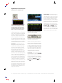
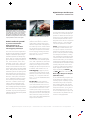
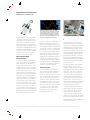
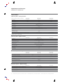
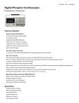
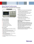
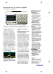
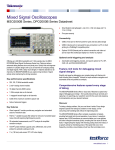
Digital Phosphor Oscilloscopes
MSO2000 Series • DPO2000 Series
Features & Benefits
Key Performance
Specifications
– 100 MHz and 200 MHz bandwidth
models
– 2 or 4 analog channels
– 16 digital channels (MSO2000 Series)
– Sample rates up to 1 GS/s on
all channels
– 1 Mega sample record length on
all channels
– 5,000 wfm/s maximum waveform
capture rate
– Suite of advanced triggers
Serial Bus Trigger and
Decode
– I2C, SPI, CAN, LIN, and RS-232/
422/485/UART serial triggering,
decode, and analysis options
Tektronix MSO2000 and DPO2000 Series Digital Phosphor Oscilloscopes
Feature-Rich Tools for Debugging Mixed Signal Designs.
The Power to Solve Problems Quickly The MSO2000 and DPO2000 Series
digital phosphor oscilloscopes (DPOs)
deliver the performance and tools you
need to visualize your signals and find
answers quickly. The DPO2000 Series
are the first oscilloscopes to provide
1 M points of usable record length on
all channels, serial trigger and decode
analysis options, a variable low-pass
filter that also allows you to see signal
details to the oscilloscope’s full bandwidth and all in a compact form factor.
The MSO2000 Series adds 16 integrated
digital channels, enabling you to visualize
and time correlate analog and digital
signals on a single instrument. This integration extends triggering functionality
across all 20 channels - which is ideal
for debugging mixed analog and
digital designs.
Digital phosphor technology enables 5,000
waveforms/second waveform capture and
real-time intensity grading on the MSO2000
and DPO2000 Series.
Designed to Make
Your Work Easier
Wave Inspector® Navigation and Search
Imagine trying to efficiently use the
Internet if search engines such as
Google and Yahoo didn’t exist and
Web browser features such as Favorites
and Links didn’t exist. Now you know
how most modern oscilloscope users
feel when trying to use the long record
length in their digital oscilloscope.
Record length, one of the key specifications of an oscilloscope, is the number
of samples it can digitize and store in
a single acquisition. The longer the
record length, the longer the time
window you can capture with high
timing resolution (high sample rate).
The first digital oscilloscopes could
capture and store only 500 points,
which made it very difficult to acquire
all relevant information around the event
being investigated. Over the years,
oscilloscope vendors have provided
longer and longer record lengths to
meet market demands for long capture
windows with high resolution. These
mega-point record lengths often
represent thousands of screens worth
of signal activity. While standard record
lengths have increased greatly over
Ease of Use Features
– Wave Inspector® Navigation and
Search provides unprecedented
efficiency in waveform analysis
– FilterVuTM variable low-pass filter
allows for removal of unwanted
signal noise while still capturing
high-frequency events
– 7 in (180 mm) bright, widescreen,
TFT-LCD color display
– USB 2.0 on front panel for quick
and easy data storage
– USB 2.0 device port on rear panel
for direct PC control of oscilloscope
using USBTMC or direct printing to
any PictBridge® compatible printer
– Plug ‘n’ Play PC connectivity
and analysis software solutions
– TekVPI® Probe Interface supports
active, differential, and current probes
for automatic scaling and units
– Small footprint and light weight only 5.3 in (134 mm) deep and 7 lb
14 oz (3.6 kg)
Mixed Signal Design and
Analysis (MSO2000 Series)
– Ability to time correlate up to 4
analog and 16 digital channels
– Parallel bus trigger and analysis
– Multichannel setup and hold triggering
– Next-generation digital waveform
display
Applications
–
–
–
–
–
–
Embedded design and debug
Mixed signal design and debug
Power measurements
Automotive electronics
Education and training
Video design and debug
Digital Phospor Oscilloscopes
MSO2000 Series • DPO2000 Series
A001_7738.tif
Search step 1: You define what you would like
to find.
Wave Inspector controls provide unprecedented
efficiency in viewing, navigating, and analyzing
waveform data. Zip through your 1 M point
record by turning the outer pan control (2).
Get from the beginning to end in seconds.
See something of interest and want to see more
details? Just turn the inner zoom control (1).
the years and can now satisfy the vast
majority of applications in the marketplace, tools for effectively and efficiently
viewing, navigating, and analyzing
long record length acquisitions have
been sorely neglected until now.
Search step 2: MSO/DPO2000 automatically
searches through the record and marks each
event with a hollow white triangle.
The Tektronix MSO/DPO2000 Series
redefines expectations for working with
long record lengths with the following
innovative Wave Inspector controls:
Search step 3: Use previous and next buttons
to jump from one event to the next.
Zoom/Pan - A dedicated, two-tier
front-panel control provides intuitive
control of both zooming and panning.
The inner control adjusts the zoom
factor (or zoom scale); turning it clockwise activates zoom and goes to
progressively higher zoom factors, while
turning it counterclockwise results in
lower zoom factors and eventually turning
zoom off. The outer control pans the
zoom box across the waveform to quickly
get to the portion of the waveform you
are interested in. The outer control also
utilizes force-feedback to determine
how fast to pan on the waveform. The
farther you turn the outer control, the
faster the zoom box moves. Pan direction
is changed by simply turning the control
the other way. No longer do you need
to navigate through multiple menus to
adjust your zoom view.
2
Search Marks - Don’t want to take
the time to inspect the entire acquisition
manually to find the event you’re looking
for? The MSO/DPO2000 Series features
a robust automatic waveform search
feature that allows you to search through
your long acquisition based on user-defined
criteria. All occurrences of the event are
highlighted with search marks and are
easily navigated to, using the front-panel
Previous
and Next
buttons.
Search types include edge, pulse width,
runt, logic, setup and hold, rise/fall time
and parallel, I2C, SPI, RS-232/422/485/
UART, CAN, and LIN packet content.
A001_7740.tif
Play/Pause - A dedicated play/pause
button on the front panel scrolls the
waveform across the display automatically
while you look for anomalies or an event
of interest. Playback speed and direction
are controlled using the intuitive pan control.
Once again, turning the control further
makes the waveform scroll faster and
changing direction is as simple as
turning the control the other way.
User Marks - See something interesting
on your waveform? Press the Set Mark
button on the front panel to leave one
or more “bookmarks” on the waveform.
Navigating between marks is as simple
as pressing the Previous
and
Next
buttons on the front panel.
Digital Phosphor Oscilloscopes • www.tektronix.com/mso2000 • www.tektronix.com/dpo2000
Digital Phospor Oscilloscopes
MSO2000 Series • DPO2000 Series
A001_7744.tif
MSO/DPO2000 triggered on a specific data
packet going across an I2C bus. No more counting
clock edges and 1s and 0s. A Bus waveform
provides decoded packet content including
Start, Address, Read/Write, Data, and Stop. And
the addition of timing waveforms makes it easy
to quickly determine values of two signals.
See the MSO/DPO2000
Series in action for yourself.
Try out the MSO/DPO2000
Virtual Oscilloscope at:
www.tektronix.com/mso2000
Serial Triggering and Analysis
One of the most common applications
requiring long record length is serial data
analysis in embedded system design.
Embedded systems are virtually everywhere. They can contain many different
types of devices including microprocessors, microcontrollers, DSPs, RAM,
EEPROMs, FPGAs, ADCs, DACs, and
I/O. These various devices have traditionally communicated with each other
and the outside world using wide parallel
buses. Today, however, more and more
embedded systems are replacing these
wide parallel buses with serial buses
due to lower board space requirements,
fewer pins, lower power, embedded
clocks, differential signaling for better
noise immunity and most importantly,
lower cost. In addition, there’s a large
supply of off-the-shelf building block
components from reputable manufacturers, enabling rapid design development.
While serial buses have a large number
of benefits, they also present significant
challenges that their predecessors (parallel
buses) did not face.
The P6316 digital probe for MSO2000 Series
simplifies connection to the device-under-test
They make debugging bus and system
problems more difficult, it’s harder to
isolate events of interest and it’s more
difficult to interpret what is displayed on
the oscilloscope screen. The MSO2000
and DPO2000 Series address these
challenges and represent the ultimate
tool for engineers working with serial
buses such as I2C, SPI, RS-232/422/
485/UART, CAN, and LIN.
Bus Display - Provides a higher level,
combined view of the individual signals
(clock, data, chip enable, etc.) that make
up your bus, making it easy to identify
where packets begin and end and
identifying sub-packet components such
as address, data, identifier, CRC, etc.
Serial Triggering - Trigger on packet
content such as start of packet, specific
addresses, specific data content, unique
identifiers, etc., on popular serial interfaces - I2C, SPI, RS-232/422/485/UART,
CAN, and LIN.
Bus Decoding - Tired of having to
visually inspect the waveform to count
clocks and determine if each bit is a 1
or a 0, and then combine bits into bytes
and determine the hex value? Let the
oscilloscope do it for you! Once you’ve
set up a bus, the oscilloscope will decode
each packet on the bus and display the
value in either hex, binary, decimal (LIN
only), or ASCII (RS-232/422/485/UART
only) in the bus waveform.
Event Table - In addition to seeing
decoded packet data on the bus waveform itself, you can view all captured
packets in a tabular view much like you
would see on a logic analyzer. Packets
are time-stamped and listed consecutively with columns for each component
(Address, Data, etc.). The event table
can also be exported for use offline.
Search - Serial triggering is very useful
for isolating an event of interest, but
once you’ve captured it and need to
analyze the surrounding data, what do
you do? In the past, you had to manually
scroll through the waveform, counting
and converting bits and looking for what
caused the event. With the MSO2000
and DPO2000 Series, you can have the
oscilloscope automatically search through
the acquired data for user-defined criteria
including serial packet content. Each
occurrence is marked for easy reference.
Rapid navigation between marks is as
simple as pressing the Previous
and Next
buttons on the front panel.
Mixed Signal Design and Analysis
(MSO2000 Series)
As an embedded-design engineer, you
are faced with the challenge of everincreasing system complexity. A typical
embedded design may incorporate
various analog signals, high- and lowspeed serial digital communication and
microprocessor buses, just to name a
few. Serial protocols such as I2C and
SPI are used frequently for chip-to-chip
communication, but parallel buses are
still used in many applications.
Digital Phosphor Oscilloscopes • www.tektronix.com/mso2000 • www.tektronix.com/dpo2000
3
Digital Phospor Oscilloscopes
MSO2000 Series • DPO2000 Series
A001_7749.tif
Microprocessors, FPGAs, Analog-toDigital Converters (ADCs), and Digitalto-Analog Converters (DACs) are all
examples of ICs that present unique
measurement challenges in today’s
embedded designs. The MSO2000
Series Mixed Signal Oscilloscopes offer
the addition of 16 digital channels. These
channels are tightly integrated into the
oscilloscope’s user interface, simplifying
operation and making it possible to
solve mixed signal issues easily.
Next Generation Digital
Waveform Display
In a continued effort to make mixed
signal oscilloscopes easy to use, the
MSO2000 Series has redefined the
way you view digital waveforms. One
common problem shared by both logic
analyzers and mixed signal oscilloscopes
is determining if data is a one or a zero
when zoomed in far enough that the
digital trace stays flat all the way across
the display. The MSO2000 has colorcoded the digital traces, displaying ones
in green and zeros in blue. In addition,
the MSO2000 displays white edges
around the transition points of digital
channels when there is uncertainty
between sample points. This acts as
a visual reminder that increasing the
sample rate on the next acquisition will
reveal higher frequency information than
your previous settings could acquire.
Output of DAC Signal) Notice how FilterVuTM
clearly shows the noise-free steps of the DAC
in the foreground trace (yellow) which has
removed all frequencies above 5.5 kHz. FilterVu
also captures and displays high-frequency
glitches up to the full bandwidth of the oscilloscope in the background trace (orange).
Channel setup on an MSO can often
be time consuming as compared to the
traditional oscilloscope. This process
often includes probing the device undertest, labeling the channels, and positioning
the channels on screen. The MSO2000
simplifies this process by allowing the
user to group digital waveforms and
enter waveform labels using a USB
keyboard. By simply placing digital
waveforms next to each other, they form
a group. Once a group is formed, you
can position all the channels contained
in that group together. This greatly reduces
the normal setup time associated with
positioning channels individually.
P6316 MSO Probe
This unique probe design offers two
eight-channel pods and simplifies the
process of connecting to the deviceunder-test. When connecting to square
pins, the P6316 can connect directly to
8x2 square pin headers spaced on
tenth-inch centers. When more attachment flexibility is required, you can use
the included flying lead sets and grabbers to clip onto surface mount devices
or test points. The P6316 offers
outstanding electrical characteristics
applying only 8 pF of loading with
101 kΩ input impedance.
Easily capture, save and analyze measurement results.
FilterVuTM Variable Low-Pass Filter
Tired of being limited to a 20 MHz
bandwidth filter in your oscilloscope?
Simply turn on FilterVu and adjust the
variable low-pass noise filter. Unlike
other variable low-pass filters, FilterVu
filters out the unwanted noise from your
signal while still capturing glitches and
other signal details up to the full bandwidth of the oscilloscope. It does this
by showing two waveforms: a waveform
that can be filtered (foreground waveform)
and a glitch capture waveform (background waveform).
The filtered waveform uses a variable
low-pass filter to block out noise,
yielding a cleaner waveform to more
precisely locate signal edges and amplitude levels. The result is improved
confidence in you cursor measurements and cleaner documentation of
important signal attributes. When the
noise filter is adjusted to the lowest
available noise cutoff frequency, no
more than 1% of high-frequency content
that could cause the oscilloscope to
alias will pass through the filter.
The glitch capture waveform shows
signal details up to the full bandwidth
of the oscilloscope. The oscilloscope
captures pulses as narrow as 5 ns,
using peak detect min/max sampling,
protecting you from missing unexpected
glitches or other high-frequency events.
FilterVu is ideal for repetitive, nonrepetitive
and single-shot events.
4
Digital Phosphor Oscilloscopes • www.tektronix.com/mso2000 • www.tektronix.com/dpo2000
Digital Phospor Oscilloscopes
MSO2000 Series • DPO2000 Series
A001_7750.tif
OpenChoice® Desktop - Standard software
seamlessly connects the oscilloscope to a PC.
PC Connectivity and
USB Data Storage
The MSO2000 and DPO2000 Series
provides flexibility in data transfer with
standard USB host and device ports
which enable removable data storage,
seamless PC connectivity, and direct
printing. Also available are optional
GPIB, LAN, and Video-Out adaptors.
Easily capture, save and analyze
measurement results with OpenChoice®
Desktop PC Communications software.
Simply pull screen images and waveform data into the stand-alone desktop
application or directly in Microsoft Word
and Excel. To complement OpenChoice,
National Instruments LabVIEW
SignalExpressTM Tektronix Edition
software provides you with extended
capabilities, including advanced analysis,
remote oscilloscope control and live
waveform analysis. Alternatively, if you
prefer not to use the PC, you can simply
print your image directly to any
PictBridge® compatible printer using
the USB device port.
A001_7751.tif
NI LabVIEW SignalExpressTM Tektronix Edition Fully interactive measurement acquisition
and analysis software developed jointly with
National Instruments, and optimized for the
MSO/DPO2000 Series.
A001_7752.tif
e*Scope enables control of your network
connected oscilloscope from any network
connected PC through a traditional
browser interface.
TekVPI® Probing
The TekVPI probe interface sets the
standard for ease of use in probing.
TekVPI probes feature status indicators
and controls, as well as a probe menu
button right on the input compensation
box itself. This button brings up a probe
menu on the oscilloscope display with
all relevant settings and controls for the
probe. The TekVPI interface utilizes a
new probe power management architecture enabling direct attachment of
current probes (Requires TekVPI
External Power Supply - Tektronix Part
number: 119-7465-xx). Finally, TekVPI
probes can be controlled remotely
by using USB, GPIB, or Ethernet,
enabling more versatile solutions in
ATE environments.
Digital Phosphor Oscilloscopes • www.tektronix.com/mso2000 • www.tektronix.com/dpo2000
5
Digital Phospor Oscilloscopes
Digital Phospor Oscilloscopes
MSO2000 Series • DPO2000 Series
MSO2000 Series • DPO2000 Series
8
3
1 Zoom/Pan – Dedicated front panel controls for
zooming and panning. Get from the start to the end
of your 1 M record in seconds. The inner control
adjusts the zoom factor while the outer ring adjust
pans the zoom box across the waveform. Navigating
your waveform has never been easier.
9
1
2 Marks – Want to mark your waveform for future
reference or for quick navigation between events of
interest? Simply press the Set Mark button to place
“bookmarks” on your waveform. Use the Next and
previous buttons to navigate through user marks
and search generated marks.
3 Search – Tired of turning the horizontal position
control endlessly on your current scope to find the
event you’re looking for? Use the MSO/DPO2000’s
powerful Search feature to automatically find and
mark all occurrences of an event based on user
specified criteria. Search types include edge, pulse
width, runt, logic, multichannel setup and hold,
rise/fall time and I2C, SPI, CAN, LIN, and RS232/422/485/UART packet content.
2
7
A001_7743.tif
6
4 2 or 4 Analog Channels and 16 Digital
Channels – View and trigger on up to 20 time
correlated signals on the same display. (16 Digital
Channels on MSO models only.)
5 Parallel and Serial Buses – Trigger on parallel
or serial packet level content, view acquired data as a
bus with all data decoded into hex, binary or ASCII,
search through acquisitions for specific content and
even view all decoded data in a tabular format, much
like you would see on a logic analyzer. Standards
supported include I2C, SPI, CAN, LIN, and RS-232/
422/485/UART. Analyze up to two buses at the same
time. (Parallel is available on MSO models only.)
6 Dedicated Vertical Controls – Vertical
controls provide simple and intuitive operation.
No longer do you need to share one set of
vertical controls across all four channels.
6
11
10
7 Large Widescreen, Digital Phosphor
Display – The MSO/DPO2000 Series boasts
a bright, 7 inch (180 mm), widescreen display.
Discover and troubleshoot design problems faster
with 5,000 waveforms/second continuous waveform capture rate and real time intensity grading.
Continuous high waveform capture rate saves time
by quickly revealing the nature of faults so advanced
triggers can be applied to isolate them. Real time
intensity grading exposes the “history” of a signal’s
activity as they accumulate. The digital phosphor
display makes its easier to understand the characteristics of the transients you have captured. It
intensifies the areas where the signal trace
occurs more frequently.
4
8 FilterVu™ Variable Low-Pass Filter –
Tired of dealing with unwanted noise on your
signal? Ever wished your oscilloscope had bandwidth limiters below 20 MHz? Simply turn on
FilterVu and adjust the variable low-pass noise
filter. Unlike other variable low pass filters,
FilterVu filters out the unwanted noise from your
signal while still capturing glitches and other
signal details up to the full bandwidth of the
oscilloscope. FilterVu is ideal for repetitive,
single-shot and non-repetitive events.
Digital Phosphor Oscilloscopes • www.tektronix.com/mso2000 • www.tektronix.com/dpo2000
5
9 Serial Trigger and Decode Application
Module – MSO/DPO2000 Series have 2 slots for
application modules. Application specific modules
extend how you use your oscilloscope by adding
serial bus triggering and decode. DPO2AUTO –
Automotive serial bus triggering and decode with
support for CAN and LIN buses. DPO2COMPComputer bus serial triggering and decode with
support for RS-232/422/485/UART buses.
DPO2EMBD – Embedded bus serial triggering
and decode with support for I2C and SPI buses.
10 USB – Use the front-panel USB host port for
simple and convenient storage of screenshots,
waveform data, and oscilloscope setups. Use the
rear-panel USB device port to easily communicate and control your oscilloscope from a PC.
Or use the rear-panel USB device port to directly
print your screen image to any PictBridge®
compatible printer.
Only 5.3 in. Deep! – Despite the impressive
performance, huge display, and knob-per-channel
controls, the DPO4000 Series is only 5.4 in. deep,
saving you valuable space on your test bench.
11 TekVPI® – TekVPI probe interface provides for
direct-connect current probes, intuitive comp box
controls, remote control of probe settings and
smarter communication between the oscilloscope
and the probe.
Digital Phosphor Oscilloscopes • www.tektronix.com/mso2000 • www.tektronix.com/dpo2000
7
Digital Phospor Oscilloscopes
MSO2000 Series • DPO2000 Series
Characteristics
Vertical System - Analog Channels
Vertical System Analog Channels
MSO2012
DPO2012
Input Channels
2
Analog Bandwidth*1 (-3 dB)
100 MHz
Calculated Rise Time
3.5 ns
Hardware Bandwidth Limits
Input Coupling
Input Impedance
Input Sensitivity Range
Vertical Resolution
Max Input Voltage
DC Gain Accuracy (with offset set to 0 V)
Offset Range
2 mV/div to 200 mV/div
>200 mV/div to 5 V/div
Channel-to-Channel Isolation(Any Two Channels at Equal Vertical Scale)
MSO2014
DPO2014
MSO2024
DPO2024
4
100 MHz
3.5 ns
20 MHz
AC, DC, GND
1 MΩ ±2%, 11.5 pF ±2 pF
2 mV/div to 5 V/div
8 bits
300 VRMS with peaks ≤450 V
±3% for 10 mV/div to 5 V/div, ±4% for 2 mV/div to 5 mV/div
4
200 MHz
2.1 ns
±1 V
±25 V
≥100:1 at ≤100 MHz
≥100:1 at ≤200 MHz
MSO2014
MSO2024
*1 Bandwidth is 20 MHz at 2 mV/div, all models
Vertical System - Digital Channels
MSO2012
Input Channels
Thresholds
Threshold Selections
User Defined Threshold Range
Maximum Input Voltage
Threshold Accuracy
Maximum Input Dynamic Range
Minimum Voltage Swing
Input Impedance
Probe Loading
Vertical Resolution
16 Digital (D15 to D0)
Threshold per set of 8 channels
TTL, CMOS, ECL, PECL, User Defined
±20 V
±40 V
±(100 mV + 3% of threshold setting)
80 Vpk-pk (threshold setting dependent)
500 mV Peak-to-Peak
101 kΩ
8 pF
1 bit
Horizontal System - Analog Channels
MSO2012
DPO2012
Maximum Sample Rate (all channels)
Minimum Peak Detect Pulse Width
Maximum Record Length (all channels)
Maximum Duration of Time Captured at Highest Sample Rate (all channels)
Timebase Range
Timebase Delay Time Range
Channel-to-Channel Deskew Range
Timebase Accuracy
MSO2014
DPO2014
MSO2024
DPO2024
1 GS/s
7.0 ns
3.5 ns
1 M points
1 ms
4 ns to 100 s
2 ns to 100 s
-10 div to 5000 s
±100 ns
±25 ppm
Horizontal System - Digital Channels
MSO2012
Maximum Sample Rate (when using any of channels D7-D0)
Maximum Sample Rate (when using any of channels D15-D8)
Maximum Record Length
Minimum Detectable Pulse Width
Channel-to-Channel Skew
8
MSO2014
MSO2024
1 GS/s (1 ns resolution)
500 MS/s (2 ns resolution)
1 M points
5 ns
2 ns typical
Digital Phosphor Oscilloscopes • www.tektronix.com/mso2000 • www.tektronix.com/dpo2000
Digital Phospor Oscilloscopes
MSO2000 Series • DPO2000 Series
Acquisition Modes
Trigger Modes
Waveform Measurements
Sample – Acquires sampled values.
Peak Detect – Captures glitches as narrow as
3.5 ns at all sweep speeds.
Averaging – From 2 to 512 waveforms included
in average.
Roll – Scrolls waveforms right to left across screen
at sweep speeds slower than or equal to 40 ms/div.
Edge – Positive or negative slope on any channel or
front-panel auxiliary input. Coupling includes DC, HF
reject, LF reject, and noise reject.
Pulse Width – Trigger on width of positive or negative
pulses that are >, <, =, or ≠ to a specified period
of time.
Runt – Trigger on a pulse that crosses one
threshold but fails to cross a second threshold
before crossing the first again.
Logic – Trigger when any logical pattern of channels
goes false or stays true for specified period of time.
Any input can be used as a clock to look for the pattern
on a clock edge. Pattern (AND, NAND) specified for
all analog and digital input channels defined as High,
Low, or Don’t Care.
Setup and Hold – Trigger on violations of both
setup time and hold time between clock and data
present on any of the input channels.
Rise/Fall Time – Trigger on pulse edge rates that
are faster or slower than specified. Slope may be
positive, negative, or either.
Video – Trigger on line number, all lines, odd, even,
or all fields on NTSC, PAL and SECAM video signals.
I2C (Optional) – Trigger on Start, Repeated Start,
Stop, Missing ACK, Address (7 or 10 bit), Data, or
Address and Data on I2C buses up to 3.4 Mb/s.
SPI (Optional) – Trigger on SS, Idle Time, MOSI,
MISO, or MOSI and MISO on SPI buses up to
10.0 Mb/s.
CAN (Optional) – Trigger on Start of Frame, Frame
Type (data, remote, error, overload), Identifier (standard or extended), Data, Identifier and Data, End of
Frame, Missing ACK, or Bit Stuffing Errors on CAN
signals up to 1 Mb/s. Data can be further specified
to trigger on ≤, <, =, >, ≥ or ≠ a specific data value.
User-adjustable sample point is set to 50% by default.
RS-232/422/485/UART (Optional) – Trigger on
Tx start bit, Rx start bit, Tx end of packet, Rx end
of packet, Tx data, Rx data, Tx Parity Error, and Rx
Parity Error.
LIN (Optional) – Trigger on Sync, Identifier, Data,
Identifier and Data, Wakeup Frame, Sleep Frame,
or Errors such as Sync Parity or Checksum Errors.
Parallel (available on MSO models only) – Trigger
on a parallel bus data value.
Cursors – Waveform and Screen
Automatic Measurements – 29, of which up to
four can be displayed on screen at any one time.
Measurements include Frequency, Period, Delay,
Rise Time, Fall Time, Positive Duty Cycle, Negative
Duty Cycle, Positive Pulse Width, Negative Pulse
Width, Burst Width, Phase, Positive Overshoot,
Negative Overshoot, Peak-to-Peak, Amplitude, High,
Low, Max, Min, Mean, Cycle Mean, RMS, Cycle
RMS, Positive Pulse Count, Negative Pulse Count,
Rising Edge Count, Falling Edge Count, Area and
Cycle Area.
Gating – Isolate the specific occurrence within an
acquisition to take measurements, using either the
screen or waveform cursors.
Trigger System
Main Trigger Modes – Auto, Normal and Single.
Trigger Coupling – DC, HF reject (attenuates
>85 kHz), LF reject (attenuates <65 kHz), noise
reject (reduces sensitivity).
Trigger Holdoff Range – 20 ns to 8 s.
Trigger Signal Frequency Counter – Provides a
higher accuracy means of identifying the frequency
of trigger signals. Trigger Signal Frequency counter
resolution is 6 digits.
Trigger Level Range
Any Channel – ±4.92 divisions from center
of screen.
External (auxiliary input) – ±6.25V, 1x attenuation;
±12.5V, 10x attenuation.
Sensitivity
Internal DC Coupled
Trigger Source
Analog Inputs
Sensitivity
0.4 division from DC to 50 MHz
0.6 divisions >50 MHz to 100 MHz
0.8 divisions >100 MHz to 200 MHz
External (Auxiliary Input)200 mV from DC to 100 MHz,
1x attenuation
Waveform Math
Arithmetic – Add, subtract, and multiply waveforms.
Software
NI LabVIEW SignalExpressTM Tektronix Edition LE –
A fully interactive measurement software environment optimized for the MSO2000/DPO2000 Series,
enables you to instantly acquire, generate, analyze,
compare, import, and save measurement data and
signals using an intuitive drag-and-drop user interface that does not require any programming. Standard
MSO2000/DPO2000 Series support for acquiring,
controlling, viewing and exporting your live signal
data is permanently available through the software.
The full version (SIGEXPTE) adds additional signal
processing, advanced analysis, mixed signal,
sweeping, limit testing, and user-defined step capabilities and is available for a 30-day trial period standard with each instrument.
OpenChoice® Desktop – Enables fast and easy
communication between a Windows PC and the
MSO2000/DPO2000 Series, using USB or LAN.
Transfer and save settings, waveforms, measurements and screen images.
IVI Driver – Provides a standard instrument
programming interface for common applications
such as LabVIEW, LabWindows/CVI, Microsoft
.NET and MATLAB.
Digital Phosphor Oscilloscopes • www.tektronix.com/mso2000 • www.tektronix.com/dpo2000
9
Digital Phospor Oscilloscopes
MSO2000 Series • DPO2000 Series
Display Characteristics
Display Type – 7 in (180 mm) liquid crystal TFT
color display.
Display Resolution – 480 horizontal x 234 vertical
pixels (WQVGA).
Waveform Styles – Vectors, Dots (In Video Trigger
mode), Variable Persistence, Infinite Persistence.
Graticules – Full, Grid, Cross Hair, Frame.
Format – YT and XY.
Waveform Capture Rate – Up to 5,000 wfms/sec.
Input/Output Ports
USB 2.0 High-Speed Host Port – Supports USB
data storage devices and keyboards.
USB 2.0 High-Speed Device Port – Rear-panel
port supports communication/control of oscilloscope
by PC and all PictBridge® compatible printers.
LAN Port – RJ-45 connector, supports 10/100Base-T
(requires DPO2CONN).
GPIB – Adapt USB 2.0 device port to a GPIB port
(requires TEK-USB-488).
Video Out Port – DB-15 female connector, connect
to show the oscilloscope display on an external
monitor or projector (requires DPO2CONN).
Auxiliary Input – Front-panel BNC connector. Input
Impedance 1 MΩ ±2%. Max input 300 VRMS with
peaks ±450 V.
Probe Compensator Output – Front-panel pins,
Amplitude 5.0 V, Frequency 1 kHz.
Kensington Lock – Rear-panel security slot
connects to standard Kensington style lock.
PowerSource
Power Source Voltage – 100 to 240 V ±10%.
PowerSource Frequency – 45 to 65 Hz
(90 to 264 V), 360 to 440 Hz (100 to 132 V).
Power Consumption – 80 W maximum.
TekVPI External Power Supply (119-7465-xx) –
Output voltage: 12 V; Output current: 4.2 A; Power
consumption: 50 W.
10
Regulatory
Physical Characteristics
Dimensions
Height
Width
Depth
Weight
Net
Shipping
mm
180
377
134
kg
3.6
6.2
in
7.1
14.9
5.3
lb
7.9
13.7
Electromagnetic Compatibility – 2004/108/EC.
Safety – Listed UL61010-1: 2004, CAN/CSA-C22.2
No. 61010.1: 2004; Complies with EN61010-1:
2001, Complies with the Low Voltage Directive
2004/108/EC for Product Safety.
MSO2000 Models
Rackmount Configuration - 4 U
Cooling Clearance - 50 mm (2 inches) on the left
side and rear (when looking at the front of the
instrument).
MSO2012– 100 MHz, 1 GS/s, 1 M record length,
2+16 channel mixed signal oscilloscope.
MSO2014– 100 MHz, 1 GS/s, 1 M record length,
4+16 channel mixed signal oscilloscope.
MSO2024– 200 MHz, 1 GS/s, 1 M record length,
4+16 channel mixed signal oscilloscope.
General Characteristics
DPO2000 Models
Environmental
Temperature
Operating – 0 ºC to +50 ºC.
Nonoperating – -40 ºC to +71 ºC.
Humidity
Operating – High: 30 ºC to 50 ºC, 5% to 60%
Relative Humidity. Low: 0 ºC to 30 ºC, 5% to 95%
Relative Humidity.
Nonoperating – High: 30 ºC to 55 ºC, 5% to 60%
Relative Humidity. Low: 0 ºC to 30 ºC, 5% to 95%
Relative Humidity.
Altitude
Operating – 3,000 meters (9,843 feet).
Nonoperating – 12,000 meters (39,370 feet).
Random Vibration
DPO2012– 100 MHz, 1 GS/s, 1 M record length,
2-channel digital phosphor oscilloscope.
DPO2014– 100 MHz, 1 GS/s, 1 M record length,
4-channel digital phosphor oscilloscope.
DPO2024– 200 MHz, 1 GS/s, 1 M record length,
4-channel digital phosphor oscilloscope.
All models include:One P2221 200 MHz, 1x/10x
Passive Probe per Analog Channel, User Manual
and Translated Front-Panel Overlay, Documentation
CD (063-4118-xx), OpenChoice® Desktop Software,
NI LabVIEW SignalExpressTM Tektronix Edition LE
Software, Calibration certificates document measurement traceability to National Metrology Institute(s)
and ISO9001Quality System Registration, Power
Cord, and a three-year warranty. MSO models also
include one P6316 16-channel logic probe and
accessory kit, and accessory bag (016-2008-xx).
Please specify power plug and manual version
when ordering.
Operating – 0.31 GRMS from 5 to 500 Hz,
10 minutes each axis, 3 axes, 30 minutes total.
Nonoperating – 2.46 GRMS from 5 to 500 Hz,
10 minutes each axis, 3 axes, 30 minutes total.
Digital Phosphor Oscilloscopes • www.tektronix.com/mso2000 • www.tektronix.com/dpo2000
Digital Phospor Oscilloscopes
MSO2000 Series • DPO2000 Series
Recommended Serial Bus
Application Modules
DPO2EMBD– Embedded Serial Triggering and
Analysis Module. Enables triggering on packet level
information on I2C and SPI buses as well as analytical tools such as bus views, packet decoding,
search tools, and packet decode tables with timestamp information.
DPO2COMP– Computer Serial Triggering and
Analysis Module. Enables triggering on packet level
information on RS-232/422/485/UART buses as
well as analytical tools such as bus views, packet
decoding, search tools, and packet decode tables
with timestamp information.
DPO2AUTO– Automotive Serial Triggering and
Analysis Module. Enables triggering on packet
level information on CAN and LIN buses as well
as analytical tools such as bus views, packet
decoding, search tools, and packet decode tables
with timestamp information.
Options
International Power Plugs
Opt. A0– North America power.
Opt. A1– Universal EURO power.
Opt. A2– United Kingdom power.
Opt. A3– Australia power.
Opt. A5– Switzerland power.
Opt. A6– Japan power.
Opt. A10– China power.
Opt. A11– India power.
Opt. A99– No power cord or AC adapter.
Language Options*1
Opt. L0– English manual.
Opt. L1– French manual.
Opt. L2– Italian manual.
Opt. L3– German manual.
Opt. L4– Spanish manual.
Opt. L5– Japanese manual.
Opt. L6– Portuguese manual.
Opt. L7– Simplified Chinese manual.
Opt. L8– Standard Chinese manual.
Opt. L9– Korean manual.
Opt. L10– Russian manual.
Opt. L99– No manual.
Service Options*2
Opt. C3– Calibration Service 3 years.
Opt. C5– Calibration Service 5 years.
Opt. CA1– Provides a single calibration event,
or coverage for the designated calibration interval,
whichever comes first.
Opt. D1– Calibration Data Report.
Opt. D3– Calibration Data Report 3 years
(with Opt. C3).
Opt. D5– Calibration Data Report 5 Years
(with Opt. C5).
Opt. R5– Repair Service 5 years
(including warranty).
Soft carrying case with front protective cover for
MSO2000 and DPO2000 Series (ACD2000).
Recommended Probes
Recommended Accessories
TAP1500*3– 1.5 GHz TekVPI™ single-ended
active probe.
TDP0500*3, *5– 500 MHz TekVPI™ 42 V
differential probe.
TCP0030*3– 120 MHz TekVPI™ 30 Ampere
AC/DC current probe.
TCP0150*3– 20 MHz TekVPI™ 150 Ampere
AC/DC current probe.
TCPA300/400*6– Current measurement
system amplifiers.
TCP305– DC to 50 MHz, 50 A current probe
for use with TCPA300.
TCP404XL– DC to 2 MHz, 500 A current probe
for use with TCPA400.
P5100– 2.5 kV, 100X high-voltage passive probe.
P5200– 1.3 kV, 50X/500X, 25 MHz high-voltage
active differential probe.
P5205*3, *4– 1.3 kV, 100 MHz high-voltage
differential probe.
P5210*3, *4– 5.6 kV, 50 MHz high-voltage
differential probe.
ADA400A*3, *4– 100x, 10x, 1x, 0.1x high-gain
differential amplifier.
DPO2CONN – Adds Ethernet (10/100Base-T) and
Video Out Port.
Service manual – Order 071-2331-xx (English only).
TPA-BNC*3 – TekVPI to TekProbe BNC Adapter.
TekVPI External Power Supply – Order 119-7465-xx.
TEK-USB-488 – GPIB to USB Adapter.
Digital Probe Leadset (8 Channels) – Order 1963508-xx.
TEK-DPG*3 – TekVPI Deskew Pulse Generator
Signal Source.
Deskew and Calibration Fixture – Order 0671686-xx.
Rackmount Kit – Order RMD2000. Does not
include slide-out rails.
Soft Transit Case and Front Protective Cover
– Order ACD2000.
Front Protective Cover – Order 200-5045-xx.
Hard Transit Case – Order HCTEK4321 (Requires
ACD2000).
SIGEXPTE – NI LabVIEW SignalExpressTM Tektronix
Edition Software (Full Version).
USB Keyboard – Order 119-7083-00.
A001_7753.tif
Warranty
Three-year warranty covering all parts and labor,
excluding probes.
*1 Language options include translated front-panel overlay
for the selected language(s).
*2 Probes and accessories are not covered by the oscilloscope
warranty and Service Offerings.
Refer to the datasheet of each probe and accessory model
for its unique warranty and calibration terms.
*3 Requires TekVPI external power adapter (119-7465-00);
one per oscilloscope.
*4 Requires TPA-BNC adapter.
*5 Probes terminate into 50 Ω but oscilloscope will automatically
adjust to account for 1 MΩ input.
*6 Requires 50 Ω feed through termination between the
oscilloscope input and the BNC cable.
Digital Phosphor Oscilloscopes • www.tektronix.com/mso2000 • www.tektronix.com/dpo2000
11
Digital Phospor Oscilloscopes
MSO2000 Series • DPO2000 Series
Contact Tektronix:
ASEAN / Australasia (65) 6356 3900
Austria +41 52 675 3777
Balkans, Israel, South Africa and other ISE Countries +41 52 675 3777
Belgium 07 81 60166
Brazil & South America (11) 40669400
Canada 1 (800) 661-5625
Central East Europe, Ukraine and the Baltics +41 52 675 3777
Central Europe & Greece +41 52 675 3777
Denmark +45 80 88 1401
Finland +41 52 675 3777
France +33 (0) 1 69 86 81 81
Germany +49 (221) 94 77 400
Hong Kong (852) 2585-6688
India (91) 80-22275577
Italy +39 (02) 25086 1
Japan 81 (3) 6714-3010
Luxembourg +44 (0) 1344 392400
Mexico, Central America & Caribbean 52 (55) 5424700
Middle East, Asia and North Africa +41 52 675 3777
The Netherlands 090 02 021797
Norway 800 16098
People’s Republic of China 86 (10) 6235 1230
Poland +41 52 675 3777
Portugal 80 08 12370
Republic of Korea 82 (2) 6917-5000
Russia & CIS +7 (495) 7484900
South Africa +27 11 206 8360
Spain (+34) 901 988 054
Sweden 020 08 80371
Switzerland +41 52 675 3777
Taiwan 886 (2) 2722-9622
United Kingdom & Eire +44 (0) 1344 392400
USA 1 (800) 426-2200
For other areas contact Tektronix, Inc. at: 1 (503) 627-7111
Updated 12 November 2007
For Further Information
Tektronix maintains a comprehensive, constantly expanding collection of
application notes, technical briefs and other resources to help engineers
working on the cutting edge of technology. Please visit www.tektronix.com
Product(s) are manufactured in ISO registered facilities.
Product(s) complies with IEEE Standard 488.1-1987, RS-232-C, and with
Tektronix Standard Codes and Formats.
Copyright © 2008, Tektronix. All rights reserved. Tektronix products are
covered by U.S. and foreign patents, issued and pending. Information
in this publication supersedes that in all previously published material.
Specification and price change privileges reserved. TEKTRONIX and
TEK are registered trademarks of Tektronix, Inc. All other trade names
referenced are the service marks, trademarks or registered trademarks
of their respective companies.
10/08 WOW
3GW-22048-0