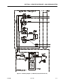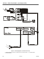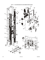
1
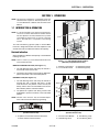
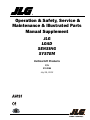
Operation & Safety, Service &
Maintenance & Illustrated Parts
Manual Supplement
JLG
LOAD
SENSING
SYSTEM
Vertical Lift Products
P/N
3124289
July 29, 2013
INTRODUCTION
INTRODUCTION - MAINTENANCE SAFETY PRECAUTIONS
GENERAL
MAINTENANCE
This section contains the general safety precautions
which must be observed during maintenance of the aerial
platform. It is of utmost importance that maintenance personnel pay strict attention to these warnings and precautions to avoid possible injury to themselves or others, or
damage to the equipment. A maintenance program must
be followed to ensure that the machine is safe to operate.
MODIFICATION OF THE MACHINE WITHOUT CERTIFICATION BY
A RESPONSIBLE AUTHORITY THAT THE MACHINE IS AT LEAST
AS SAFE AS ORIGINALLY MANUFACTURED, IS A SAFETY VIOLATION.
The specific precautions to be observed during maintenance are inserted at the appropriate point in the manual.
These precautions are, for the most part, those that apply
when servicing hydraulic and larger machine component
parts.
Your safety, and that of others, is the first consideration
when engaging in the maintenance of equipment. Always
be conscious of weight. Never attempt to move heavy
parts without the aid of a mechanical device. Do not allow
heavy objects to rest in an unstable position. When raising
a portion of the equipment, ensure that adequate support
is provided.
SINCE THE MACHINE MANUFACTURER HAS NO DIRECT CONTROL OVER THE FIELD INSPECTION AND MAINTENANCE,
SAFETY IN THIS AREA IS THE RESPONSIBILITY OF THE OWNER/
OPERATOR.
FAILURE TO COMPLY WITH SAFETY PRECAUTIONS LISTED IN
THIS SECTION MAY RESULT IN MACHINE DAMAGE, PERSONNEL
INJURY OR DEATH AND IS A SAFETY VIOLATION.
• REMOVE ALL RINGS, WATCHES AND JEWELRY
WHEN PERFORMING ANY MAINTENANCE.
• DO NOT WEAR LONG HAIR UNRESTRAINED, OR
LOOSE-FITTING CLOTHING AND NECKTIES WHICH
ARE APT TO BECOME CAUGHT ON OR ENTANGLED
IN EQUIPMENT.
• OBSERVE AND OBEY ALL WARNINGS AND CAUTIONS ON MACHINE AND IN SERVICE MANUAL.
• KEEP OIL, GREASE, WATER, ETC. WIPED FROM
STANDING SURFACES AND HAND HOLDS.
• NEVER WORK UNDER AN ELEVATED PLATFORM
UNTIL PLATFORM HAS BEEN SAFELY RESTRAINED
FROM ANY MOVEMENT BY BLOCKING OR OVERHEAD SLING.
• BEFORE MAKING ADJUSTMENTS, LUBRICATING OR
PERFORMING ANY OTHER MAINTENANCE, SHUT
OFF ALL POWER CONTROLS.
• BATTERY SHOULD ALWAYS BE DISCONNECTEDDURING REPLACEMENT OF ELECTRICAL COMPONENTS.
• KEEP ALL SUPPORT EQUIPMENT AND ATTACHMENTS STOWED IN THEIR PROPER PLACE.
• USE ONLY APPROVED, NONFLAMMABLE CLEANING
SOLVENTS.
HYDRAULIC SYSTEM SAFETY
It should be noted that the machines hydraulic systems
operate at extremely high, potentially dangerous pressures. Every effort should be made to relieve any system
pressure prior to disconnecting or removing any portion of
the system.
3124289
– JLG Lift –
A
INTRODUCTION
REVISION LOG
July 1, 2003 - Original issue of Manual
March 1, 2004 - Revised
May 17, 2005 - Revised
July 15, 2006 - Revised
March 31, 2011 - Revised
March 1, 2012 - Revised
August 11, 2012 - Revised
January 23, 2013 - Revised
July 29, 2013 - Revised
B
– JLG Lift –
3124289
TABLE OF CONTENTS
TABLE OF CONTENTS
SUBJECT - SECTION, PARAGRAPH
SECTION
PAGE NO.
- INTRODUCTION - MAINTENANCE SAFETY PRECAUTIONS
GENERAL . . . . . . . . . . . . . . . . . . . . . . . . . . . . . . . . . . . . . . . . . . . . . . . . . . . . . . . . . . . . . . . . . . . . . . A
HYDRAULIC SYSTEM SAFETY . . . . . . . . . . . . . . . . . . . . . . . . . . . . . . . . . . . . . . . . . . . . . . . . . . . . . A
MAINTENANCE . . . . . . . . . . . . . . . . . . . . . . . . . . . . . . . . . . . . . . . . . . . . . . . . . . . . . . . . . . . . . . . . . A
EFFECTIVITY . . . . . . . . . . . . . . . . . . . . . . . . . . . . . . . . . . . . . . . . . . . . . . . . . . . . . . . . . . . . . . . . . . . B
SECTION 1 - OPERATION
1.1 INTRODUCTION & OPERATION . . . . . . . . . . . . . . . . . . . . . . . . . . . . . . . . . . . . . . . . . . . . . . . . . . . 1-1
Overload Indication . . . . . . . . . . . . . . . . . . . . . . . . . . . . . . . . . . . . . . . . . . . . . . . . . . . . . . . . . 1-1
Overload Recovery . . . . . . . . . . . . . . . . . . . . . . . . . . . . . . . . . . . . . . . . . . . . . . . . . . . . . . . . . 1-2
SECTION 2 - SERVICE PROCEDURES - LOAD SENSING SYSTEM
2.1 LOAD SENSING SYSTEM (LSS) DESCRIPTION. . . . . . . . . . . . . . . . . . . . . . . . . . . . . . . . . . . . . . . 2-1
Manually Propelled Vertical Lift - Overload Detection (Manually Propelled Lifts). . . . . . . . . . 2-1
Drivable Vertical Lift - Overload Detection (Drivable Vertical Lifts) . . . . . . . . . . . . . . . . . . . . . 2-1
2.2 LSS - SETUP AND ADJUSTMENT . . . . . . . . . . . . . . . . . . . . . . . . . . . . . . . . . . . . . . . . . . . . . . . . . . 2-2
Procedure Overview (All Vertical Lifts) . . . . . . . . . . . . . . . . . . . . . . . . . . . . . . . . . . . . . . . . . . 2-2
Adjustment Preparation . . . . . . . . . . . . . . . . . . . . . . . . . . . . . . . . . . . . . . . . . . . . . . . . . . . . . . 2-3
Adjustment Procedures . . . . . . . . . . . . . . . . . . . . . . . . . . . . . . . . . . . . . . . . . . . . . . . . . . . . . . 2-3
LSS Operation Function Check. . . . . . . . . . . . . . . . . . . . . . . . . . . . . . . . . . . . . . . . . . . . . . . . 2-4
2.3 COMPONENT REMOVAL. . . . . . . . . . . . . . . . . . . . . . . . . . . . . . . . . . . . . . . . . . . . . . . . . . . . . . . . . 2-5
General. . . . . . . . . . . . . . . . . . . . . . . . . . . . . . . . . . . . . . . . . . . . . . . . . . . . . . . . . . . . . . . . . . . 2-5
LSS Panel Component Installation - (Manually Propelled Lifts Only). . . . . . . . . . . . . . . . . . . 2-5
LSS Indicators (Drivable Vertical Lifts Only) . . . . . . . . . . . . . . . . . . . . . . . . . . . . . . . . . . . . . . 2-6
LSS Platform Mount Attach Arms to Mast Header Installation (All Lifts). . . . . . . . . . . . . . . . . 2-6
LSS Limit Switch Installation (All Lifts). . . . . . . . . . . . . . . . . . . . . . . . . . . . . . . . . . . . . . . . . . . 2-6
LSS Platform Mount, Coil Spring to Mast Crossmember Installation (All Lifts) . . . . . . . . . . . 2-6
2.4 LSS TIMING MODULE - (MANUALLY PROPELLED LIFTS ONLY) . . . . . . . . . . . . . . . . . . . . . . . . . 2-7
2.5 GROUND CONTROL MODULE (DRIVABLE VERTICAL LIFTS ONLY) . . . . . . . . . . . . . . . . . . . . . . 2-8
Programming . . . . . . . . . . . . . . . . . . . . . . . . . . . . . . . . . . . . . . . . . . . . . . . . . . . . . . . . . . . . . . 2-8
LCD Display . . . . . . . . . . . . . . . . . . . . . . . . . . . . . . . . . . . . . . . . . . . . . . . . . . . . . . . . . . . . . . . 2-8
2.6 PLATFORM CONTROL CONSOLE (DRIVABLE VERTICAL LIFTS ONLY) . . . . . . . . . . . . . . . . . . . 2-8
2.7 TROUBLESHOOTING . . . . . . . . . . . . . . . . . . . . . . . . . . . . . . . . . . . . . . . . . . . . . . . . . . . . . . . . . . . 2-9
SECTION 3 - ILLUSTRATED PARTS
TABLE OF CONTENTS . . . . . . . . . . . . . . . . . . . . . . . . . . . . . . . . . . . . . . . . . . . . . . . . . . . . . . . . . . 3-1
3124289
– JLG Lift –
i
TABLE OF CONTENTS
LIST OF FIGURES
FIGURE NO.
1-1.
1-2.
2-1.
2-2.
2-3.
2-4.
2-5.
2-6.
3-1.
TITLE
PAGE NO.
L.S.S. Indicator Panel Location - (Manually Propelled Vertical Lifts) . . . . . . . . . . . . . . . . . . . . . . .1-1
Load Sensing System - Indicators (Drivable Vertical Lifts). . . . . . . . . . . . . . . . . . . . . . . . . . . . . . .1-1
Load Sensing System - Components. . . . . . . . . . . . . . . . . . . . . . . . . . . . . . . . . . . . . . . . . . . . . . .2-1
Load Sensing System - Indicators (Drivable Vertical Lifts). . . . . . . . . . . . . . . . . . . . . . . . . . . . . . .2-2
Platform Console LED Indicators (Drivable Vertical Lifts). . . . . . . . . . . . . . . . . . . . . . . . . . . . . . . .2-2
LSS Component Adjustments . . . . . . . . . . . . . . . . . . . . . . . . . . . . . . . . . . . . . . . . . . . . . . . . . . . .2-2
LSS Wiring Diagram - (For Manually Propelled Vertical Lifts). . . . . . . . . . . . . . . . . . . . . . . . . . . . .2-11
LSS Wiring Diagram - (For Drivable Vertical Lifts). . . . . . . . . . . . . . . . . . . . . . . . . . . . . . . . . . . . . .2-12
Platform Support & Load Sensing Installation . . . . . . . . . . . . . . . . . . . . . . . . . . . . . . . . . . . . . . .3-2
LIST OF TABLES
TABLE NO.
2-1
2-2
2-3
2-4
2-5
ii
TITLE
PAGE NO.
Test Weight Requirement Per Machine Model. (Percent of Maximum Platform Capacity) . . . . . .2-3
LSS Timing Module (J1 - Black Connector) Pin Assignments . . . . . . . . . . . . . . . . . . . . . . . . . . . .2-7
Ground Control Module Programming - Drivable Lifts ONLY. . . . . . . . . . . . . . . . . . . . . . . . . . . . .2-8
Troubleshooting - Machine Indicates (Possible False) Platform Overload Condition (Manually Propelled Vertical Lifts). . . . . . . . . . . . . . . . . . . . . . . . . . . . . . . . . . . . . . . . . . . . . . . . . .2-9
Troubleshooting - Machine Indicates (Possible False) Platform Overload Condition (Drivable Vertical Lifts). . . . . . . . . . . . . . . . . . . . . . . . . . . . . . . . . . . . . . . . . . . . . . . . . . . . . . . . . . .2-9
– JLG Lift –
3124289
SECTION 1 - OPERATION
SECTION 1. OPERATION
NOTE: This manual is intended as a supplement to the individual machine’s Operators and Safety Manual, Service and Maintenance Manual and Illustrated Parts
Manual.
1.1 INTRODUCTION & OPERATION
NOTE: It is the responsibility of the owner/user/operator/lessor/lessee to read & understand this manual and the
machine Operators & Safety Manual and to prevent
overloading the platform. Do not operate a machine
with a disconnected or inoperative Load Sensing
System.
The JLG Load Sensing System (LSS) for Vertical Mast
Products is designed to detect when actual platform load
exceeds the machine’s Maximum Rated Load Capacity.
Overload Indication
When the Maximum Rated Load Capacity is exceeded the
following will occur:
NOTE: There is a three (3) second delay between detection
and overload indication.
MANUALLY PROPELLED LIFTS (See Figure 1-1.)
1. The LSS Warning Alarm and Lamp will activate 1
second ON, and 2 seconds OFF.
Figure 1-1. L.S.S. Indicator Panel Location (Manually Propelled Vertical Lifts)
1. Platform Control Panel
2. L.S.S. Indicator Panel
3. LSS Warning Alarm
4. LSS Warning Lamp
2. The platform lift up/down function will be disabled to
prevent movement of the overloaded platform.
DRIVABLE LIFTS (See Figure 1-2.)
1. The LSS Warning Alarm and Lamp will activate 5
seconds ON, and 2 seconds OFF. Also a 9 LED
code will flash on the platform control console (see
below), and the Ground Control Module LCD screen
will indicate a platform overload condition.
2. The platform lift up/down and driving functions will
be disabled to prevent movement of the overloaded
platform.
NOTE: Ground control functions may be disabled dependent on Ground Control Module programming.
–+
Figure 1-2. Load Sensing System - Indicators
(Drivable Vertical Lifts)
Platform Console LED Indicators
(Drivable Vertical Lifts)
1. The platform console LED bar will flash 9 (Nine) LEDs
to indicate a Platform Overload condition.
3124289
1. Ground Control Module
2. LSS Warning Decal
– JLG Lift –
3. LSS Warning Lamp
4. LSS Warning Alarm
1-1
SECTION 1 - OPERATION
Overload Recovery
Further movement of the platform is permitted by removing excess platform load until the LSS resets. This may
require removing load until a load less than rated capacity
is achieved.
THE LOAD SENSING SYSTEM REQUIRES PERIODIC FUNCTION
VERIFICATION NOT TO EXCEED 6 MONTHS FROM PREVIOUS
VERIFICATION.
NOTE: There is a 5 second delay between overload reset
and machine function activation.
THE LOAD SENSING SYSTEM WILL REQUIRE ADJUSTMENT
WHEN ONE OR MORE OF THE FOLLOWING CONDITIO NS
OCCUR:
• Load Sensing System initial installation
• LSS component is disassembled or replaced
1-2
– JLG Lift –
3124289
SECTION 2 - SERVICE PROCEDURES - LOAD SENSING SYSTEM
SECTION 2. SERVICE PROCEDURES - LOAD SENSING SYSTEM
2.1 LOAD SENSING SYSTEM (LSS)
DESCRIPTION
The LSS system for Vertical Mast model machines consists of a floating platform mount weldment (rails)
attached to the sides of the mast header section, transferring the platform load to a load bearing crossmember. The
platform mount load bearing crossmember is supported
by coil springs mounted between the platform crossmember and a crossmember attached to the mast header section. Also attached to the platform mount weldment (rails)
is an adjustable actuator. The actuator, when adjusted
properly, trips the LSS limit switch mounted on the mast
crossmember when the platform is overloaded.
1
2
While the mechanical portion of the LSS system operates
the same for both the manually propelled and drivable
vertical lifts, the limit switch circuit (electrical) is monitored
differently as described following.
3
4
Manually Propelled Vertical Lift - Overload
Detection
5
(See Figure 2-1.)
The limit switch circuit on the manually propelled lifts is
monitored by an LSS Timing Module which disables the
platform lift up/lift down function, sounds an audible warning alarm and activates a flashing warning lamp when a
platform overload condition is detected. The LSS Timing
Module is mounted behind the LSS Indicator Panel
located behind the platform railing.
6
7
10
9
8
Drivable Vertical Lift - Overload Detection
(See Figure 2-1., Figure 2-2. and Figure 2-3.)
The limit switch circuit on the drivable lift is monitored by
the Ground Control Module (GCM) which controls all
machine functions and is mounted inside the machine’s
rear covers. Like the LSS Timing Module on the manually
propelled lifts, on overload detection the GCM on the drivable lift disables the platform lift up/lift down function, in
addition the drive function is also disabled. Indicators of
an overload condition are; an audible warning alarm;
flashing warning lamp; 9 LEDs flash on the platform control console and GCM LCD screen will flash "Platform
Overload". On the drivable lift, the audible warning alarm
and flashing warning lamp are located on the machine’s
left rear cover. (See Figure 2-2.)
On initial LSS installation or GCM replacement, the GCM
must be programmed to detect the LSS system in order to
function properly. See Section 2.5, "Ground Control Module" in this manual for instructions on GCM - LSS detection programming.
3124289
11
Figure 2-1. Load Sensing System - Components.
1.
2.
3.
4.
5.
6.
LSS Timing Module (a) 7. Crossmember Stops
LSS Indicator Panel (a) 8. LSS Overload Actuator
LSS Warning Lamp (b) 9. LSS Limit Switch
LSS Warning Alarm (b) 10. Mast Header
Platform Mount (c)
11. LSS Arm Linkage
Coil Spring Assemblies
Note: (a) Manually propelled lifts only.
(b) Relocated on drivable lifts (See Figure 2-2.)
(c) Shown cut-away for illustrative purposes only.
– JLG Lift –
2-1
SECTION 2 - SERVICE PROCEDURES - LOAD SENSING SYSTEM
2.2 LSS - SETUP AND ADJUSTMENT
Procedure Overview (All Vertical Lifts)
The mechanical portion of the LSS system requires three
(3) adjustments to operate properly.
• Platform Crossmember/Coil Spring Pre-load Height
Adjustment; sets the coil spring pre-load between the
platform and mast crossmember with no load in the
platform.
• Mast Header Crossmember Positive Stop Adjustment; sets the maximum amount of downward travel of
the platform, if the platform is overloaded.
• LSS Overload Actuator Adjustment; sets the actuator
to trip the LSS limit switch, signaling an overload situation, when the platform is overloaded. There is a three
(3) second delay between switch opening and warning
activation.
Figure 2-2. Load Sensing System - Indicators
(Drivable Vertical Lifts)
1. Ground Control Module
2. LSS Warning Decal
3. LSS Warning Lamp
4. LSS Warning Alarm
THESE SETUP PROCEDURES WILL REQUIRE ACCURATELY
MEASURED WEIGHT UP TO AND OF A PERCENTAGE OVER THE
PLATFORM’S MAXIMUM CAPACITY. SEE TABLE 2-1 IN THE FOLLOWING SUB-SECTION.
–+
Figure 2-3. Platform Console LED Indicators
(Drivable Vertical Lifts)
1. The platform console LED bar will flash 9 (Nine) LEDs
to indicate a Platform Overload condition.
Figure 2-4. LSS Component Adjustments
1. Coil Spring Pre-Load Height Adjustment
2. Crossmember Positive Stop Adjustment
3. Overload Actuator Adjustment
Notes: Shown with manual storage box removed and
with little or no load in the platform.
2-2
– JLG Lift –
3124289
SECTION 2 - SERVICE PROCEDURES - LOAD SENSING SYSTEM
Adjustment Preparation
Adjustment Procedures
Before performing the LSS adjustments:
• Move machine to a smooth, firm, level surface.
• Remove the platform manual storage box from main
mast header. The storage box fasteners are located
inside the manual storage box.
• Have applicable test weight to maximum platform
weight capacity, plus percentage of overload amount
available with equipment capable of hoisting the weight
into the platform.
• Set-up machine for normal operation.
Table 2-1. Test Weight Requirement Per Machine Model.
(Percent of Maximum Platform Capacity)
MODEL
All Vertical Lifts
OVERLOAD
ADJUSTMENT
TEST WEIGHT
POSITIVE STOP
TEST WEIGHT
110%
120%
Coil Spring Pre-Load Adjustment Procedure
(As viewed from rear with mast hidden)
Example:
110% Overload Test Weight = Max. Platform Capacity + 10%
120% Positive Stop Test Weight = Max. Platform Capacity + 20%
Capacity
110%
120%
300 lb.
(136kg)
330 lb.
(150kg)
360 lb.
(163kg)
350 lb.
(159kg)
385 lb.
(175kg)
420 lb.
(191kg)
500 lb.
(227kg)
550 lb.
(250kg)
600 lb.
(272kg)
1. Perform the spring pre-load adjustment with NO
LOAD IN THE PLATFORM.
2. Adjust the coil spring height (item 1) between the
mast crossmember (item 2) and the platform crossmember (item 3) to two (2) inches (51mm) by loosening or tightening the locknut on the bottom of the
center bolt (item 4) (see note below).
3. Adjust outside spring bolts (items 5) until the locknuts
on the bottom of the bolts are flush with the end of
each bolt. The outside bolts will be loose.
WHEN PERFORMING THE FOLLOWING ADJUSTMENTS - DO NOT
ADD TO THE WEIGHT IN THE PLATFORM BY ALLOWING ANY
PART OF YOUR BODY TO REST ON THE PLATFORM.
3124289
NOTE: Machines with capacities up to 300 lb. (136kg)
only require two coils springs installed on the
outside bolt positions. Machines with capacities
over 300 lb. (136kg) require coil springs installed
in all three bolt positions.
– JLG Lift –
2-3
SECTION 2 - SERVICE PROCEDURES - LOAD SENSING SYSTEM
WHEN PERFORMING THE FOLLOWING ADJUSTMENTS - DO NOT
ADD TO THE WEIGHT IN THE PLATFORM BY ALLOWING ANY
PART OF YOUR BODY TO REST ON THE PLATFORM.
Limit Switch Overload Actuator Adjustment
1. Perform the limit switch overload actuator adjustment
with 110% OF MAXIMUM CAPACITY load in the platform.
2. Setup and power machine on.
Crossmember Positive Stop Adjustment
1. Perform the crossmember positive stop adjustment
with 120% OF MAXIMUM CAPACITY load in the platform.
2. Adjust the height between the top of the positive stop
bolts (item 3) and the platform crossmember (item 1)
to 1/16 - 1/8 inch (2 to 3mm) (item 2) by loosening
the nuts (item 4) at the bottom of the bolts (item 1).
Adjust both stop bolts until the proper height is
achieved.
3. Tighten both nuts (item 4) when proper adjustment is
achieved.
3. With weight in platform, loosen the actuator lock nut
(item 1) and turn the actuator (item 2) and align with
the end of plunger on the switch (item 3).
4. Remove the limit switch cover (item 4) and use a volt/
ohm meter to watch for switch open circuit. Adjust the
actuator down until the switch contact opens. (See
Notes (a) and (b).
5. Once circuit is open, re-tighten the actuator lock nut
and replace the cover on the limit switch when complete.
NOTE: (a) There is a three (3) second delay programmed into the LSS Timing Module (Manually
Propelled Lifts) and Ground Control Module
(Driveable Vertical Lifts) between switch opening
and module activation of the LSS warning indicators.
NOTE: (b) There is a 5 second RESET delay once the
limit switch circuit is closed and before the module resumes normal machine operation.
LSS Operation Function Check
After performing the adjustments outlined previously
check the following:
• Machine operates properly when loaded to 100% rated
platform capacity.
• Machine cuts out applicable functions and indicates an
overload condition when loaded to 110% rated platform
capacity.
2-4
– JLG Lift –
3124289
SECTION 2 - SERVICE PROCEDURES - LOAD SENSING SYSTEM
2.3 COMPONENT REMOVAL
General
Before disconnecting any electrical component always
turn off the machine power supply.
Refer to wiring schematic in the Troubleshooting section
for wiring connection information.
Platform removal will depend on machine model, consult
the machine’s Service/Maintenance Manual.
LSS Panel Component Installation - (Manually
Propelled Lifts Only)
LSS Panel Installation
1. LSS Panel
2. Panel Fasteners
3. Drop panel down and lift out
Note: Wiring harness connectors to module, alarm and
lamp may need to be disconnected when removing
panel.
LSS Warning Alarm Installation
1. Alarm Body
2. Alarm Attach Nut
3
2
1
LSS Warning Lamp Installation
1. Lamp Attach Nut and Washer
2. Lamp Assembly
LSS Timing Module Installation
Note: Shown with alarm removed for illustrative purposes
only.
3124289
– JLG Lift –
1. LSS Indicator Panel 3. LSS Timing Module
2. Module Fasteners
2-5
SECTION 2 - SERVICE PROCEDURES - LOAD SENSING SYSTEM
LSS Indicators (Drivable Vertical Lifts Only)
LSS Limit Switch Installation (All Lifts)
LSS Limit Switch Installation
1. Switch Mounting Nut (a) 3. Switch Fasteners
2. Limit Switch
Note: (a) Located behind mast crossmember.
LSS Indicator Installation (Drivable Lifts Only)
1. Open/unbolt Left Rear Cover 3. LSS Warning Alarm
2. LSS Warning Lamp
LSS Platform Mount, Coil Spring to Mast
Crossmember Installation (All Lifts)
LSS Platform Mount Attach Arms to Mast
Header Installation (All Lifts)
View From Rear Of Crossmembers
(View From Rear - Mast Header Hidden)
Platform Mount to Mast Header Attach Arm Installation
(Top Side Arm Shown - Installation Same Both Sides)
1.
2.
3.
4.
Shoulder Bolt (2.75 in.)
Shoulder Bolt (1.5 in.)
Bronze Washer (.0625 in.)
Attach Arm Assy.
5.
6.
7.
8.
Bronze Washer (.125 in.)
Hex Nuts (a)
Mast Header
Platform Mount Assy.
Note: (a) Apply Loctite #271 to threads on final assembly
and torque to 45 ft. lb. (61 N, m).
2-6
1. Platform Mount Crossmember 4. Coil Springs (a)
2. Spring Preload Adjust Bolts
5. Lock Nuts
3. Flat Washers
6. Mast Header Crossmember
NOTE: (a) Machines with capacities up to 300 lb.
(136kg) only require two coils springs installed
on the outside bolt positions. Machines with
capacities over 300 lb. (136kg) require coil
springs installed in all three bolt positions.
– JLG Lift –
3124289
SECTION 2 - SERVICE PROCEDURES - LOAD SENSING SYSTEM
2.4 LSS TIMING MODULE (MANUALLY PROPELLED LIFTS ONLY)
123
The LSS Timing Module is fastened to the back of the LSS
Indicator Panel at the back of the platform on the mast
header. (See Section 2.3, Component Removal for instructions on removing the module).
Load Sensing System
Timing Module
P/N 1600357
S/N_________________________________
HW Rev.________
SW Rev.________
PIN
1
2
3
4
5
6
7
8
9
10
11
12
J2 - GREY
FUNCTION
IGNITION
GROUND
Overload Limit Switch input
Spare Input 1
Spare Input 2
Spare Input 3
Overload Status Output
Visual Warning Output
Audible Warning Output
Spare Output 3
Spare Output 4
Spare Output 5
PIN
1
2
3
4
5
6
7
8
9
10
11
12
4
FUNCTION
+5 Analog Reference
Spare Analog 0
Analog Ground
+5 Analog Reference
Spare Analog 1
Analog Ground
Spare Analog 2
Spare Analog 3
CANBus CANH
CANBus CANL
Analyzer Pin #3
Analyzer Pin #2
1705760A
J1 - BLACK
5
LSS Timing Module Identification Decal
with Connector Pin Assignments
1.
2.
3.
4.
5.
Module Serial Number
Hardware Revision Level
Software Revision Level
J1 Black - Pin Assignments (used)
J2 Grey - Pin Assignments (unused)
LSS Module Location
1. Timing Module
3. J2 Grey Connector
2. J1 Black Connector 4. LSS Indicator Panel
Table 2-2. LSS Timing Module
(J1 - Black Connector)
Pin Assignments
Pin
1
2
3
4
Signal
Description
1
12V +
Ignition
2
Neg. (—)
Ground
3
12V +
4
–
Spare Input 1
5
–
Spare Input 2
6
–
Spare Input 3
7
12V +
Overload Status Output
8
12V +
Visual Warning Output
Audible Warning Output
Overload Limit Switch Input
9
12V +
10
–
Spare Input 4
11
–
Spare Input 5
12
–
Spare Input 6
Note: Also refer to wiring diagram Figure 2-5.
LSS Timing Module
1. Timing Module
2. Identification Decal
3124289
3. J2 Grey Connector (unused)
4. J1 Black Connector (used)
– JLG Lift –
2-7
SECTION 2 - SERVICE PROCEDURES - LOAD SENSING SYSTEM
2.5 GROUND CONTROL MODULE
(DRIVABLE VERTICAL LIFTS ONLY)
2.6 PLATFORM CONTROL CONSOLE
(DRIVABLE VERTICAL LIFTS ONLY)
The following instructions are supplemental to the DVL/
DVSP Operators and Service manuals and show additional features on the ground control module for machines
equipped with the Load Sensing System.
–+
Programming
The Ground Control Module must be programmed to
detect the Load Sensing System before the LSS will function properly.
1. Enter the Service Programming Mode (Level 2 Password) at the Ground Control Module (Refer to
the machine’s Service Manual for instructions).
Platform Console LED Indicators
1. The platform console LED bar will flash 9 (Nine) LEDs
to indicate a Platform Overload condition.
2. Enter the Program menu and scroll through the item
list to find and set the LSS programming item range
as shown following:
Table 2-3. Ground Control Module Programming Drivable Lifts ONLY.
PROGRAMMABLE
ITEM
FACTORY
PRESET
Enable Detection of
LSS
2
SETTING RANGE
0 - Detection Disabled
1 - Enabled - Warning Disables
Platform Functions Only
2 - Enabled - Warning Disables
Platform and Ground
Control Functions
LCD Display
When an overload warning is detected the following alternating screens are displayed on the Ground Control Module LCD screen:
1
00000.0
2
LCD Display Symbols
1. Drive and Lift Up/Down Functions - Disable Indicators
2. Description of Warning - Platform Overloaded
Note: When the Overload condition is indicated the LCD screen will
alternate between the text and symbol display modes.
2-8
– JLG Lift –
3124289
SECTION 2 - SERVICE PROCEDURES - LOAD SENSING SYSTEM
2.7 TROUBLESHOOTING
The following tables are furnished to provide possible resolutions for common Load Sensing System difficulties.
The wiring connectors and pins referenced in these troubleshooting tables can be located on the electrical wiring
diagrams on the pages following these tables.
Table 2-4. Troubleshooting - Machine Indicates (Possible False) Platform Overload Condition (Manually Propelled Vertical Lifts)
Check For These Obvious Conditions First:
• Is the LSS platform mounting system secure and undamaged and all mounting arm joints working smoothly.
• Damaged or loose connectors or wires to LSS components.
STEP
ACTION
SPEC
YES
NO
1.
Is platform load at or below the maximum rated platform capacity?
See Capacity
Decal on Machine
Go to Step 2
Reduce Platform
Load
2.
Perform adjustment procedures (Section 2.2, LSS - Setup And
Adjustment). Reload platform to rated capacity, is system still indicating an overload condition?
–
Go to Step 3
Done
3.
Set up and power machine on. Check voltage at Timing Module - J1
connector - Pin 3. Is voltage up to spec?
12V
Replace Timing
Module
Go to Step 4
4.
Check continuity between Timing Module J1 - Pin 3 and Pin 22 on
the Limit Switch. Is there continuity?
Go to Step 5
Repair or Replace
Wiring
5.
At the Limit Switch check voltage on Pin 21. Is voltage up to spec?
12V
Replace Limit
Switch
Go to Step 6
6.
At the Limit Switch, check Pin 21 connector for loose or damaged
condition. Is connector loose or damaged?
–
Repair or Replace
Connector
Replace Limit
Switch
Table 2-5. Troubleshooting - Machine Indicates (Possible False) Platform Overload Condition (Drivable Vertical Lifts)
Check For These Obvious Conditions First:
• Is the LSS platform mounting system secure and undamaged and all mounting arm joints working smoothly.
• Damaged or loose connectors or wires to LSS components.
STEP
1.
3124289
ACTION
SPEC
YES
NO
Is platform load at or below the maximum rated platform capacity?
See Capacity
Decal on Machine
Go to Step 2
Reduce Platform
Load
– JLG Lift –
2-9
SECTION 2 - SERVICE PROCEDURES - LOAD SENSING SYSTEM
Table 2-5. Troubleshooting - Machine Indicates (Possible False) Platform Overload Condition (Drivable Vertical Lifts)
STEP
ACTION
SPEC
YES
NO
2.
Perform adjustment procedures (Section 2.2, LSS - Setup And
Adjustment). Reload platform to rated capacity, is system still indicating an overload condition?
–
Go to Step 3
Done
3.
Check continuity between Ground Control Module - P2 connector Pins 4 and 13. Is there continuity?
Replace Ground
Control Module
Go to Step 4
4.
Check continuity from Limit Switch Terminal 22 to the Ground Control Module - P2 Connector - Pin 4. Is there continuity?
Go to Step 5
Repair or Replace
Wiring
5.
Check continuity from Limit Switch Terminal 21 to the Ground Control Module - P2 connector - Pin 13. Is there continuity?
Readjust or
Replace Limit
Switch
Repair or Replace
Wiring
2-10
– JLG Lift –
3124289
SECTION 2 - SERVICE PROCEDURES - LOAD SENSING SYSTEM
Figure 2-5. LSS Wiring Diagram - (For Manually Propelled Vertical Lifts).
3124289
– JLG Lift –
2-11
SECTION 2 - SERVICE PROCEDURES - LOAD SENSING SYSTEM
AUX #2
1
2
3
Figure 2-6. LSS Wiring Diagram - (For Drivable Vertical Lifts).
1. Wires from Platform Junction Box - Auxiliary Connector to LSS Limit Switch
2. LSS Warning Lamp
2-12
– JLG Lift –
3. LSS Warning Alarm
3124289
SECTION 3. PARTS
TABLE OF CONTENTS
FIgure
3-1
3124289
Description
Page
LOAD SENSING INSTALLATION . . . . . . . . . . . . . . . . . . . . . . . . . . . . . . . . . . . . . . . . . . . . . . . 3-2
– JLG Lift –
3-1
Figure 3-1. PLATFORM SUPPORT & LOAD SENSING INSTALLATION
107
31
108
103
41
40
102
A
23
15
27
28
29
109
15
303
304
2
104
209
302
A
101
202
15
5
18
15
6
105
106
210
211
25
10
11
18
301
3
26
B
15
B
7
22
7
22
7
22
19
41
C
4
20
19
40
8
13
14
1A
21
12
12
8
13
14
20
1A
16
21
17
3-2
12
1
9
24
C
– JLG Lift –
3124289
.
FIGURE 3-1 PLATFORM SUPPORT & LOAD SENSING INSTALLATION
FIG & ITEM #
PART NUMBER
0273264
0273265
0273264
0273266
0273267
0273047
1
2
3
4
0273144
0440268
0273162
0630570
0641416
Not Required
0641416
Not Required
5
0641418
Not Required
0641418
6
7
8
9
10
11
12
13
14
15
16
17
18
19
Not Required
0641620
0641628
0791610
3300475
3311401
3311601
3311605
3311608
3311801
3820032
3900346
3900347
3911024
4160205
20
21
22
4740529
4740530
4751600
3124289
DESCRIPTION
LOAD SENSING SYSTEM INSTALLATION (CE SPEC)
20AM/25AM Models
30AM/36AM/41AM Models
AMI Models
DVL/DVSP/MVL/MSP Models with Bolt-on Platforms
DVL/DVSP/MVL/MSP Models with Quick Change
Platforms
MP Models
Arm Assembly
Bushing ( 2 Per Arm)
Load Sensor Controller Assembly (See Items 101-109)
(Note: Machine must be recalibrated when replaced)
Note: Used on all Machines except DVL/DVSP/MVL/MSP
Models.
Bolt, Special
Bolt 1/4-20NC x 2” Options:
AM/AMI Models
DVL/DVSP/MVL/MSP Models with Bolt-on Platforms
DVL/DVSP/MVL/MSP Models with Quick Change Platforms
MP Models
Bolt 1/4-20NC x 2 1/4” Options:
AM/AMI Models
DVL/DVSP/MVL/MSP Models with Bolt-on Platforms
DVL/DVSP/MVL/MSP Models with Quick Change Platforms
MP Models
Bolt 3/8”-16NC x 2 1/2”
Bolt 3/8”-16NC x 3 1/2”
Screw 3/8”-16NC x 1 1/4”
Nut
Nut 1/4”-20NC
Nut 3/8”-16NC
Locknut 3/8”-16NC
Nut, Flanged 3/8”-16NC
Nut 1/2”-13NC
Rivet
Bolt, Shoulder 3/8” x 3/4”
Bolt, Shoulder 3/8” x 2”
Screw #10-24NC x 1 1/2”
Spring Options:
20AM/25AM Models
30AM/36AM/41AM Models
AMI Models
DVL/DVSP/MVL/MSP Models
MP Models
Thrustwasher, Bronze
Thrustwasher, Bronze
Flatwasher 3/8” Wide
– JLG Lift –
QTY.
REV.
Ref.
Ref.
Ref.
Ref.
Ref.
Ref.
C
C
C
D
D
Ref.
D
4
8
1
1
A/R
4
0
4
0
A/R
4
0
4
0
2
3
4
1
1
2
3
4
8
10
4
4
2
A/R
2
3
2
3
3
8
8
6
3-3
FIGURE 3-1 PLATFORM SUPPORT & LOAD SENSING INSTALLATION
FIG & ITEM #
PART NUMBER
23
24
25
4846859
4846877
4922923
4922924
26
27
28
29
30
31
32 to 39
40
4061060
0721006
3311001
4771000
0100019
3520072
Not Used
Not Required
0641626
Not Required
41
0641626
4711600
0273162
101
102
103
104
105
106
107
108
109
0140011
0791408
1600357
1705756
2920026
2920029
3311408
3574518
4460908
0273266
0273267
201
202
203 to 208
209
210
211
3-4
Not Used
0140011
Not Used
1705756
2920026
2920029
DESCRIPTION
Load Sensor Weldment
Support, Spring & Switch
Load Sensing Harness Assembly Options:
AM/AMI/MP Models (See Items 301-304 for Breakdown)
DVL/DVSP/MVL/MSP Models (See Items 401-404 for
Breakdown)
Shield
Screw, Machine #10-24NC x 3/4”
Nut #10-24NC
Starwasher #10
Loctite #271 (Not Shown)
Cap-Plug
Bolt 3/8”-16NC x 3 1/4” Options:
AM/AMI Models
DVL/DVSP/MVL/MSP Models with Bolt-on Platforms
DVL/DVSP/MVL/MSP Models with Quick Change Platforms
MP Models
Flatwasher 3/8” Narrow (MP Models Only)
LOAD SENSOR CONTROLLER ASSEMBLY
Note: Used on all Machines except DVL/DVSP/MVL/MSP
Models.
Alarm, Warning
Screw 1/4”-20NC x 1”
Module, Control
Decal - Warning
Lamp, Indicator
Bulb, Light
Nut, Flanged 1/4”-20NC
Plate, Mounting
Connector, Female 12 Position
LOAD SENSING SYSTEM INSTALLATION (CE SPEC)
Note: Components Located on Hood.
DVL/DVSP/MVL/MSP Models with Bolt-on Platforms
DVL/DVSP/MVL/MSP Models with Quick Change Platforms
QTY.
1
1
1
2
1
1
2
A/R
2
A/R
0
6
0
6
3
Ref.
B
1
2
1
1
1
1
2
1
1
Ref.
Ref.
Ref.
Alarm, Warning
1
Decal - Warning
Lamp, Indicator
Bulb, Light
1
1
1
– JLG Lift –
REV.
D
D
3124289
FIGURE 3-1 PLATFORM SUPPORT & LOAD SENSING INSTALLATION
FIG & ITEM #
PART NUMBER
4922923
301
302
303
304
4360546
4460320
4460226
4460424
4460227
4460909
4460517
4460466
4460915
4461000
4922924
401
Not Available
402
4460424
4460267
Not Available
403
4460424
4460226
4460267
4460320
4460226
Not Available
404
4460326
4460226
4460445
4460267
Not Available
4460320
4460226
4360546
3124289
DESCRIPTION
LOAD SENSING HARNESS ASSEMBLY
(AM/AMI/MP MODELS)
Switch, Limit
Plug, Male - 2 Position
Socket, Female
Connector, Female - 2 Position
Pin, Male
Connector, Female - 12 Position
Socket, Female
Seal, Plug
Lock, Wedge
Connector, Strain Relief
LOAD SENSING HARNESS ASSEMBLIES
(DVL/DVSP/MVL/MSP MODELS) (NOT SHOWN)
Cable Assembly - Light/Alarm Harness (Plugs into Item 402)
(Purchase p/n 4922924)
Connector, Female - 2 Position
Pin, Male
Cable Assembly - Aux Output 1 to Light/Alarm Harness (Plugs
into Item 401) (Purchase p/n 4922924)
Connector, Female - 2 Position (To Aux Output 1)
Socket, Female
Pin, Male
Plug, Male - 2 Position (To Light/Alarm Harness)
Socket, Female
Cable Assembly - Tilt Plug to Platform Harness (Purchase p/n
4922924)
Plug, Male - 3 Position (To Tilt Plug)
Socket, Female
Connector, Female - 3 Position (To Platform Harness)
Pin, Male
Cable Assembly - Limit Switch Harness (Purchase p/n
4922924)
Plug, Male - 2 Position
Socket, Female
Switch, Limit
– JLG Lift –
QTY.
REV.
Ref.
C
1
1
2
1
2
1
8
6
1
1
Ref.
D
1
1
2
1
1
1
1
1
2
1
1
3
1
3
1
1
2
1
3-5
FIGURE 3-1 PLATFORM SUPPORT & LOAD SENSING INSTALLATION
FIG & ITEM #
3-6
PART NUMBER
DESCRIPTION
– JLG Lift –
QTY.
REV.
3124289
3124289
Corporate Office
JLG Industries, Inc.
1 JLG Drive
McConnellsburg PA. 17233-9533
USA
(717) 485-5161
(717) 485-6417
JLG Worldwide Locations
JLG Industries (Australia)
P.O. Box 5119
11 Bolwarra Road
Port Macquarie
N.S.W. 2444
Australia
JLG Latino Americana Ltda.
Rua Eng. Carlos Stevenson,
80-Suite 71
13092-310 Campinas-SP
Brazil
+61 2 65 811111
+61 2 65 813058
+55 19 3295 1025
JLG Deutschland GmbH
Max-Planck-Str. 21
D - 27721 Ritterhude - Ihlpohl
Germany
+49 (0)421 69 350 20
+49 (0)421 69 350 45
+55 19 3295 0407
JLG Equipment Services Ltd.
Rm 1107 Landmark North
39 Lung Sum Avenue
Sheung Shui N. T.
Hong Kong
(852) 2639 5783
JLG Industries (UK) Ltd
Bentley House
Bentley Avenue
Middleton
Greater Manchester
M24 2GP - England
+44 (0)161 654 1000
+44 (0)161 654 1001
JLG Industries (Italia) s.r.l.
Via Po. 22
20010 Pregnana Milanese - MI
Italy
+39 029 359 5210
+39 029 359 5845
JLG France SAS
Z.I. de Baulieu
47400 Fauillet
France
+33 (0)5 53 88 31 70
+33 (0)5 53 88 31 79
Oshkosh-JLG Singapore
Technology Equipment Pte
Ltd
29 Tuas Ave 4,
Jurong Industrial Estate
Singapore, 639379
+65-6591 9030
(852) 2639 5797
+65-6591 9031
Plataformas Elevadoras
JLG Iberica, S.L.
Trapadella, 2
P.I. Castellbisbal Sur
08755 Castellbisbal, Barcelona
Spain
+34 93 772 4700
JLG Sverige AB
Enkopingsvagen 150
Box 704
SE - 176 27 Jarfalla
Sweden
+46 (0)850 659 500
+46 (0)850 659 534
+34 93 771 1762
www.jlg.com