1
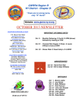
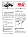
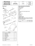
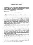
Accessory
Application
HEATED GRIP
WITH THERMOSTAT
P/N 08T50-MCA-102
INSTALLATION
INSTRUCTIONS
Publications No.
GL1800
Issue Date
July 2005
Honda Dealer: Please give a copy of these instructions to your customer.
PARTS LIST
TOOLS AND SUPPLIES REQUIRED
Phillips ® screwdriver
Electric drill motor
Hole saw (45 mm)
Isopropyl alcohol
Pro Honda Handgrip Cement
Scissors
Scale
Electrical Tape
Shop towel
Wood block
Marker
Torque wrench
(1)
(2)
(5)
(7)
(6)
(6)
TORQUE CHART
(8)
(4)
(8)
Tighten all screws, bolts and nuts to their specified torques.
Refer to the Service Manual for the tightening torques of
removed parts.
Item
4 mm screw
(9)
N·m
kgf·m
Ibf·ft
1
0.1
0.7
WIRING DIAGRAM
(11)
(10)
(8)
HEATER HARNESS
R
FUSE 5A
No.
Description
Qty
(1)
Right grip heater
1
(2)
Left grip heater
1
(3)
Switch
1
(4)
Heater harness
1
(5)
Clearance gauge
1
(6)
Grip spacer
2
(7)
Wire tie
12
(8)
4 mm screw
3
(9)
Switch plate
1
(10)
Corrugated tube
1
(11)
Sponge tape (used from the 03 model on)
1
B/G
R
B
B
W/B
W/B R B/G
B
B
B
B
W/B R B/G
RIGHT
GRIP HEATER
© 2005 American Honda Motor Co., Inc - All Rights Reserved.
08T505-MCA-1021-91
LEFT
GRIP HEATER
MINI
COUPLER
(3-PIN)
HEATER SWITCH
Harness Colors
B
Black
G
Green
R
Red
W
White
1 of 16
1. Remove the left grip from the handlebar pipe.
SPECIFICATIONS
Power source: Battery
Wattage: Approx. 35W (maximum)
Heater specifications: FPC heater
(Flexible Printed Circuit)
ISOPROPYL
ALCOHOL
HEATED AREA
LEFT GRIP HEATER
LEFT GRIP (Save)
FRONT
RIGHT GRIP HEATER
HANDLE END CAP
(Reuse)
INSTALLATION
NOTE:
• Disconnect the negative cable from the battery before
installing this accessory.
• The memories of the tripmeter, clock, radio and
suspension system will be erased when you
disconnect the battery. Reset the memories after
reconnecting the battery.
• Tighten the screws, bolts and nuts securely.
• Disconnect the throttle cable from the right grip as
instructed in the motorcycle’s Service Manual.
• For secure adhesion of the grip heaters use the
recommended adhesive agent (Honda Bond A) or
equivalent.
• Reinstall the removed parts on the motorcycle and
make sure that the wires and harnesses are not
pinched.
• After handle grip heater installation, check the lights
(e.g. right / left turn signal lights and brake lights) for
proper operation.
• Be sure to open and close the throttle to check for
smooth operation after installation of the right grip
heater.
• Trim the excess ends off the wire ties after attaching
them to the wire harnesses.
2 of 16
SCREW
(Reuse)
2. Using a Isopropyl alcohol, remove all traces of
adhesive from the handlebar pipe.
08T50-MCA-1021-91
ISOPROPYL
ALCOHOL
HANDLEBAR PIPE
© 2005 American Honda Motor Co., Inc - All Rights Reserved.
3. Remove the right grip from the handlebar pipe as
described in the Service Manual.
5. Liberally apply the Pro Honda Handgrip Cement to the
inside of the left grip heater from the kit as shown.
NOTE
Read the Instructions of the steps 5 through 7 carefully
before operation and complete the installation quickly
before the adhesive agent cures. Use an assistant to
steady the motorcycle while installing the grips.
HANDLEBAR PIPE
Pro Honda
Handgrip Cement
LEFT GRIP HEATER
RIGHT GRIP
SCREW (Reuse)
HANDLE END CAP
(Reuse)
4. Remove the throttle inner grip from the right grip.
6. Spray isopropyl alcohol over the inside of the grip
heater and outside of the left handlebar pipe.
• This is done to ease alignment between the
grip
heater and inner grip.
ISOPROPYL
ALCOHOL
ISOPROPYL
ALCOHOL
THROTTLE INNER GRIP
(Reuse)
LEFT GRIP HEATER
RIGHT GRIP
(Save)
© 2005 American Honda Motor Co., Inc - All Rights Reserved.
08T50-MCA-1021-91
3 of 16
7. Slide the left grip heater onto the handlebar pipe as
indicated.
• Wipe up excess adhesive at once.
8. Install the grip spacer as shown.
NOTE
• Do not tap on the grip end with a hammer and do not
twist the grip with force to insert the inner grip into the
grip heater. It can cause damage to the grip heater
wire.
• If the grip gets stuck halfway during installation, apply
isopropyl alcohol to the gap between the grip heater.
Do not try to remove the heater grip using force or a
screwdriver, etc. Damage to the grip heater wire can
result.
GRIP
SPACER
SCREW
(Reuse)
HANDLE END CAP
(Reuse)
GRIP SPACER AS INSTALLED
• There should be no clearance between the handle end cap
and grip spacer.
HANDLE END CAP
GRIP SPACER
RIGHT GRIP
HEATER
LEFT GRIP HEATER
INSTALLATION of LEFT GRIP HEATER
9. Using a scale and a marker, measure and mark the
harnesses of the right grip heater as shown.
MARKER
LEFT GRIP
HEATER
3.8 mm
HANDLEBAR
PIPE
150 mm
FRONT
RIGHT GRIP HEATER
60½ (Approx)
LEFT GRIP HEATER
HARNESS
4 of 16
08T50-MCA-1021-91
© 2005 American Honda Motor Co., Inc - All Rights Reserved.
10. Apply the Pro Honda Handgrip Cement to the outside
of the throttle inner grip and spread it thinly all over the
surface.
NOTE
Read the Instructions of the steps 10 through 12
carefully before operation and complete the installation
quickly before the adhesive agent cures. Use an
assistant to steady the motorcycle while installing the
grips.
12. Using the clearance gauge provided, slide the throttle
inner grip into the right grip heater up to the edge of
the clearance gauge. Install the right grip in the reverse
order of removal.
• Wipe up excess adhesive at once.
RIGHT GRIP HEATER
THROTTLE INNER GRIP
CLEARANCE GAUGE
Remove after installing
the inner grip.
Pro Honda
Handgrip Cement
THROTTLE
INNER GRIP
NOTE
• Do not tap on the grip end with a hammer and do not
twist the grip with force to insert the inner grip into the
grip heater. It can cause damage to the grip heater
wire.
11. Spray isopropyl alcohol over the inside of the right grip
heater and outside of the throttle inner grip.
• This is done to ease alignment between the
grip
heater and inner grip.
• If the grip gets stuck halfway during installation, apply
isopropyl alcohol to the gap between the grip heater.
Do not try to remove the heater grip using force or a
screwdriver, etc. Damage to the grip heater wire can
result.
• Obtain 5 mm of clearance between the right grip heater
and throttle inner grip using the clearance gauge.
Install the throttle inner grip so that the right grip heater
harness is routed as shown when it is connected to
the motorcycle.
THROTTLE INNER GRIP
RIGHT GRIP HEATER
THROTTLE INNER GRIP
RIGHT GRIP HEATER
5 mm
FRONT
ISOPROPYL
ALCOHOL
© 2005 American Honda Motor Co., Inc - All Rights Reserved.
60½ (Approx)
RIGHT GRIP
HEATER HARNESS
08T50-MCA-1021-91
5 of 16
16. Remove the parts from the motorcycle as indicated in
the Service Manual.
- Up to 02 year model -
13. Install the grip spacer and handle end cap.
RIGHT PASSENGER
GRIP
BOLT
LEFT PASSENGER
GRIP
SEAT
RIGHT SIDE
COVER
GRIP SPACER
Pro Honda
Handgrip Cement
HANDLE END
CAP
(Reuse)
SCREW
(Reuse)
LEFT SPEAKER
COVER
RIGHT SPEAKER
COVER
METER PANEL
14. Open and close the throttle to check that it moves
freely without binding.
15. Remove the left side cover and disconnect the
negative terminal from the battery.
SWITCH COVER
RIGHT FRONT POCKET
Also remove the left side.
BATTERY
CABLE
COVER
LEFT HANDLE
PLATE
RIGHT HANDLE
PLATE
HANDLE
CENTER COVER
RIGHT SHELTER
SWITCH PANEL
Also remove the
left side.
SHELTER
CLIP
LEFT SIDE COVER
RIGHT COWL TRIM
MOULDING
Also remove the
left side.
6 of 16
08T50-MCA-1021-91
© 2005 American Honda Motor Co., Inc - All Rights Reserved.
- From 03 to 05 year model LEFT SPEAKER
COVER
- From 06 year model -
RIGHT SPEAKER
COVER
RIGHT PASSENGER
GRIP
METER PANEL
BOLT
LEFT PASSENGER
GRIP
SWITCH COVER
SEAT
RIGHT FRONT POCKET
Also remove the left
side.
LEFT HANDLE
PLATE
RIGHT HANDLE
PLATE
RIGHT SIDE
COVER
HANDLE
CENTER COVER
RIGHT SHELTER
SWITCH PANEL
Also remove the
left side.
METER PANEL
RIGHT FRONT POCKET
Also remove the left
side.
LEFT HANDLE
PLATE
RIGHT HANDLE
PLATE
RIGHT COWL TRIM
MOULDING
Also remove the
left side.
RIGHT SHELTER
SWITCH PANEL
Also remove the
left side.
RIGHT COWL TRIM
MOULDING
Also remove the
left side.
© 2005 American Honda Motor Co., Inc - All Rights Reserved.
08T50-MCA-1021-91
7 of 16
17. Locale the “x” mark on the back side of the right shelter
switch panel. Drill a hole at the mark using an electric
drill motor and 45 mm hole saw.
• Remove any burr after the hole has been
opened.
RIGHT SHELTER
SWITCH PANEL
ELECTRIC DRILL MOTOR
(45 mm HOLE SAW)
MARK
20. Disconnect the radiator breather hose as shown and
cut it by the dimension shown in the figure.
• Before starting the work, cover the painted
surfaces with shop towels or similar, as coolant
may damage the painted surfaces if it sticks to
them. If coolant should get onto any painted
surfaces, wash it off immediately with water.
• Perform the work only after the engine has
cooled down sufficiently and the water
temperature has dropped. After the work has
been completed, tighten the hose band again.
BOLT
Loosen.
HOSE BAND
(Reuse)
WOOD BLOCK
18. Remove the heater switch from the heater switch
bracket.
• The procedures from the steps 18 through 27
shall be applied to vehicles up to 05 year model.
100 mm
SCISSORS
RADIATOR BREATHER HOSE
SCREW (Reuse)
21. Mark the radiator breather hose with a felt-tip marker
at the dimension shown in the figure.
HEATER SWITCH BRACKET
(Reuse)
HEATER SWITCH (Reuse)
19. Install the heater switch bracket to the right shelter
switch panel as shown.
4 mm
SCREW
30 mm
HEATER SWITCH BRACKET
(Reuse)
MARKER
RADIATOR BREATHER HOSE
RIGHT SHELTER SWITCH PANEL (Reuse)
8 of 16
08T50-MCA-1021-91
© 2005 American Honda Motor Co., Inc - All Rights Reserved.
22. Route the radiator breather hose as shown.
24. Install the radiator breather hose in reverse order of
the disconnection.
BOLT
Tighten.
Top view
RADIATOR BREATHER HOSE
passed through the CORRUGATED
TUBE.
RADIATOR BREATHER
HOSE
Pass underneath the
harness boot.
HOSE BAND (Reuse)
25. Install the right shelter switch panel provisionally and
arrange so that there is no interference between the
radiator breather hose and the key lock ring when
the key is turned.
KEY LOCK RING PART
HARNESS BOOT
23. Pass the radiator breather hose through the
corrugated tube and fix the tube with tape.
RADIATOR BREATHER HOSE
MARK
RIGHT SHELTER SWITCH
PANEL
CORRUGATED TUBE
Slide onto the radiator breather
hose.
TAPE
Fix the corrugated tube with
tape to the radiator breather at
the marked part.
© 2005 American Honda Motor Co., Inc - All Rights Reserved.
RADIATOR BREATHER HOSE
passed through the CORRUGATED
TUBE.
26. Remove the right shelter switch panel and remove
the heater switch bracket.
27. Install the heater switch bracket to the heater switch.
08T50-MCA-1021-91
9 of 16
28. Install the heater switch on the right shelter switch
panel using 4mm screws. Remove the paper backing
from the switch plate and press it into place.
Align the end of the heater switch knob with the
mark on the switch panel.
RIGHT SHELTER
SWITCH PANEL
KNOB
ISOPROPYL
ALCOHOL
SWITCH PLATE
Remove the
adhesive backing
before attaching.
4 mm SCREW
HEATER SWITCH
29. Route and connect the wire harnesses as shown.
HEATER HARNESS
- Up to 02 year model -
MOTORCYCLE’S PIPE
MOTORCYCLE’S 3-PIN
CONNECTOR (NATURAL)
HEATER HARNESS
3-PIN CONNECTOR
(RED)
LEFT HEATER HARNESS
TERMINALS
(WHITE/BLACK, BLACK)
RIGHT HEATER
HARNESS
TERMINALS
(RED, BLACK)
RIGHT GRIP
HEATER HARNESS
LEFT GRIP
HEATER HARNESS
RIGHT HEATER
HARNESS
TERMINALS
(RED, BLACK)
LEFT HEATER HARNESS
TERMINALS
(WHITE/BLACK, BLACK)
10 of 16
08T50-MCA-1021-91
© 2005 American Honda Motor Co., Inc - All Rights Reserved.
- From 03 to 05 year model SOCKET BOLT
MOTORCYCLE’S
HARNESS
LEFT GRIP
HEATER HARNESS
LEFT HEATER HARNESS
TERMINALS
(WHITE/BLACK, BLACK)
HEATER HARNESS
LEFT HEATER HARNESS
TERMINALS
(WHITE/BLACK, BLACK)
RIGHT HEATER HARNESS
TERMINALS
(RED, BLACK)
MOTORCYCLE’S 3-PIN
CONNECTOR (RED)
RIGHT GRIP
HEATER HARNESS
RIGHT HEATER
HARNESS
TERMINALS
(RED, BLACK)
HEATER HARNESS 3-PIN
CONNECTOR (RED)
© 2005 American Honda Motor Co., Inc - All Rights Reserved.
HEATER HARNESS
08T50-MCA-1021-91
11 of 16
- From 06 year model -
LEFT GRIP
HEATER HARNESS
LEFT HEATER HARNESS
TERMINALS
(WHITE/BLACK, BLACK)
HEATER HARNESS
LEFT HEATER HARNESS
TERMINALS
(WHITE/BLACK, BLACK)
RIGHT HEATER HARNESS
TERMINALS
(RED, BLACK)
HEATER HARNESS 3-PIN
CONNECTOR (RED)
MOTORCYCLE’S 3-PIN
CONNECTOR (RED)
RIGHT GRIP
HEATER HARNESS
RIGHT HEATER
HARNESS
TERMINALS
(RED, BLACK)
12 of 16
08T50-MCA-1021-91
© 2005 American Honda Motor Co., Inc - All Rights Reserved.
30. Secure the wire harnesses with the wire ties in the areas
shown.
• Turn the handlebar to the extreme right and left to check
that the wire harnesses are not pulled taut.
• Push the grip heater harness into handle plate.
- Up to 02 year model -
After squeezing the wire tie, check that the
wire harness is not sagged or pulled taut by
opening and closing the throttle several times.
After connecting, wrap an electrical tape
around the terminals.
WIRE TIES
Secure to the
motorcycle’s harness.
WIRE TIE
Secure to the motorcycle’s
harness at the marked location.
RIGHT GRIP
HEATER HARNESS
ELECTRICAL TAPE
WIRE TIES
Secure to the
motorcycle’s pipe
Route the wire harness avoiding the radiator cap;
then, secure the harness with the wire tie and
install the right shelter switch panel.
MOTORCYCLE’S HARNESS CLAMP
Secure to the motorcycle’s pipe.
MOTORCYCLE’S
PIPE
RIGHT SHELTER
SWITCH PANEL
FUSE
WIRE TIES
Secure to the
motorcycle’s harness.
RADIATOR CAP
© 2005 American Honda Motor Co., Inc - All Rights Reserved.
08T50-MCA-1021-91
13 of 16
- From 03 to 05 year model After squeezing the wire tie, check that the
wire harness is not sagged or pulled taut by
opening and closing the throttle several times.
After connecting, wrap an electrical tape
around the terminals.
ELECTRICAL TAPE
WIRE TIES
Secure to the
motorcycle’s harness.
WIRE TIE
Secure to the motorcycle’s
harness at the marked location.
Route the wire harness avoiding the radiator cap; then,
secure the harness with the wire tie and install the right
shelter switch panel.
RIGHT GRIP
HEATER HARNESS
SPONGE TAPE
Fix the harness.
WIRE TIES
Secure to the
motorcycle’s harness.
RIGHT SHELTER
SWITCH PANEL
14 of 16
FUSE
RADIATOR CAP
RADIATOR CAP
08T50-MCA-1021-91
© 2005 American Honda Motor Co., Inc - All Rights Reserved.
- From 06 year model After squeezing the wire tie, check that the
wire harness is not sagged or pulled taut by
opening and closing the throttle several times.
After connecting, wrap an electrical tape
around the terminals.
ELECTRICAL TAPE
WIRE TIES
Secure to the
motorcycle’s harness.
WIRE TIE
Secure to the motorcycle’s
harness at the marked location.
Route the wire harness avoiding the radiator cap; then,
secure the harness with the wire tie and install the right
shelter switch panel.
RIGHT GRIP
HEATER HARNESS
SPONGE TAPE
Fix the harness.
FUSE
RADIATOR
CAP
WIRE TIES
Secure to the harness.
RIGHT SHELTER
SWITCH PANEL
© 2005 American Honda Motor Co., Inc - All Rights Reserved.
CLAMP
Hold the bundled
wire harness.
RADIATOR CAP
08T50-MCA-1021-91
15 of 16
31. Reinstall all removed parts.
32. Reconnect the negative cable to the battery.
33. Check the following:
• Operation of the grip heaters.
• Smooth operation of the throttle without binding.
• Operation of all lights.
OPERATION
• Do not operate the grip heater switch during driving.
• Wear gloves whenever operating the handle grip
heater.
• Do not operate the handle grip heater with worn or
torn surface rubber. Replace the handle grip heater
with a new one.
• The grip heater is connected to the DC circuit from
the battery. The grip heater is incorporated with the
automatic switch that turns ON/OFF by detecting the
voltage to prevent dead battery. Therefore, the switch
can turn OFF automatically when the battery voltage
drops, e.g. when the motorcycle comes to a halt or
when running slowly. The switch turns ON
automatically when the battery voltage rises and the
motorcycle is running at a normal driving speed.
• Note that the heater temperature is proportional to
the atmospheric temperature. Do not set the grip
heater at “Hi” position when the atmospheric
temperature is high (20½C or above).
• When the motorcycle is crawling along, the automatic
switch may or may not turn ON according to the battery
condition when the heater switch is turned ON.
• Use only the 5A fuse to replace the grip heater fuse.
• The battery is a consumable part and the grip heater
does not operate when the battery runs down. Check
the battery periodically and replace if necessary.
USER TROUBLESHOOTING
• Check the following if the grip heaters do not operate
properly.
• If the grip heaters do not operate after following the
troubleshooting procedures, contact your local Honda
motorcycle dealer.
Symptom
Check
Grip heater does not
operate at all or
temperature cannot
be adjusted properly.
1. Is the engine running?
2. Is the heater switch between the
Hi and Lo positions with the
engine running?
3. Check by raising the engine
speed.
Heater temperature is
too low or too high.
1. Is the heater temperature set
between Hi and Lo?
2. Is the motorcycle frequently
operated at idle or low speed?
3. If the temperature is too high,
move the switch to the Lo position
or turn the switch Off, or wear
thick gloves.
Grip heater is partly
warmed.
1. This is not a problem. Heat is
concentrated at the finger part.
DEALER TROUBLESHOOTING
• Stop the engine and turn the main switch OFF when
you check the parts and circuits other than those of
the grip heaters.
Symptom
Check
Grip heater does not
operate;
• Faulty grip heater
• Faulty grip heater
coil
• Blown fuse
• Open or short circuit
in heater harness
• Faulty heater switch
1. Check whether wires and cables
(terminals and connectors) are
connected securely.
2. Grip heater inspection
Check for resistance between the
terminals.
Standard:
Right: 2.2 ohms +/- 10%
Left : 2.2 ohms +/- 10%
3. Heater harness inspection:
Check for continuity by referring
to the wiring diagram.
4. If no abnormality is found after the
above checks 1, 2, and 3, but the
grip heater still does not operate
properly, replace the heater
switch with a new one.
• It is hard to check the switch in
ordinary inspection method (for
continuity etc.) because it
contains an IC circuit.
16 of 16
08T50-MCA-1021-91
© 2005 American Honda Motor Co., Inc - All Rights Reserved.