1
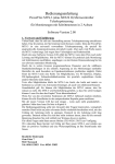
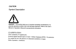
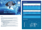
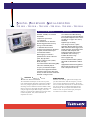
I G I TA L
H O SP H O R
SC I L L O SC O P E S
TD S 30 12 • TD S 30 14 • TD S 30 32 • TD S 30 34 • TD S 30 52 • TD S 30 54
EATU RES A N D
EN EFI TS
500 MHz, 300 MHz, and 100 MHz
Bandwidths
PP LI CATI O N S
2 or 4 Channels
Telecommunications Manufacturing
(Telecom Mask Test Application Module
for Pass/Fail Compliance of ITU-T G.703
and ANSI T1.102 (Up to STS-1 Rates)
Standards)
Full VGA Color LCD on all Models
Digital Design and Debug
Built-in Floppy Disk Drive For Easy
Storage and Documentation
Video Design and Service (Video
Application Modules Offer Line Count,
HDTV and Custom Video Trigger, Video
Display Graticules, SDI to Analog Video
Conversion with Composite and
Component Outputs, Video Picture
Identification and Vectorscope)
Sample Rates up to 5 GS/s
21 Automatic Measurements
Centronics Port Standard on all Models
for Quick, Convenient Hardcopies
9-bit Vertical Resolution
Multi-Language User Interface
QuickMenu User Interface Mode for
Quick, Easy Operation
Advanced Triggers, such as, Glitch,
Width, and Logic
Telecommunications Mask Testing (TMT)
Fast Fourier Transform (FFT) for
Frequency and Harmonic Analysis
Industrial Electronic Design
Power Supply Design
Connected Instrumentation (10Base-T
LAN, GPIB and VGA Modules with RS232)
Highly Mobile Environments (Optional
Battery Pack for Convenient Use in the
Field or Away from the Bench)
Extended Video Application Module
Support for Active Probes, Differential
Probes, and Current Probes that Provide
Automatic Scaling and Units
T
H E
H O SP H O R
ERI ES O F
SCI LLO SCO PES
I GI TA L
Th e TDS 3000 oscilloscop es are th e low est p riced ,
m ost p ortable Digital Ph osp h or Oscilloscop es (DPOs).
Now every d esign en gin eer an d tech n ician can take
ad van tage of th e trem en d ou s ben efits of DPOs. DPOs
d eliver a n ew level of in sigh t th at m akes d ealin g w ith
com p lex sign als sim p le. DPOs d isp lay, store, an d
an alyze, in real-tim e th ree d im en sion s of sign al in form ation : am p litu d e, tim e, an d d istribu tion of
am p litu d e over tim e.
BENEFITS OF DPO
DPOs h ave an in ten sity grad ed color d isp lay th at
p rovid es in form ation abou t th e frequ en cy of occu rren ce of sign al am p litu d es an d w id th s. Th is h elp s
th e u ser locate an d ch aracterize w aveform an om alies
th at can be elu sive on trad ition al Digital Storage
Oscilloscop es. Th e fast u p d ate rate of DPOs also
m akes it easier to cap tu re an d d isp lay in frequ en t
w aveform s or w aveform variation s.
®
QUICK TO LEARN AND QUICK TO USE
Th e TDS 3000 Series grap h ical u ser in terface offers a n ew op eratin g m od e called
Qu ickMen u . Th is qu ick access u ser in terface m akes th e m ain oscilloscop e con trols
accessible w ith a p u sh of a sin gle bu tton .
In clu d ed w ith every scop e is an On -Lin e
Tou r d isk th at ru n s in th e oscilloscop e.
Th is d isk gives an overview of th e p rod u ct’s op eration an d cap abilities.
FLEXIBLE FEATURES FOR EVERY
APPLICATION
Th e p ortable form factor allow s th e
in stru m en t to go w h erever it is n eed ed .
Th e Com m u n ication an d Ap p lication
Mod u les en able th e in stru m en t to be con figu red for sp ecific ap p lication s or
u p grad ed w ith ou t retu rn in g it to th e m an u factu rer. Th e TekProbe ® Level II
in terface p rovid es p ow er to a ran ge of
ap p lication sp ecific accessories.
APPLICATION MODULES
With th e ap p lication m od u le con cep t, th e
TDS 3000 Series can be easily ad ap ted to
th e n eed s of th e u ser. Th ese m od u les are
easily in stalled by th e u ser. At p ow er on
th e scop e in d icates w h ich m od u les are
in stalled . Cu rren tly, th ere are five ap p lication m od u les available for th e TDS 3000
Series – a telecom m u n ication s m ask test
m od u le, an FFT m od u le, an ad van ced
trigger m od u le, a 601 d igital vid eo m od u le
an d an exten d ed vid eo m od u le. In ad d ition , th ere are th ree com m u n ication
m od u les available – a 10Base-T LAN/ RS232 m od u le, a GPIB/ RS-232 m od u le an d a
VGA/ RS-232 m od u le. Cen tron ics p ort is
stan d ard .
CH A R A CTERI STI C S
ERI ES
Bandwidth
Channels
Sample Rate on Each Channel
Maximum Record Length
Vertical Resolution
Vertical Sensitivity (/div)
Vertical Accuracy
Max Input Voltage (1 MΩ)
Position Range
BW Limit
Input Coupling
Input Impedance Selections
Time Base:Range (/div)
Accuracy
Display Monitor
L E C T R I C A L H A R A C T E R I ST I C S
TDS 3012
100 MHz
2
1.25 GS/s
20 MHz
4 ns – 10 s/div
200 ppm
TDS 3032
300 MHz
2
2.5 GS/s
TDS 3052
TDS 3014
500 MHz
100 MHz
2
4
5 GS/s
1.25 GS/s
10K points on all models
9-bits on all models
1 mV-10 V on all models
±2% on all models*
150V RMS CAT I on all models
± 5 div on all models
20, 150 MHz
20, 150 MHz
20 MHz
AC, DC, GND on all models
1 MΩ in parallel with 13 pF, or 50 Ω
2 ns – 10 s/div
1 ns – 10 s/div
4 ns – 10 s/div
200 ppm
200 ppm
200 ppm
Color LCD
TDS 3034
300 MHz
4
2.5 GS/s
TDS 3054
500 MHz
4
5 GS/s
20, 150 MHz
20, 150 MHz
2 ns – 10 s/div
200 ppm
1 ns – 10 s/div
200 ppm
* Derated at 0.07% / °C for tem p eratu res above +28°C an d below +18°C.
ACQUISITION MODES
TRIGGER TYPES
Peak Detect – High frequency and random
glitch capture. Captures glitches as narrow as
1 ns.
Sample – Sample data only.
Envelope – Max/Min values acquired over one
or more acquisitions.
Average – Waveform data from 2 to 572
(selectable) acquisitions is averaged.
Single Sequence – Use SINGLE SEQUENCE
button to capture a single triggered acquisition
sequence at a time.
Edge – Conventional level-driven trigger. Positive
or negative slope on any channel. Coupling selections: DC, noise reject, HF reject, LF reject.
Video – Trigger on all lines or individual line,
odd/even or all fields, or analog HDTV formats
(1080i, 1080p, 720p, 480p). See optional
TDS 3VID and TDS 3SDI application modules for
extended video triggering and measurement
features.
Logic (Standard on TDS 30X4, must purchase
TDS 3TRG for TDS 30X2) –
PATTERN: Specifies AND, OR, NAND, NOR when
true or false for a specific time.
STATE: Any logic state. Triggerable on rising or
falling edge, of a clock.
Note: Logic triggers can only be used on combinations of 2 inputs.
Pulse (Standard on TDS 30X4, must purchase
TDS 3TRG for TDS 30X2) –
WIDTH (or GLITCH): Trigger on pulse width less
than, greater than, equal to, or not equal to a
selectable time limit ranging from 39.6 ns to 50s.
TRIGGER SYSTEM
M ain Trigger M odes – Auto (supports Roll
Mode for 40 ms/div and slower), Normal.
B Trigger – Trigger after time or events.
Trigger After Time Range – 13.2 ns to 50 s.
Trigger After Events Range – 1 to 9,999,999
events.
External Trigger Input (available on TDS 30X2
only) – >1 MΩ in parallel with 17 pF; Max input
voltage is 150 V RMS.
2
TDS
3000
SERIES
D I G I TA L
RUNT: Trigger on a pulse that crosses one threshold but fails to cross a second threshold before
crossing the first again.
SLEW RATE: Trigger on pulse edge rates that are
either faster or slower than a set rate. Edges can
be rising, falling, or either.
Comm (must purchase TDS 3TMT) – provides
isolated pulse triggering required to perform
DS1/DS3 telecommunications mask testing per
ANSI T1.102 standard.
MEASUREMENT SYSTEM
Automatic W aveform M easurements –
Period, Frequency, +Width, –Width, Rise Time,
Fall Time, +Duty Cycle, –Duty Cycle,
+Overshoot, –Overshoot, High, Low, Max, Min,
Pk-Pk, Amplitude, Mean, Cycle Mean, RMS, Cycle
RMS, Burst Width.
Display any four measurements from any combination of waveforms.
Thresholds – Settable in percentage or voltage.
Gating – Measurements can be gated using the
screen or vertical cursors.
PHOSPHPOR
OSCILLOSCOPES
CH AR ACTERI STI CS ( CO N TI N U ED WAVEFORM PROCESSING
Deskew – Channel to channel deskew ±10 ns
may be manually entered for better timing measurements and more accurate math waveforms.
Arithmetic Operators – Add, Subtract,
Multiply, Divide.
Autoset – Single-button, automatic setup on
selected input signal for vertical, horizontal, and
trigger systems.
DISPLAY CHARACTERISTICS
Graticules – Full, grid, cross-hair, frame, NTSC,
PAL, SECAM, vectorscope 100% and 75% color
bars (with optional TDS 3VID and TDS 3SDI video
application modules).
Format – YT, XY and Gated XYZ (XY with Z-axis
blanking available on TDS 30X4 only).
I/O INTERFACE
Hardcopy Port (standard) – Centronics-type
parallel.
TDS 3GM Communications M odule –
GPIB (IEEE –488.2) Programmability: Full talk/listen modes; Control of all modes, settings, and
measurements.
RS-232-C Interface Programmability: Full talk/listen modes; Control of all modes, settings, and
measurements. Baud Rate up to 38,400. DB-9
male connector.
Programmer Manual: (071-0381-00).
RD ERI N G
STANDARD ACCESSORI ES
Probes: 2 each P3010 10X passive probes (TDS 3012), 4
each P3010 10X passive probes (TDS 3014), 2 each
P6139A 10X passive probes (TDS 3032, TDS 3052), 4
each P6139A 10X passive probes (TDS 3034, TDS 3054).
Documentation: Quick Reference Manual, User Manual,
On-line Tour Disk, Front panel overlay for non-English
languages.
Application Modules (TDS 3014, TDS 3034, TDS 3054
only): TDS 3FFT, TDS 3TRG.
Power Cord.
Accessory Tray.
Protective Front Cover: has holder for reference manual
and/or 3.5 in. floppy disks.
NIST-Traceable Certificate of Calibration.
W ARRANTY I NFORM ATION
Three year warranty covering all labor and parts,
excluding probes.
I NTERNATIONAL POW ER PLUGS
Standard – US (161-0104-00).
Opt. A1 – Universal Euro 220 V, 50 Hz (161-0104-06).
Opt. A2 – United Kingdom 240 V, 50 Hz (161-0104-07).
Opt. A3 – Australia 240 V, 50 Hz (161-0104-05).
Opt. A5 – Switzerland 220 V, 50 Hz (161-0167-00).
Opt. A6 – Japan 3 to 2 wire adapter (013-0310-00).
3000
HARD COPY CAPABILITY
Graphics File Formats – Interleaf (.img), TIF,
PCX (PC Paintbrush), BMP (Microsoft Windows),
and Encapsulated Postscript (EPS).
Printer Formats – Bubblejet, DPU-3445,
Thinkjet, Deskjet, Laserjet, Epson (9 and 24-pin).
ENVIRONMENTAL AND SAFETY
Temperature – +5 to +50°C (operating), –20 to
+60°C (nonoperating).
Humidity – 20% to 80% RH below 32°C, derate to
30% RH at 45°C (operating), 5% to 90% RH below
41°C, derate to 30% RH at 60°C (nonoperating).
Altitude – to 3,000 m (operating), 15,000 m
(nonoperating).
Electromagnetic Compatibility – Meets or
exceeds EN55011 Class A Radiated and
Conducted Emissions; EN50082-1; FCC 47 CFR,
Part 15, Subpart B, Class A; Australian EMC
Framework; Russian GOST EMC regulations.
Safety – UL3111-1, CSA1010.1, EN61010-1,
IEC61010-1.
H Y SI C A L H A R A C T E R I ST I C S
Instrument
Dimensions
Width
Height
Depth
Weight
Instrument only
w/battery
mm
375.0
176.0
149.0
kg
3.2
5.2
in.
14.8
6.9
5.9
lb.
7.0
11.5
N FO RM ATI O N
TDS 3012, TDS 3014, TDS 3032, TDS 3034,
TDS 3052, TDS 3054
TDS
TDS 3VM Communications M odule –
VGA: Monitor output for direct display on large
VGA-equipped monitors. DB-15 female connector,
31.6 kHz sync rate, EIA RS-343A compliant.
RS-232-C Interface Programmability: same as
TDS 3GM.
Programmer Manual: same as TDS 3GM.
TDS 3EM Communications M odule –
Ethernet Port: 10Base-T with RJ-45 connector.
Provides local area network printing and programming interface.
RS-232-C Interface programmability: same as
TDS 3GM.
Programmer Manual: same as TDS 3GM.
Note: Only one Communication Module may be
installed at a time.
All Communication Modules include WaveStar ™
Software for oscilloscopes 30-day, full-functioning
product demo.
SERIES
D I G I TA L
I NTERNATIONAL USER M ANUALS (TDS 3000
SERI ES, TDS 3FFT, TDS 3TRG, TDS 3VI D,
TDS 3TM T)
Standard – English.
Opt. L1 – French.
Opt. L2 – Italian.
Opt. L3 – German.
Opt. L4 – Spanish.
Opt. L5 – Japanese.
Opt. L6 – Portuguese.
Opt. L7 – Simplified Chinese.
Opt. L8 – Traditional Chinese.
Opt. L9 – Korean.
Opt. LR – Russian. (TDS 3000 products only)
I NSTRUM ENT ACCESSORI ES
TDS 3SDI – 601 Digital Video Module.
Converts ITU-R BT.601 format serial digital video to analog video. Automatically detects and displays 525/60
and 625/50 formats. Provides composite and component (RGB, YPbPr, or YC) outputs. Provides auto equalization for cable lengths up to 250 m and EDH and
counting for incoming SDI signal. Adds video picture
mode with on-screen line select and vectorscope mode
with 100% and 75% color bars. Adds triggering and
vectorscope graticules for analog HDTV. Includes full
functionality of TDS 3VID Extended Video Applications
module. Includes special output cable and four 75 Ω
terminators. Ships with Quick Reference and User
Manuals in 10 languages. (Russian not available.)
PHOSPHPOR
OSCILLOSCOPES
TDS 3BAT – Battery Pack being installed.
Application Module being installed.
3
RD ERI N G
N FO RM ATI O N O N TI N U ED TDS 3TM T – Telecom Mask Testing Application
Module. Adds Pass/Fail mask testing for compliance to
telecommunications standards:
• ITU-T G.703 (DS0, DS1, E1, Clk Interface, DS2, E2, E3,
and DS3 rates)
• ANSI T1.102 (DS1, DS1A, DS1C, DS2, DS3, STS-1 rates)
• Customize (edit) masks using WaveStar™ software for
oscilloscopes (Version 2.3) mask editing tool
TDS 3FFT – FFT Application Module (standard on
TDS 30X4). Adds FFT measurement capabilities in dB
or linear RMS scales. A selection of four FFT windows
(Rectangular, Hamming, Hanning, and Blackman-Harris)
are provided.
TDS 3TRG – Advanced Trigger Application Module
(standard on TDS 30X4). Adds Logic and Pulse triggering described under Trigger Types (page 2).
TDS 3VID – Extended Video Application Module. Adds
line count triggering, custom video scan and field rates,
readout in mV or IRE units, and includes 75 Ω terminator.
TDS 3EM – 10Base-T Ethernet (LAN) and RS-232
interfaces.
TDS 3GM – GPIB and RS232 interfaces.
TDS 3VM – VGA port and RS232 interface.
TDS 3BAT – Battery pack for up to 2 hours continuous
operation without line power. Note: the instrument
must be grounded at all times.
TDS 3CHG – Fast charger for battery pack.
AC3000 – Soft case for carrying instrument.
HCTDS32 – Hard plastic case for carrying instrument.
RM 3000 – Rackmount kit.
Service M anual (TDS 3000 Series) – English Only
(071-0382-00).
TDS 3GM , TDS 3VM and TDS 3EM Programmers
M anual – English Only (071-0381-00).
W STRO – WaveStar ™ Software for Oscilloscopes,
Windows 95/98/NT 4.0 Application.
PROBES
ADA400A – 100X, 10X, 1X, 0.1X High gain differential
amplifier.
P6243 – 1 GHz, ≤1pF input C 10X active probe.
P6246 – 400 MHz differential probe.
P5205 – 1.3 kV, 100 MHz high voltage differential
probe.
P5210 – 5.6 kV, 50 MHz high voltage differential probe.
P5100 – 2.5 kV, 100X high voltage passive probe.
TCP202 – 15 A, DC + Peak AC 50 MHz AC/DC current
probe.
For further information, contact Tektronix:
Worldwide Web: for the most up-to-date product information visit our web site at: www.tektronix.com/Measurement/scopes/
ASEAN Countries (65) 356-3900; Australia & New Zealand 61 (2) 9888-0100; Austria, Central Eastern Europe, Greece, Turkey, Malta,& Cyprus +43 2236 8092 0;
Belgium +32 (2) 715 89 70; Brazil and South America 55 (11) 3741-8360; Canada 1 (800) 661-5625; Denmark +45 (44) 850 700; Finland +358 (9) 4783 400;
France & North Africa +33 1 69 86 81 81; Germany + 49 (221) 94 77 400; Hong Kong (852) 2585-6688; India (91) 80-2275577; Italy +39 (2) 25086 501;
Japan (Sony/Tektronix Corporation) 81 (3) 3448-3111; Mexico, Central America, & Caribbean 52 (5) 666-6333; The Netherlands +31 23 56 95555; Norway +47 22 07 07 00;
People’s Republic of China 86 (10) 6235 1230; Republic of Korea 82 (2) 528-5299; South Africa (27 11)651-5222; Spain & Portugal +34 91 372 6000;
Sweden +46 8 477 65 00; Switzerland +41 (41) 729 36 40; Taiwan 886 (2) 2722-9622; United Kingdom & Eire +44 (0)1344 392000; USA 1 (800) 426-2200.
From other areas, contact: Tektronix, Inc. Export Sales, P.O. Box 500, M/S 50-255, Beaverton, Oregon 97077-0001, USA 1 (503) 627-6877.
Copyright © 2000, Tektronix, Inc. All rights reserved. Tektronix products are covered by U.S. and foreign patents, issued and pending.
Information in this publication supersedes that in all previously published material. Specification and price change privileges reserved.
TEKTRONIX and TEK are registered trademarks of Tektronix, Inc. All other trade names referenced are the service marks,
trademarks or registered trademarks of their respective companies.
4/00
HB/XBS
3GW-12482-4