1
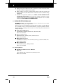
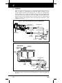
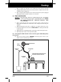
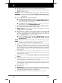
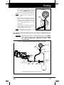
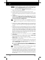
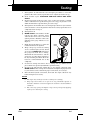
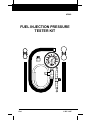
#3640
FUEL INJECTION PRESSURE
TESTER KIT
Fuel
© IEC 1997
Table of Contents
Paragraph
Title
Page No.
GENERAL INFORMATION
1.1
1.2
1.3
1.4
1.5
ABOUT THE TESTER .....................................................................
VEHICLES COVERED ....................................................................
BEFORE YOU BEGIN .....................................................................
SAFETY PRECAUTIONS ................................................................
VEHICLE SERVICE MANUALS ....................................................
1-1
1-2
1-2
1-3
1-4
TESTING
2.1
2.2
GENERAL .........................................................................................
TEST PROCEDURES.......................................................................
2-1
2-2
WARRANTY AND SERVICE
3.1
3.2
i
LIMITED ONE YEAR WARRANTY................................................
SERVICE PROCEDURES................................................................
3-1
3-1
Fuel
1
General Information
1.1 ABOUT THE TESTER
The Fuel Injection Pressure Tester Kit is designed to perform fuel pressure
tests on most domestic and import cars and trucks. The tester saves you time and
money by helping you test and troubleshoot fuel system problems which can
affect your vehicle's performance and fuel economy.
The tester can help you identify and diagnose:
•
•
•
•
•
Low fuel pump pressure
Faulty fuel pressure regulator
Leaking fuel injectors
Clogged fuel filter
Leaks in the fuel system
1.1.1 Fuel Injection Pressure Tester Kit Components (see Figure 1)
Figure 1. Fuel Injection Pressure Tester Kit Components
1
6
9
10
8
7
2
5
3
4
1.
Tester Gauge. Shows fuel pressure in system during test.
2.
Relief Valve. Relieves pressure in the fuel system during and after
testing.
3.
Bleed-Off Hose. Drains bleed-off fuel into a suitable container.
4.
Gauge Hose. High pressure hose with threaded female connector;
connects to the vehicle's fuel system test port.
5.
Tee Fitting. Universal fitting with built-in test port. Allows the tester to
be used on some vehicles not factory-equipped with a test port (Schrader
valve).
Engine
1-1
1
6.
Ford Adapter. Installs on the fuel system test port of Ford and some
Chrysler vehicles to allow connection of the tester.
7, 8.
Hose. 5/16" and 3/8" universal high-pressure hoses used in conjunction
with tee fitting (5).
9, 10. Hose Clamp. High-pressure fuel line clamps used in conjunction with
hoses (7, 8) and tee fitting (5).
NOTE:
The adapters provided with the tester are designed to facilitate the
most common fuel injection system applications. Some vehicle
applications may require additional tools or adapters to properly test
the vehicle. Refer to your vehicle's service manual, and consult your
auto parts dealer for the availability of these items.
1.2 VEHICLES COVERED
1.2.1 Domestic Vehicles (1980-98)
•
Dodge, Chrysler, Plymouth
•
Ford, Lincoln, Mercury
•
GMC, Chevrolet, Buick,
Oldsmobile, Pontiac, Saturn,
Cadillac
•
Jeep, Eagle
Fuel System Type/Applications
•
All electronic fuel injection
systems (port, sequential,
multi-point, throttle body),
which are equipped with a
fuel pressure test port
(Schrader valve)
•
All fuel injection systems
(without a fuel pressure test
port) equipped with flexible
rubber fuel supply lines
1.2.2 Import Vehicles (1980-98)
•
Geo
•
Includes light trucks and vans
•
Isuzu
•
Excludes diesel
•
Mazda
•
Nissan
•
Subaru
•
Suzuki
•
Volkswagen
1.3 BEFORE YOU BEGIN
•
Fix any known mechanical problems before performing any test.
WARNING:
1-2
Please be aware that fuel systems are UNDER PRESSURE
AND HIGHLY FLAMMABLE. In addition to following all
safety precautions, a basic understanding of fuel systems is
necessary. Read this manual thoroughly to prevent
accidents, personal injury and/or damage to your vehicle.
•
If a further understanding of fuel injection systems is necessary, many
publications covering this topic are available.
•
Your vehicle’s service manual can give you specialized test procedures and
repair methods which can make your job easier. READ YOUR
VEHICLE’S SERVICE MANUAL.
•
Keep a pencil and paper handy to make notes and record test results.
Fuel
General Information
a.
Read and follow all safety precautions.
b.
Make sure the battery is fully charged and the vehicle has enough fuel in
the tank.
c.
Perform a thorough underhood inspection. Check for loose or cracked
electrical wiring, battery cables, ignition wires, fuel and/or vacuum lines.
Perform necessary repairs and ensure the fuel system is leak-free. WIPE
UP ANY FUEL LEAKS IMMEDIATELY.
d.
Verify all related fuses are in good condition. Verify integrity of all
electrical component connections.
e.
For Ford vehicles ONLY: Make sure the inertia switch (the fuel system’s
safety switch) is not tripped and is operating properly. (Refer to your
vehicle’s service manual for location.)
f.
Check the vapor recovery system and fuel tank cap for proper operation.
g.
Make sure the intake (engine) vacuum is within original manufacturer’s
specifications.
h.
If the engine does not start, refer to your vehicle’s service manual for proper
diagnostic procedures.
1.4 SAFETY PRECAUTIONS
•
Read this manual COMPLETELY before performing any test
procedures.
•
Always observe safety precautions whenever working on a vehicle.
a.
Always wear safety eye protection.
b.
Only work on your vehicle in a well-ventilated area.
c.
Put transmission in PARK (automatic transmission) or NEUTRAL (manual
transmission). Set parking brake.
d.
Put blocks on the drive wheels.
e.
Release fuel system pressure before connecting test equipment or
performing tests (refer to your vehicle’s service manual for
procedures).
f.
Make sure the ignition is off before connecting or disconnecting any test
equipment.
g.
Never connect the Fuel Injection Tester to any location other than those
indicated in the test procedures (many air conditioning fittings resemble
fuel injection test ports).
h.
Fuel and battery vapors are highly flammable. DO NOT SMOKE NEAR
THE VEHICLE DURING TESTING.
i.
DO NOT attempt to use this tool on systems not covered in this manual.
j.
During testing, be careful to avoid fuel spills on hot engine parts. If spills
occur or if leaks are present, turn ignition off IMMEDIATELY and correct
the problem. WIPE UP FUEL SPILLS IMMEDIATELY.
k.
Avoid moving fan blades or any potentially moving parts.
l.
Avoid hot engine parts. Keep tools away from the battery to avoid possible
shorting and sparks which could start a fire.
m. In case of emergency, keep a fire extinguisher handy. MAKE SURE it is
rated for fuel/electrical and chemical fires.
Fuel
n.
NEVER leave the vehicle unattended during testing.
o.
Take care when working near ignition system components (coil, distributor
cap, ignition wires, etc). These are all HIGH VOLTAGE areas.
1-3
1
p.
When placing the bleed-off hose into a container to collect excess fuel, make
sure the container is approved for gasoline.
q.
When working on vehicles equipped with airbags, follow all cautions and
test procedures in your vehicle’s service manual to avoid accidental airbag
deployment.
r.
Gasoline and gasoline additives are TOXIC. AVOID CONTACT OF
GASOLINE WITH SKIN. Wear protective clothing and hand covering
(approved latex gloves) when performing pressure tests. In case of contact
with skin, WASH THE AREA IMMEDIATELY.
1.5 VEHICLE SERVICE MANUALS
You MUST consult the manufacturer’s service manual for your vehicle
BEFORE performing any test procedures.
Contact your local car dealership, auto parts store, bookstore or public library
for availability of these manuals. The following companies publish valuable
repair manuals, including material that covers fuel injection systems and
testing techniques.
■
Chek-Chart Publications
1515 Grandview Parkway, Sturtevant, Wisconsin 53117
Phone (800) 662-6277
■
Haynes Publications
861 Lawrence Dr., Newbury Park, California 91320
Phone (805) 498-6703
■
Mitchell International
9889 Willow Creek Rd., P. O. Box 26260, San Diego, California 92196-0260
Phone (619) 578-6550
■
Motor Publications
5600 Crooks Rd., Troy, Michigan 48098
Phone (800) 426-6867
1.5.1 Factory Manuals
■
1-4
Ford/General Motors Service Manuals
Helm Inc.
14310 Hamilton Ave., Highland Park, Michigan 48203
Phone (800) 782-4356
Fuel
General Information
Fuel
1-5
2
2.1 GENERAL
The tests outlined in this manual are for checking Throttle Body Fuel Injection
(TBI) (see Figure 2) and Multi-port Fuel Injection (MFI) (see Figure 3) fuel
system pressures with the engine running (key on, engine on) and without the
engine running (key on, engine off). Engine running tests are performed with
the engine at idle (unless otherwise noted). The adapter for testing GM vehicles
with test ports is already installed on the end of the gauge hose, while the Ford
adapter is separate. For Chrysler vehicles, depending upon application, either
adapter may be used.
Figure 2. Typical Throttle Body Fuel Injection (TBI) System
THROTTLE BODY
PRESSURE REGULATOR
FLEXIBLE HOSE
FUEL RETURN LINE
FUEL PRESSURE LINE
FUEL CAP
TBI UNIT
FUEL INJECTORS
IN-LINE
FUEL FILTER
FUEL TANK
IN-TANK
FUEL PUMP
PUMP INLET
FILTER
Figure 3. Typical Multi-Port Fuel Injection (MFI) System
MANIFOLD VACUUM
HOSE CONNECTION
PRESSURE
REGULATOR
TEST PORT
(SCHRADER
VALVE)
PULSE
DAMPENER
FUEL RETURN LINE
FUEL INJECTORS
FUEL PRESSURE LINE
FUEL
CAP
FLEXIBLE
HOSE
IN-LINE
FUEL FILTER
PULSATOR
FUEL TANK
IN-TANK
FUEL PUMP
PUMP INLET
FILTER
Some fuel injection systems are not equipped with a test port (Schrader valve).
In some cases, these systems may be tested using the tee adapter provided with
the tester:
2-1
Fuel
Testing
•
The tee adapter is suitable for use with most fuel injection systems
equipped with rubber fuel hoses secured by fuel line clamps at the fuel rail
or throttle body (see Figure 6).
•
The tee adapter is not suitable for use with fuel injection systems equipped
with rigid, metallic or plastic fuel lines or connectors.
2.2 TEST PROCEDURES
WARNING:
Fuel injection systems are under high pressure. You MUST
relieve system pressure before connecting the tester. REFER
TO YOUR VEHICLE'S SERVICE MANUAL FOR
PROCEDURES.
•
Before connecting the tester to the fuel system, apply a small amount of
light grade household oil or lubricant to the o-rings located in the port
adapters.
•
When attaching the gauge hose or adapters to test ports, make sure you use
the proper adapter for your vehicle. TAKE CARE not to damage the threads
on the test port.
•
•
Wrap shop rags around fitting when connecting or disconnecting the tester.
Have shop rags ready to clean up leaks or spills.
2.2.1 Testing Systems WITH Schrader Valve Test Ports (Typical TBI & MFI Systems)
(see Figure 4)
a.
Relieve fuel system pressure BEFORE connecting tester (refer to your
vehicle's service manual for procedures).
Figure 4. Testing Systems With Schrader Valve Test Ports
TESTER GAUGE
RELIEF
VALVE
BLEED-OFF
HOSE
GAUGE HOSE
FORD ADAPTER (FOR USE WITH FORD
AND SOME CHRYSLER VEHICLES)
(SCHRADER
VALVE)
DRAIN
CONTAINER
Fuel
2-2
2
b.
Loosen the fuel tank cap to release any pressure from the fuel tank.
c.
MAKE SURE the ignition is off. Locate the fuel system’s test valve or port.
Remove the protective cap.
WARNING:
d.
The air conditioning test port looks similar to the fuel
system test port. DO NOT CONFUSE THESE PORTS. Refer
to your vehicle's service manual to ensure proper
connections.
Connect the tester to your vehicle’s fuel system:
■
For Ford and some Chrysler vehicles: Install the Ford port adapter
on the throttle body or fuel rail test port, FINGER TIGHT ONLY, then
connect the gauge hose to the adapter.
■
e.
For GM and some Chrysler vehicles: Connect the gauge hose
directly to the test port, FINGER TIGHT ONLY.
Place bleed-off hose into an approved drain container. MAKE SURE the
hose remains in the container until testing is complete.
f.
MAKE SURE all of the vehicle’s accessories (air conditioner, fan, radio,
defroster, lights, etc.) are turned off.
g.
Turn ignition on and listen for fuel pump activation (most systems will
activate the fuel pump circuit for approximately two seconds when the
ignition is initially turned on to prime the fuel system). Check the test
setup and MAKE SURE no fuel leaks are present.
■
NOTE:
If fuel leaks ARE present, turn off ignition IMMEDIATELY and repair
any leaks. BE SURE TO CLEAN UP FUEL SPILLS
IMMEDIATELY.
If your fuel system does not operate as described in step g, or if fuel
system is not operating properly, refer to the manufacturer’s service
manual for repair procedures or activation instructions.
h.
When the fuel pump has been activated in step g, the fuel system is
pressurized. Verify the tester gauge indicates a system pressure which
corresponds with the specifications provided in your vehicle’s service
manual. If the fuel pressure is within vehicle manufacturer's specifications,
proceed to step j. If pressure is not within manufacturer's specifications,
proceed to step i.
i.
Turn ignition off and follow the test and repair procedures in your vehicle's
service manual to correct the problem. After all necessary repairs have been
completed, return to step g.
j.
Start and idle engine. RECHECK THE TEST SETUP FOR FUEL
LEAKS.
k.
Read fuel pressure from the tester gauge. If the fuel pressure is within
vehicle manufacturer's specifications, proceed to step m. If pressure is not
within manufacturer's specifications, proceed to step l.
l.
Turn ignition off and follow the test and repair procedures in your vehicle's
service manual to correct the problem. After all necessary repairs have been
completed, return to step j.
m. Turn ignition off.
2-3
n.
MAKE SURE that the bleed-off hose is still routed to the drain container.
Press and hold the relief valve to bleed off system pressure. Hold the relief
valve until the tester gauge indicates 0 (see Figure 5).
o.
Shake the bleed-off hose to ensure all residual fuel has been expelled.
Fuel
Testing
p.
Wrap a shop rag around test port area
to avoid fuel spray and to absorb
excess fuel. CAREFULLY disconnect
the gauge hose from the port adapter.
NOTE:
If installed, remove the Ford
adapter from the vehicle's test
port.
q.
Remove the bleed-off hose from the
drain container and hold both gauge
hoses over the container to let any
remaining fuel drain. Store the tester
in a well-ventilated area to dry
completely.
r.
Recheck all fuel system connections,
then start the engine. Check for any
leaks and repair as necessary.
NOTE:
Figure 5
RELIEF
VALVE
The engine may crank for several
seconds before restarting.
2.2.2 Testing Systems WITHOUT Schrader-Type Test Ports (TBI & MFI Systems)
(see Figure 6)
WARNING:
Fuel injection systems are under high pressure. You MUST
relieve system pressure before connecting the tester. REFER
TO YOUR VEHICLE'S SERVICE MANUAL FOR
PROCEDURES.
Figure 6. Testing Systems Without Schrader Valve Test Ports
TESTER GAUGE
RELIEF
VALVE
GAUGE HOSE
BLEED-OFF HOSE
FUEL
RETURN
LINE
FUEL
PRESSURE
LINE
HOSE
CLAMP
ADAPTER HOSE
HOSE
CLAMP
TEE
FITTING
HOSE
CLAMP
INLET
HOSE
DRAIN
CONTAINER
TESTING SYSTEMS WITHOUT SCHRADER VALVE TEST PORTS
Fuel
2-4
2
WARNING:
a.
Relieve fuel system pressure BEFORE connecting tester (refer to your
vehicle's service manual for procedures).
b.
Loosen the fuel tank cap to release any pressure from the fuel tank.
c.
Verify the ignition is off. Locate the fuel system’s inlet line (or hose) leading
to the fuel rail or throttle body. (Refer to your vehicle’s service manual for
locations.)
d.
CAREFULLY disconnect inlet fuel line (supply line) from system
connection point. INLET MAY BE UNDER PRESSURE. Try to keep
hoses in an upright position to avoid excess fuel leakage. BE SURE TO
CLEAN UP FUEL SPILLS IMMEDIATELY.
NOTE:
On Throttle Body Injection (TBI) systems, the supply line connection is
typically located at the throttle body. On Multiport Fuel Injection
(MFI) systems, the supply line connection is typically located at the fuel
rail.
e.
Connect the inlet fuel line (supply line) from the vehicle (the one removed
in step d) to one end of the tee fitting. Push the hose on to the fitting as far
as it will go and secure using a hose clamp. Tighten the hose clamp
securely.
f.
Locate the two hose pieces included with the tester (there are two different
size hose pieces). Select the hose piece which fits best on the open end of the
tee fitting and on the injection system’s inlet fitting. Attach one end of the
hose piece to the tee fitting. Push the hose on to the fitting as far as it will
go and secure using a hose clamp. Tighten the hose clamp securely. Attach
the other end of the hose piece to the injection system’s inlet fitting. Push
the hose on to the fitting as far as it will go and secure using a hose clamp.
Tighten the hose clamp securely (see Figure 6).
g.
Connect the gauge hose to the open fitting on top of the tee, FINGER
TIGHT ONLY.
h.
Place the bleed-off hose into an approved drain container. MAKE SURE
the hose remains in the container until testing is complete.
i.
MAKE SURE all of the vehicle’s accessories (air conditioner, fan, radio,
defroster, lights, etc.) are turned off.
j.
Turn ignition on and listen for fuel pump activation (most systems will
activate the fuel pump circuit for approximately two seconds when the
ignition is initially turned on to prime the fuel system). Check the test
setup and MAKE SURE no fuel leaks are present.
■
NOTE:
k.
2-5
Systems without test ports require that fuel lines be
removed or disconnected. Please be aware that these lines
may be UNDER PRESSURE, and when removed could cause
fuel spray and/or leakage onto hot engine parts.
If fuel leaks ARE present, turn off ignition IMMEDIATELY and
repair any leaks. BE SURE TO CLEAN UP FUEL SPILLS
IMMEDIATELY.
If your fuel system does not operate as described in step j, or if fuel
system is not operating properly, refer to the manufacturer’s service
manual for repair procedures or activation instructions.
When the fuel pump has been activated in step j, the fuel system is
pressurized. Verify the tester gauge indicates a system pressure which
corresponds with the specifications provided in your vehicle’s service
manual. If the fuel pressure is within vehicle manufacturer's specifications,
proceed to step m. If pressure is not within manufacturer's specifications,
proceed to step l.
Fuel
Testing
l.
Turn ignition off and follow the test and repair procedures to correct the
problem. After all necessary repairs have been completed, return to step j.
m. Start and idle engine. RECHECK THE TEST SETUP FOR FUEL
LEAKS.
n.
Read fuel pressure from the tester gauge. If the fuel pressure is within
vehicle manufacturer's specifications, proceed to step p. If pressure is not
within manufacturer's specifications, proceed to step o.
o.
Turn ignition off and follow the test and repair procedures in your vehicle's
service manual to correct the problem. After all necessary repairs have been
completed, return to step m.
p.
Turn ignition off.
q.
MAKE SURE the bleed off-hose is still
routed to the drain container. Press
and hold the relief valve to bleed off
system pressure. Hold the relief valve
until the tester gauge indicates 0 (see
Figure 7).
r.
Shake the bleed-off hose to ensure all
residual fuel has been expelled.
s.
Wrap a shop rag around tee fitting
area to avoid fuel spray and to absorb
excess fuel. CAREFULLY disconnect
the gauge hose from the tee fitting.
Hold both the bleed-off hose and the
gauge hose over the drain container to
let any remaining fuel drain. Store the
tester in a well-ventilated area to dry
completely.
t.
Loosen hose clamps and remove the tee fitting and any additional hose
pieces which were previously installed to perform testing.
u.
Reconnect the fuel inlet line (supply line) to it’s original connection point.
MAKE SURE all hose clamps are reinstalled and tightened properly (refer
to your vehicle’s service manual for proper connections, as necessary).
v.
Recheck all fuel system connections, then start the engine. Check for any
leaks and repair as necessary.
Figure 7
RELIEF
VALVE
NOTES:
Fuel
•
•
The engine may crank for several seconds before restarting.
•
The service life of the port adapter o-rings can be prolonged by applying
a film of oil to them before storing.
Shop rags which have been exposed to any flammable liquids or
materials should be stored in an approved container to avoid hazardous
conditions.
2-6
3
3.1 LIMITED ONE YEAR WARRANTY
The Manufacturer warrants to the original purchaser that this unit is free of
defects in materials and workmanship under normal use and maintenance for a
period of one (1) year from the date of original purchase. If the unit fails within
the one (1) year period, it will be repaired or replaced, at the Manufacturer's
option, at no charge, when returned prepaid to the Service Center with Proof of
Purchase. The sales receipt may be used for this purpose. All replacement parts,
whether new or re-manufactured, assume as their warranty period only the
remaining time of this warranty. This warranty does not apply to damage caused
by improper use, accident, abuse, improper voltage, service, fire, flood, lightning,
or other acts of God, or if the product was altered or repaired by anyone other
than the Manufacturer's Service. The Manufacturer, under no circumstances
shall be liable for any consequential damages for breach of any written warranty
of this unit. This warranty gives you specific legal rights, and you may also have
rights which vary from state to state. This manual is copyrighted with all rights
reserved. No portion of this document may be copied or reproduced by any means
without the express written permission of the Manufacturer. THIS WARRANTY
IS NOT TRANSFERABLE. For service, send via U.P.S. (if possible) prepaid to
Manufacturer. Allow 3-4 weeks for service/repair.
3.2 SERVICE PROCEDURES
If you have any questions, please contact your local store, distributor or the
Service Center.
USA & Canada:
(800) 544-4124 (9:00-4:00, Monday-Friday PST)
All others:
(714) 241-6802 (9:00-4:00, Monday-Friday PST)
FAX:
(714) 432-7910 (24 hr.)
3-1
Fuel
Warranty and Service
Fuel
3-2
INNOVA ELECTRONICS CORPORATION
17291 Mt. Herrmann Street
Fountain Valley, CA 92708
Printed in Taiwan
© IEC 1997
Fuel