1
SUPPLEMENTAL RESTRAINT SYSTEM (SRS)
H RESTRAINTS
SECTION
SRS
SUPPLEMENTAL RESTRAINT SYSTEM (SRS)
A
B
C
D
E
CONTENTS
PRECAUTIONS .......................................................... 3
Precautions for Supplemental Restraint System
(SRS) “AIR BAG” and “SEAT BELT PRE-TENSIONER” .................................................................. 3
Precautions for SRS “AIR BAG” and “SEAT BELT
PRE-TENSIONER” Service ..................................... 3
Precautions for Battery Service ................................ 3
Trouble Diagnosis Precaution .................................. 3
PREPARATION ........................................................... 4
Special Service Tools ............................................... 4
Commercial Service Tools ........................................ 5
SUPPLEMENTAL RESTRAINT SYSTEM (SRS) ....... 6
SRS Configuration ................................................... 6
Front Seat Belt Pre-tensioner with Load Limiter ..... 7
Front Side Air Bag .................................................... 7
Side Curtain Air Bag ................................................. 7
TROUBLE DIAGNOSIS .............................................. 8
Trouble Diagnoses Introduction ............................... 8
DIAGNOSIS FUNCTION ....................................... 8
HOW TO PERFORM TROUBLE DIAGNOSES
FOR QUICK AND ACCURATE REPAIR ............... 8
WORK FLOW ........................................................ 9
SRS Components Parts Location ........................... 10
Schematic ...............................................................11
Wiring Diagram-SRS- ............................................. 12
CONSULT-II Function ............................................ 16
DIAGNOSIS MODE FOR CONSULT-II ............... 16
HOW TO CHANGE SELF-DIAGNOSIS MODE
WITH CONSULT-II .............................................. 16
HOW TO ERASE SELF-DIAGNOSIS RESULTS... 17
Self-diagnosis Function (Without CONSULT-II) ..... 17
HOW TO CHANGE SELF-DIAGNOSIS MODE... 18
HOW TO ERASE SELF-DIAGNOSIS RESULTS... 18
SRS Operation Check ............................................ 18
DIAGNOSTIC PROCEDURE 1 ........................... 18
Trouble Diagnoses with CONSULT-II ..................... 20
DIAGNOSTIC PROCEDURE 2 ........................... 20
DIAGNOSTIC PROCEDURE 3 ........................... 23
DIAGNOSTIC PROCEDURE 4 (CONTINUED
Revision; 2004 April
FROM DIAGNOSTIC PROCEDURE 2) .............. 26
DIAGNOSTIC PROCEDURE 5 ........................... 26
Trouble diagnoses without CONSULT-II. ................ 30
DIAGNOSTIC PROCEDURE 6 ........................... 30
WARNING LAMP FLASH CODE CHART ........... 31
Trouble Diagnoses: “AIR BAG” Warning Lamp Does
Not Turn Off ............................................................ 35
DIAGNOSTIC PROCEDURE 7 ........................... 35
Trouble Diagnoses: “AIR BAG” Warning Lamp Does
Not Turn On ............................................................ 36
DIAGNOSTIC PROCEDURE 8 ........................... 36
DRIVER AIR BAG MODULE .................................... 37
Removal and Installation ........................................ 37
REMOVAL ........................................................... 37
INSTALLATION ................................................... 38
SPIRAL CABLE ........................................................ 39
Removal and Installation ........................................ 39
REMOVAL ........................................................... 39
INSTALLATION ................................................... 40
FRONT PASSENGER AIR BAG MODULE .............. 41
Removal and Installation ........................................ 41
REMOVAL ........................................................... 41
INSTALLATION ................................................... 41
FRONT SIDE AIR BAG MODULE ............................ 42
Removal ................................................................. 42
SIDE CURTAIN AIR BAG MODULE ........................ 43
Removal and Installation ........................................ 43
REMOVAL ........................................................... 43
INSTALLATION ................................................... 44
CRASH ZONE SENSOR ........................................... 45
Removal and Installation ........................................ 45
REMOVAL ........................................................... 45
INSTALLATION ................................................... 45
SIDE AIR BAG (SATELLITE) SENSOR ................... 46
Removal and Installation ........................................ 46
REMOVAL ........................................................... 46
INSTALLATION ................................................... 46
FRONT SEAT BELT PRE-TENSIONER ................... 47
Removal and Installation ........................................ 47
SRS-1
2003 350Z
F
G
SRS
I
J
K
L
M
DIAGNOSIS SENSOR UNIT ..................................... 48
Removal and Installation ........................................ 48
REMOVAL ........................................................... 48
INSTALLATION .................................................... 48
ECU DISCRIMINATED NO. ................................. 48
DISPOSAL OF AIR BAG MODULE AND SEAT BELT
PRE-TENSIONER ..................................................... 49
Caution for Air Bag Module and Seat Belt Pre-tensioner ...................................................................... 49
CHECKING DEPLOYMENT TOOL ..................... 49
DEPLOYMENT PROCEDURES FOR AIR BAG
MODULE (OUTSIDE OF VEHICLE) ................... 50
DEPLOYMENT PROCEDURES FOR SEAT
BELT PRE-TENSIONER (OUTSIDE OF VEHICLE) .................................................................... 54
DEPLOYMENT OF AIR BAG MODULE AND
Revision; 2004 April
SEAT BELT PRE-TENSIONER WHILE
MOUNTED IN VEHICLE ......................................55
DISPOSING OF AIR BAG MODULE AND SEAT
BELT PRE-TENSIONER ......................................55
COLLISION DIAGNOSIS ..........................................56
For Frontal Collision ................................................56
SRS INSPECTION (FOR FRONTAL COLLISION) ...................................................................56
For Side Collision ....................................................57
WHEN THE SIDE AIR BAG IS ACTIVATED IN
THE SIDE COLLISION: .......................................57
WHEN SRS IS NOT ACTIVATED IN THE SIDE
COLLISION: .........................................................57
SRS INSPECTION (FOR SIDE COLLISION) ......58
SRS-2
2003 350Z
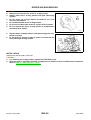
PRECAUTIONS
PRECAUTIONS
PFP:00001
Precautions for Supplemental Restraint System (SRS) “AIR BAG” and “SEAT
BELT PRE-TENSIONER”
A
AHS0001K
The Supplemental Restraint System such as “AIR BAG” and “SEAT BELT PRE-TENSIONER”, used along
with a front seat belt, helps to reduce the risk or severity of injury to the driver and front passenger for certain
types of collision. This system includes seat belt switch inputs and dual stage front air bag modules. The SRS
system uses the seat belt switches to determine the front air bag deployment, and may only deploy one front
air bag, depending on the severity of a collision and whether the front occupants are belted or unbelted.
Information necessary to service the system safely is included in the SRS and SB section of this Service Manual.
WARNING:
●
To avoid rendering the SRS inoperative, which could increase the risk of personal injury or death
in the event of a collision which would result in air bag inflation, all maintenance must be performed by an authorized NISSAN/INFINITI dealer.
●
Improper maintenance, including incorrect removal and installation of the SRS, can lead to personal injury caused by unintentional activation of the system. For removal of Spiral Cable and Air
Bag Module, see the SRS section.
●
Do not use electrical test equipment on any circuit related to the SRS unless instructed to in this
Service Manual. SRS wiring harnesses can be identified by yellow and/or orange harnesses or
harness connectors.
B
C
D
E
F
G
Precautions for SRS “AIR BAG” and “SEAT BELT PRE-TENSIONER” Service
AHS0001L
●
●
●
●
●
●
●
●
Do not use electrical test equipment to check SRS circuits unless instructed to in this Service Manual.
SRS
Before servicing the SRS, turn ignition switch OFF, disconnect both battery cables and wait at least 3 minutes.
For approximately 3 minutes after the cables are removed, it is still possible for the air bag and seat belt
I
pre-tensioner to deploy. Therefore, do not work on any SRS connectors or wires until at least 3 minutes
have passed.
Diagnosis sensor unit must always be installed with their arrow marks “⇐” pointing towards the front of the
vehicle for proper operation. Also check diagnosis sensor unit for cracks, deformities or rust before instal- J
lation and replace as required.
The spiral cable must be aligned with the neutral position since its rotations are limited. Do not attempt to
K
turn steering wheel or column after removal of steering gear.
Handle air bag module carefully. Always place driver and front passenger air bag modules with the pad
side facing upward and seat mounted front side air bag module standing with the stud bolt side facing
L
down.
Conduct self-diagnosis to check entire SRS for proper function after replacing any components.
After air bag inflates, the front instrument panel assembly should be replaced if damaged.
M
Always replace instrument panel pad following front passenger air bag deployment.
Precautions for Battery Service
AHS00099
Before disconnecting the battery, lower both the driver and passenger windows. This will prevent any interference between the window edge and the vehicle when the door is opened/closed. During normal operation, the
window slightly raises and lowers automatically to prevent any window to vehicle interference. The automatic
window function will not work with the battery disconnected.
Trouble Diagnosis Precaution
AHS0001M
When you read wiring diagrams, refer to the following:
●
GI-15, "How to Read Wiring Diagrams" in GI section
●
PG-4, "POWER SUPPLY ROUTING CIRCUIT" in PG section
When you perform trouble diagnosis, refer to the following:
●
GI-11, "HOW TO FOLLOW TEST GROUPS IN TROUBLE DIAGNOSES" in GI section
●
GI-27, "How to Perform Efficient Diagnosis for an Electrical Incident" in GI section
Check for any service bulletins before servicing the vehicle.
Revision; 2004 April
SRS-3
2003 350Z
PREPARATION
PREPARATION
Special Service Tools
PFP:00002
AHS0001N
The actual shapes of Kent-Moore tools may differ from those of special service tools illustrated here.
Tool number
(Kent-Moore No.)
Tool name
Description
HT61961000 and HT62152000
combined
(J38219)
*Special torx bit
Use for special bolts [TAMPER
RESISTANT TORX (Size T50)]
a: 3.5 (0.138) dia.
b: 8.5 - 8.6 (0.335 - 0.339) dia.
c: approx. 10 (0.39) sq.
Unit: mm (in)
S-NT361
KV99105300
(J41246)
Air bag module bracket
Anchoring air bag module
S-NT354
KV99106400
(J38381)
Deployment tool
Disposing of air bag module and front seat
belt pre-tensioner
S-NT357
(J38381-65)
Deployment tool adapter for front
passenger air bag module
Connecting between the deployment tool
and front passenger air bag module
SHIA0173E
(J38381-80)
●
Deployment tool adapter for
driver air bag module(Yellow and
orange connectors)
●
Deployment tool adapter for front
seat belt pre-tensioner(Yellow
connector)
●
Deployment tool adapter for side
curtain air bag module(Yellow
connector)
Revision; 2004 April
●
Connecting between the deployment tool
and driver air bag module
●
Connecting between the deployment tool
and front seat belt pre-tensioner
●
Connecting between the deployment tool
and side curtain air bag module
PHIA0184E
SRS-4
2003 350Z
PREPARATION
Tool number
(Kent-Moore No.)
Tool name
A
Description
B
KV99108300
(J38381-35)
Deployment tool adapter for front
side air bag module
Connecting between the deployment tool
and front side air bag module
C
ZZA1166D
D
(J-44615)
Air bag lock master key set
E
Removing and installing air bag lock
F
LRS191
Commercial Service Tools
AHS0001O
Tool name
Description
Tamper resistant torx socket
Size: T30
G
SRS
I
S-NT757
J
K
L
M
Revision; 2004 April
SRS-5
2003 350Z
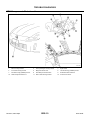
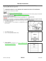
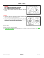
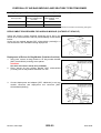
SUPPLEMENTAL RESTRAINT SYSTEM (SRS)
SUPPLEMENTAL RESTRAINT SYSTEM (SRS)
SRS Configuration
PFP:28556
AHS0001P
WHIA0042E
The air bag deploys if the diagnosis sensor unit activates while the ignition switch is in the ON or START position.
The collision modes for which supplemental restraint systems are activated are different among the SRS systems. For example, the driver air bag module and front passenger air bag module are activated in a frontal collision but not in a side collision.
SRS configurations which are activated for some collision modes are as follows;
SRS configuration
Frontal collision
Left side collision
Right side collision
Driver air bag module
×
—
—
Front passenger air bag module
×
—
—
Front LH seat belt pre-tensioner
×
—
—
Front RH seat belt pre-tensioner
×
—
—
Front LH side air bag module
—
×
—
Front RH side air bag module
—
—
×
LH side curtain air bag module
—
×
—
RH side curtain air bag module
—
—
×
Revision; 2004 April
SRS-6
2003 350Z
SUPPLEMENTAL RESTRAINT SYSTEM (SRS)
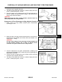
Front Seat Belt Pre-tensioner with Load Limiter
The seat belt pre-tensioner system with load limiter is installed for
both the driver's seat and the front passenger's seat. It operates
simultaneously with the SRS air bag system in the event of a frontal
collision with an impact exceeding a specified level.
When the frontal collision with an impact exceeding a specified level
occurs, seat belt slack resulting from clothing or other factors is
immediately taken up by the pre-tensioner. Vehicle passengers are
securely restrained.
When passengers in a vehicle are thrown forward in a collision and
the restraining force of the seat belt exceeds a specified level, the
load limiter permits the specified extension of the seat belt by the
twisting of the ELR shaft, and a relaxation of the chest-area seat belt
web tension while maintaining force.
AHS0001Q
A
B
C
D
SRS444
E
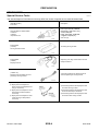
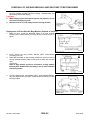
Front Side Air Bag
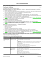
AHS0001R
Front side air bag is built-in type.
The front seatbacks with built-in type side air bag have the labels as
shown.
F
G
SRS
PHIA0158E
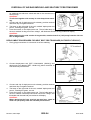
Side Curtain Air Bag
I
AHS0001S
The side curtain air bags have the labels as shown.
J
K
L
PHIA0159E
Revision; 2004 April
SRS-7
2003 350Z
M
TROUBLE DIAGNOSIS
TROUBLE DIAGNOSIS
Trouble Diagnoses Introduction
PFP:00004
AHS0001T
CAUTION:
●
Do not use electrical test equipment on any circuit related to the SRS unless instructed in this Service Manual. SRS wiring harnesses can be identified by yellow and/or orange harness connectors.
●
Do not attempt to repair, splice or modify the SRS wiring harness. If the harness is damaged,
replace it with a new one.
●
Keep ground portion clean.
DIAGNOSIS FUNCTION
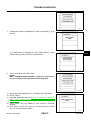
The SRS self-diagnosis results can be read by using “AIR BAG” warning lamp and/or CONSULT-II.
The User mode is exclusively prepared for the customer (driver). This mode warns the driver of a system malfunction through the operation of the “AIR BAG” warning lamp.
The Diagnosis mode allows the technician to locate and inspect the malfunctioning part.
The mode applications for the “AIR BAG” warning lamp and CONSULT-II are as follows:
User mode
Diagnosis mode
Display type
“AIR BAG” warning lamp
X
X
ON-OFF operation
CONSULT-II
—
X
Monitoring
HOW TO PERFORM TROUBLE DIAGNOSES FOR QUICK AND ACCURATE REPAIR
A good understanding of the malfunction conditions can make troubleshooting faster and more accurate.
In general, each customer feels differently about a malfunction. It is important to fully understand the symptoms or conditions for a customer complaint.
Information from Customer
WHAT..... Vehicle model
WHEN..... Date, Frequencies
WHERE..... Road conditions
HOW..... Operating conditions, Symptoms
Preliminary Check
Check that the following parts are in good order.
●
Battery (Refer to SC-4, "How to Handle Battery" .)
●
Fuse (Refer to SRS-12, "Wiring Diagram-SRS-" .)
●
System component-to-harness connections
Revision; 2004 April
SRS-8
2003 350Z
TROUBLE DIAGNOSIS
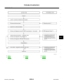
WORK FLOW
A
B
C
D
E
F
G
SRS
I
J
K
L
PHIA0217E
*1: SRS-8
*2: SRS-18
*3: SRS-26
*4: SRS-26
*5
*6
Revision; 2004 April
SRS-23
SRS-9
M
SRS-30
2003 350Z
TROUBLE DIAGNOSIS
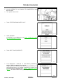
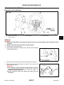
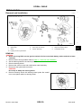
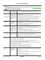
SRS Components Parts Location
AHS0001U
PHIA0160E
1.
Driver air bag module
2.
Front passenger air bag module
4.
Front side air bag module
5.
Diagnosis sensor unit
6.
LH side air bag (satellite) sensor
7.
RH side air bag (satellite) sensor
8.
Seat belt pre-tensioner RH
9.
Seat belt buckle switches
10. Seat belt pre-tensioner LH
Revision; 2004 April
11. Side curtain air bag module
SRS-10
3.
Spiral cable
12. Crash zone sensor
2003 350Z
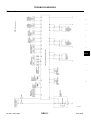
TROUBLE DIAGNOSIS
Schematic
AHS0001V
A
B
C
D
E
F
G
SRS
I
J
K
L
M
THWT0023E
Revision; 2004 April
SRS-11
2003 350Z
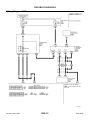
TROUBLE DIAGNOSIS
Wiring Diagram-SRS-
AHS0001W
THWT0024E
Revision; 2004 April
SRS-12
2003 350Z
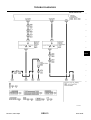
TROUBLE DIAGNOSIS
A
B
C
D
E
F
G
SRS
I
J
K
L
M
THWT0025E
Revision; 2004 April
SRS-13
2003 350Z
TROUBLE DIAGNOSIS
THWT0026E
Revision; 2004 April
SRS-14
2003 350Z
TROUBLE DIAGNOSIS
A
B
C
D
E
F
G
SRS
I
J
K
L
M
THWT0027E
Revision; 2004 April
SRS-15
2003 350Z
TROUBLE DIAGNOSIS
CONSULT-II Function
AHS0001X
DIAGNOSIS MODE FOR CONSULT-II
●
●
●
●
“SELF-DIAG [CURRENT]”
A current Self-diagnosis result (also indicated by the number of warning lamp flashes in the Diagnosis
mode) is displayed on the CONSULT-II screen in real time. This refers to a malfunctioning part requiring
repairs.
“SELF-DIAG [PAST]”
Diagnosis results previously stored in the memory are displayed on the CONSULT-II screen. The stored
results are not erased until memory erasing is executed.
“TROUBLE DIAG RECORD”
With TROUBLE DIAG RECORD, diagnosis results previously erased by a reset operation can be displayed on the CONSULT-II screen.
“ECU DISCRIMINATED NO.”
The diagnosis sensor unit for each vehicle model is assigned
with its own, individual classification number. This number will
be displayed on the CONSULT-II screen, as shown. When
replacing the diagnosis sensor unit, refer to the part number for
the compatibility. After installation, replacement with a correct
unit can be checked by confirming this classification number on
the CONSULT-II screen.
After repair, make sure the discriminated number shown in figure at right and the discriminated number of diagnosis sensor
unit installed to vehicle are same.
PHIA0218E
Discriminated No.
With driver air bag module and passenger air bag module
With side air bag module and side
curtain air bag module
FH51H
×
—
FH53H
×
×
HOW TO CHANGE SELF-DIAGNOSIS MODE WITH CONSULT-II
From User Mode to Diagnosis Mode
After selecting “AIR BAG” on the “SELECT SYSTEM” screen, User mode automatically changes to Diagnosis
mode.
SRS803
Revision; 2004 April
SRS-16
2003 350Z
TROUBLE DIAGNOSIS
From Diagnosis Mode to User Mode
To return to User mode from Diagnosis mode, touch “BACK” key of CONSULT-II until “SELECT SYSTEM”
appears, Diagnosis mode automatically changes to User mode.
A
B
C
D
E
SRS804
HOW TO ERASE SELF-DIAGNOSIS RESULTS
●
●
●
“SELF-DIAG [CURRENT]”
F
A current Self-diagnosis result is displayed on the CONSULT-II screen in real time.
After the malfunction is repaired completely, no malfunction is detected on “SELF-DIAG [CURRENT]”.
“SELF-DIAG [PAST]”
G
Return to the “SELF-DIAG [CURRENT]” CONSULT-II screen by touching “BACK” key of CONSULT-II and
select “SELF-DIAG [CURRENT]” in SELECT DIAG MODE. Touch “ERASE” in “SELF-DIAG [CURRENT]”
mode.
SRS
NOTE:
If the memory of the malfunction in “SELF-DIAG [PAST]” is not erased, the User mode shows the
system malfunction by the operation of the warning lamp even if the malfunction is repaired completely.
I
“TROUBLE DIAG RECORD”
The memory of “TROUBLE DIAG RECORD” cannot be erased.
J
K
L
SRS701
Self-diagnosis Function (Without CONSULT-II)
●
●
AHS0001Y
The reading of these results is accomplished using one of two modes — “User mode” and “Diagnosis
mode”.
After a malfunction is repaired, turn the ignition switch OFF for at least one second, then back ON. Diagnosis mode returns to the User mode. At that time, the self-diagnostic result is cleared.
Revision; 2004 April
SRS-17
2003 350Z
M
TROUBLE DIAGNOSIS
HOW TO CHANGE SELF-DIAGNOSIS MODE
PHIA0531E
HOW TO ERASE SELF-DIAGNOSIS RESULTS
After a malfunction is repaired, turn the ignition switch OFF for at least one second, then back ON. Diagnosis
mode returns to the User mode. At that time, the self-diagnostic result is cleared.
SRS Operation Check
AHS0001Z
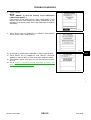
DIAGNOSTIC PROCEDURE 1
Checking Air Bag Operation by Using “AIR BAG” Warning Lamp-User Mode
1.
2.
Turn the ignition switch from OFF to ON, and check that the air bag warning lamp blinks.
Compare the SRS air bag warning lamp blinking pattern with the
examples.
BF-1845D
Revision; 2004 April
SRS-18
2003 350Z
TROUBLE DIAGNOSIS
Warning lamp examples
“AIR BAG” warning lamp operation-User mode-
SRS condition
A
Reference item
B
●
No malfunction is detected.
●
No further action is necessary.
C
—
D
SHIA0011E
E
F
●
The system is malfunctioning and
need to be repaired as indicated.
Go to SRS-20, "Diagnostic procedure 2" or SRS-30, "Diagnostic procedure 6" .
G
SRS
SHIA0012E
●
Air bag is deployed.
●
Seat belt pre-tensioner is deployed.
Go to SRS-56, "COLLISION DIAGNOSIS" .
I
●
Diagnosis sensor unit is malfunctioning.
●
Air bag power supply circuit is malfunctioning.
●
SRS air bag warning lamp circuit is
malfunctioning.
Go to SRS-35, "Trouble Diagnoses:
“AIR BAG” Warning Lamp Does Not
Turn Off" .
J
K
SHIA0013E
L
●
●
Diagnosis sensor unit is malfunctioning.
Air bag warning lamp circuit is malfunctioning.
Go to SRS-36, "Trouble Diagnoses:
“AIR BAG” Warning Lamp Does Not
Turn On" .
SHIA0014E
Revision; 2004 April
SRS-19
2003 350Z
M
TROUBLE DIAGNOSIS
Trouble Diagnoses with CONSULT-II
AHS0009A
DIAGNOSTIC PROCEDURE 2
CAUTION:
If CONSULT-II is used with no connection of CONSULT-II CONVERTER, malfunctions might be
detected in self-diagnosis depending on control unit which carry out CAN communication.
1. Turn ignition switch OFF.
2. Connect CONSULT-II and CONSULT-II CONVERTER to the
data link connector.
PBIB1069E
3.
4.
Turn ignition switch ON.
Touch “START(NISSAN BASED VHCL)”.
PHIA0157E
5.
Touch “AIR BAG”.
If "AIR BAG" is not indicated, go to GI-39, "CONSULT-II Data
Link Connector (DLC) Circuit" .
SRS771
6.
Touch "SELF-DIAG [CURRENT]".
SRS697
Revision; 2004 April
SRS-20
2003 350Z
TROUBLE DIAGNOSIS
7.
Diagnostic code is displayed on "SELF-DIAG [CURRENT]".
A
B
C
SHIA0203E
D
If no malfunction is detected on "SELF-DIAG [CURRENT]" even
though malfunction is detected in "SRS Operation Check", check the
battery voltage. If the battery voltage is less than 9V, charge or
replace the battery. SRS-23, "DIAGNOSTIC PROCEDURE 3" . If the
battery voltage is OK, go to SRS-26, "DIAGNOSTIC PROCEDURE
4 (CONTINUED FROM DIAGNOSTIC PROCEDURE 2)" diagnose
the following cases:
●
Self-diagnostic result "SELF-DIAG [PAST]" (previously stored in
the memory) might not be erased after repair.
●
The SRS system malfunctions intermittently.
E
F
G
SRS701
CONSULT-II Diagnostic Code Chart ("SELF-DIAG [CURRENT]")
Diagnostic item
NO DTC IS
DETECTED.
Explanation
When malfunction is
indicated by the “AIR
BAG” warning lamp in
User mode.
●
Low battery voltage (Less than 9V)
●
Go to SRS-23, "DIAGNOSTIC PROCEDURE 3" after charging the battery.
I
●
Self-diagnostic result “SELF-DIAG
[PAST]” (previously stored in the
memory) might not be erased after
repair.
●
Go to SRS-26, "DIAGNOSTIC PROCEDURE 4 (CONTINUED FROM
DIAGNOSTIC PROCEDURE 2)" .
J
●
●
Intermittent malfunction has been
detected in the past.
Go to SRS-26, "DIAGNOSTIC PROCEDURE 5" .
●
No malfunction is detected.
DRIVER AIRBAG
MODULE
[OPEN]
●
Driver air bag module circuit is open (including the spiral cable).
DRIVER AIRBAG
MODULE
[VB-SHORT]
●
Driver air bag module circuit is shorted to a power supply circuit
(including the spiral cable).
DRIVER AIRBAG
MODULE
[GND-SHORT]
●
DRIVER AIRBAG
MODULE
[SHORT]
●
Revision; 2004 April
SRS
Repair order
“Recheck SRS at each replacement”
K
—
Driver air bag module circuit is shorted to ground (including the
spiral cable).
1. Visually check the wiring harness
connection.
2. Replace the harness if it has visible
damage.
3. Replace driver air bag module.
(Before disposal, it must be
deployed.)
4. Replace the spiral cable.
5. Replace the diagnosis sensor unit.
Driver air bag module circuit is shorted between lines.
SRS-21
6. Replace the related harness.
2003 350Z
L
M
TROUBLE DIAGNOSIS
Diagnostic item
Explanation
Repair order
“Recheck SRS at each replacement”
ASSIST A/B MODULE
[VB-SHORT]
●
Front passenger air bag module circuit is shorted to a power
supply circuit.
1. Visually check the wiring harness
connection.
ASSIST A/B MODULE
[OPEN]
●
Front passenger air bag module circuit is open.
2. Replace the harness if it has visible
damage.
ASSIST A/B MODULE
[GND-SHORT]
●
Front passenger air bag module circuit is shorted to ground.
ASSIST A/B MODULE
[SHORT]
●
Front passenger air bag module circuit is shorted between lines.
3. Replace front passenger air bag
module. (Before disposal, it must be
deployed.)
4. Replace the diagnosis sensor unit.
5. Replace the related harness.
CRASH ZONE SEN
[UNIT FAIL]
CRASH ZONE SEN
[COMM FAIL]
CRASH ZONE SEN
[UNMATCH]
●
Crash zone sensor
1. Visually check the wiring harness
connection.
2. Replace the harness if it has visible
damage.
3. Replace the crash zone sensor.
4. Replace the diagnosis sensor unit.
5. Replace the related harness.
SIDE MODULE LH
[OPEN]
●
Front LH side air bag module circuit is open.
1. Visually check the wiring harness
connection.
SIDE MODULE LH
[VB-SHORT]
●
Front LH side air bag module circuit is shorted to a power supply circuit.
2. Replace the harness if it has visible
damage.
SIDE MODULE LH
[GND-SHORT]
●
Front LH side air bag module circuit is shorted to ground.
SIDE MODULE LH
[SHORT]
●
Front LH side air bag module circuit is shorted between lines.
3. Replace front LH setback assembly
(front LH side air bag module).
(Before disposal, it must be
deployed.)
4. Replace the diagnosis sensor unit.
5. Replace the related harness.
SIDE MODULE RH
[OPEN]
●
Front RH side air bag module circuit is open.
1. Visually check the wiring harness
connection.
SIDE MODULE RH
[VB-SHORT]
●
Front RH side air bag module circuit is shorted to some power
supply circuit.
2. Replace the harness if it has visible
damage.
SIDE MODULE RH
[GND-SHORT]
●
Front RH side air bag module circuit is shorted to ground.
SIDE MODULE RH
[SHORT]
●
Front RH side air bag module circuit is shorted between lines.
3. Replace front RH setback assembly
(front RH side air bag module).
(Before disposal, it must be
deployed.)
4. Replace the diagnosis sensor unit.
5. Replace the related harness.
SATELLITE SENS LH
[UNIT FAIL]
SATELLITE SENS LH
[COMM FAIL]
SATELLITE SENS LH
[UNMATCH]
●
LH side air bag (Satellite) sensor
1. Visually check the wiring harness
connection.
2. Replace the harness if it has visible
damage.
3. Replace the LH side air bag (Satellite) sensor.
4. Replace the diagnosis sensor unit.
5. Replace the related harness.
SATELLITE SENS RH
[UNIT FAIL]
SATELLITE SENS RH
[COMM FAIL]
SATELLITE SENS RH
[UNMATCH]
●
RH side air bag (Satellite) sensor
1. Visually check the wiring harness
connection.
2. Replace the harness if it has visible
damage.
3. Replace the RH side air bag (Satellite) sensor.
4. Replace the diagnosis sensor unit.
5. Replace the related harness.
Revision; 2004 April
SRS-22
2003 350Z
TROUBLE DIAGNOSIS
Diagnostic item
Explanation
Repair order
“Recheck SRS at each replacement”
PRE-TEN FRONT LH
[OPEN]
●
Front LH pre-tensioner is circuit is open.
1. Visually check the wiring harness
connections.
PRE-TEN FRONT LH
[VB-SHORT]
●
Front LH pre-tensioner circuit is shorted to a power supply circuit.
2. Replace the harness if it has visible
damage.
PRE-TEN FRONT LH
[GND-SHORT]
●
Front LH pre-tensioner circuit is shorted to ground.
PRE-TEN FRONT LH
[SHORT]
●
Front LH pre-tensioner circuit is shorted between lines.
3. Replace front LH seat belt.
(Before disposal, it must be activated.)
A
B
C
4. Replace the diagnosis sensor unit.
5. Replace the related harness.
PRE-TEN FRONT RH
[OPEN]
●
Front RH pre-tensioner circuit is shorted to a power supply circuit.
1. Visually check the wiring harness
connections.
PRE-TEN FRONT RH
[VB-SHORT]
●
Front RH pre-tensioner is shorted to a power supply circuit.
2. Replace the harness if it has visible
damage.
PRE-TEN FRONT RH
[GND-SHORT]
●
Front RH pre-tensioner circuit is shorted to ground.
PRE-TEN FRONT RH
[SHORT]
●
Front RH pre-tensioner circuit is shorted between lines.
3. Replace front RH seat belt.
(Before disposal, it must be activated.)
D
E
F
4. Replace the diagnosis sensor unit.
5. Replace the related harness.
CURTAIN MODULE LH
[OPEN]
●
LH side curtain air bag module circuit is open.
1. Visually check the wiring harness
connection.
CURTAIN MODULE LH
[VB-SHORT]
●
LH side curtain air bag module circuit is shorted to some power
supply circuits.
2. Replace the harness if it has visible
damage.
CURTAIN MODULE LH
[GND-SHORT]
●
LH side curtain air bag module circuit is shorted to ground.
CURTAIN MODULE LH
[SHORT]
●
LH side curtain air bag module circuit is shorted between lines.
3. Replace LH side curtain air bag
module.
(Before disposal, it must be
deployed.)
G
SRS
I
4. Replace the diagnosis sensor unit.
5. Replace the related harness.
CURTAIN MODULE RH
[OPEN]
●
RH side curtain air bag module circuit is open.
1. Visually check the wiring harness
connection.
CURTAIN MODULE RH
[VB-SHORT]
●
RH side curtain air bag module circuit is shorted to a power supply circuit.
2. Replace the harness if it has visible
damage.
CURTAIN MODULE RH
[GND-SHORT]
●
RH side curtain air bag module circuit is shorted to ground.
CURTAIN MODULE RH
[SHORT]
●
3. Replace RH side curtain air bag
module.
(Before disposal, it must be
deployed.)
RH side curtain air bag module circuit is shorted between lines.
4. Replace the diagnosis sensor unit.
5. Replace the related harness.
CONTROL UNIT
●
Diagnosis sensor unit is malfunctioning.
1. Visually check the wiring harness
connection.
2. Replace the diagnosis sensor unit.
NOTE:
●
Follow the procedures in numerical order when repairing malfunctioning parts. Confirm whether malfunction is eliminated using air bag warning lamp or CONSULT-II each time repair is finished. If malfunction is
still observed, proceed to the next step. When malfunction is eliminated, further repair work is not
required.
DIAGNOSTIC PROCEDURE 3
Final checking after repairing SRS by using CONSULT-II — Diagnosis mode
CAUTION:
If CONSULT-II is used with no connection of CONSULT-II CONVERTER, malfunctions might be
detected in self-diagnosis depending on control unit which carry out CAN communication.
Revision; 2004 April
SRS-23
2003 350Z
J
K
L
M
TROUBLE DIAGNOSIS
1.
2.
3.
After repairing SRS, connect both battery cables.
Connect CONSULT-II and CONSULT-II CONVERTER to data
link connector.
Turn ignition switch “ON”.
PBIB1069E
4.
Touch “START(NISSAN BASED VHCL)”.
PHIA0157E
5.
Touch “AIR BAG”.
If "AIR BAG" is not indicated, go to GI-39, "CONSULT-II Data
Link Connector (DLC) Circuit" .
SRS771
6.
Touch “SELF-DIAG [CURRENT]”.
SRS697
7.
If no malfunction is detected on “SELF-DIAG [CURRENT]”,
repair of SRS is completed. Go to step 8.
If any malfunction is detected on “SELF-DIAG [CURRENT]”, the
malfunctioning part is not repaired completely or another malfunctioning part is detected. Go to SRS-20, "Diagnostic procedure 2" , and repair malfunctioning part completely.
SRS701
Revision; 2004 April
SRS-24
2003 350Z
TROUBLE DIAGNOSIS
8.
Touch “ERASE”.
NOTE:
Touch “ERASE” to clear the memory of the malfunction
(“SELF-DIAG [PAST]”).
If the memory of the malfunction in “SELF-DIAG [PAST]” is not
erased, the User mode shows the system malfunction by the
operation of the warning lamp even if the malfunction is repaired
completely.
A
B
C
SRS773
9.
Touch “BACK” key of CONSULT-II to “SELECT DIAG MODE”
screen. Touch “SELF-DIAG [PAST]”.
D
E
F
G
SRS697
SRS
10. Check that no malfunction is detected on “SELF-DIAG [PAST]”.
11. Touch “BACK” key of CONSULT-II until “SELECT SYSTEM”
appears in order to return to User mode from Diagnosis mode.
12. Turn ignition switch OFF then turn off and disconnect CONSULT-II.
13. Go to SRS-18, "Checking Air Bag Operation by Using “AIR
BAG” Warning Lamp-User Mode" .
I
J
SRS702
K
L
M
Revision; 2004 April
SRS-25
2003 350Z
TROUBLE DIAGNOSIS
DIAGNOSTIC PROCEDURE 4 (CONTINUED FROM DIAGNOSTIC PROCEDURE 2)
Inspecting SRS malfunctioning record
1. CONSIDER POSSIBILITY OF NOT ERASING SELF-DIAGNOSTIC RESULT AFTER REPAIRING
Is it the first time for maintenance of SRS?
Yes or No
Yes
>> Go to SRS-20, "Diagnostic procedure 2" .
No
>> Self-diagnostic result “SELF-DIAG [PAST]” (previously stored in the memory) might not be erased
after repair. Go to SRS-23, "DIAGNOSTIC PROCEDURE 3" .
DIAGNOSTIC PROCEDURE 5
Inspecting SRS intermittent malfunction by using CONSULT-II — Diagnosis mode
CAUTION:
If CONSULT-II is used with no connection of CONSULT-II CONVERTER, malfunction might be detected
in self-diagnosis depending on control unit which carry out CAN communication.
1. Turn ignition switch OFF.
2. Connect CONSULT-II and CONSULT-II CONVERTER to data
link connector.
PBIB1069E
3.
4.
Turn ignition switch ON.
Touch “START(NISSAN BASED VHCL)”.
PHIA0157E
5.
Touch “AIR BAG”.
If "AIR BAG" is not indicated, go to GI-39, "CONSULT-II Data
Link Connector (DLC) Circuit" .
SRS771
Revision; 2004 April
SRS-26
2003 350Z
TROUBLE DIAGNOSIS
6.
Touch “SELF-DIAG [PAST]”.
A
B
C
SRS697
D
7.
If diagnostic codes are displayed on “SELF-DIAG [PAST]”, go to
step 10.
E
F
G
SRS700
If no malfunction is detected on “SELF-DIAG [PAST]”, touch
“BACK” and go back to “SELECT DIAG MODE”.
SRS
I
J
SRS702
8.
Touch “TROUBLE DIAG RECORD”.
NOTE:
With “TROUBLE DIAG RECORD”, diagnosis results previously erased by a reset operation can be displayed.
K
L
M
SRS697
9. Diagnostic code is displayed on “TROUBLE DIAG RECORD”.
10. Touch “PRINT”.
11. Compare diagnostic codes to SRS-28, "CONSULT-II Diagnostic
Code Chart ("SELF-DIAG [PAST]" or TROUBLE DIAG
RECORD")" .
12. Touch “BACK” key of CONSULT-II until “SELECT SYSTEM”
appears.
13. Turn ignition switch OFF, then turn off and disconnect CONSULT-II, and both battery cables.
SHIA0182E
Revision; 2004 April
SRS-27
2003 350Z
TROUBLE DIAGNOSIS
14. Repair the system as outlined by the “Repair order” in “Intermittent Malfunction Diagnostic Code Chart”,
that corresponds to the self-diagnostic result. For replacement procedure of component parts, refer to the
Removal and Installation procedure for the appropriate component.
15. Go to SRS-23, "DIAGNOSTIC PROCEDURE 3" , for final checking.
CONSULT-II Diagnostic Code Chart ("SELF-DIAG [PAST]" or TROUBLE DIAG RECORD")
Diagnostic item
NO DTC IS
DETECTED.
Explanation
When malfunction is
indicated by the “AIR
BAG” warning lamp in
User mode.
●
Low battery voltage (Less than 9V)
Repair order
“Recheck SRS at each replacement”
●
Go to SRS-23, "DIAGNOSTIC PROCEDURE 3" .
Go to SRS-23, "DIAGNOSTIC PROCEDURE 3" .
●
No malfunction is detected.
●
DRIVER AIRBAG
MODULE
[OPEN]
●
Driver air bag module circuit is open (including the spiral cable).
1. Visually check the wiring harness
connection.
DRIVER AIRBAG
MODULE
[VB-SHORT]
●
Driver air bag module circuit is shorted to a power supply circuit
(including the spiral cable).
DRIVER AIRBAG
MODULE
[GND-SHORT]
●
Driver air bag module circuit is shorted to ground (including the
spiral cable).
DRIVER AIRBAG
MODULE
[SHORT]
●
Driver air bag module circuit is shorted between lines.
ASSIST A/B MODULE
[OPEN]
●
Front passenger air bag module circuit is open.
1. Visually check the wiring harness
connection.
ASSIST A/B MODULE
[VB-SHORT]
●
Front passenger air bag module circuit is shorted to a power
supply circuit.
2. Replace the harness if it has visible
damage.
ASSIST A/B MODULE
[GND-SHORT]
●
Front passenger air bag module circuit is shorted to ground.
ASSIST A/B MODULE
[SHORT]
●
Front passenger air bag module circuit is shorted between lines.
3. If the harness check result is OK,
replace the diagnosis sensor unit
and front passenger air bag module
(Before disposal, it must be
deployed.).
CRASH ZONE SEN
[UNIT FAIL]
CRASH ZONE SEN
[COMM FAIL]
CRASH ZONE SEN
[UNMATCH]
●
Crash zone sensor
SIDE MODULE LH
[OPEN]
●
Front LH side air bag module circuit is open.
1. Visually check the wiring harness
connection.
SIDE MODULE LH
[VB-SHORT]
●
Front LH side air bag module circuit is shorted to a power supply circuit.
2. Replace the harness if it has visible
damage.
SIDE MODULE LH
[GND-SHORT]
●
Front LH side air bag module circuit is shorted to ground.
SIDE MODULE LH
[SHORT]
●
Front LH side air bag module circuit is shorted between lines.
3. If the harness check result is OK,
replace the diagnosis sensor unit
and LH side air bag module. (Before
disposal, it must be deployed.).
Revision; 2004 April
2. Replace the harness if it has visible
damage.
3. If the harness check result is OK,
replace driver air bag module
(Before disposal, it must be
deployed.), diagnosis sensor unit
and spiral cable.
1. Visually check the wiring harness
connection.
2. Replace the harness if it has visible
damage.
3. If the harness check result is OK,
replace crash zone sensor and diagnosis sensor unit.
SRS-28
2003 350Z
TROUBLE DIAGNOSIS
Diagnostic item
Explanation
Repair order
“Recheck SRS at each replacement”
SIDE MODULE RH
[OPEN]
●
Front RH side air bag module circuit is open.
1. Visually check the wiring harness
connection.
SIDE MODULE RH
[VB-SHORT]
●
Front RH side air bag module circuit is shorted to a power supply circuit.
2. Replace the harness if it has visible
damage.
SIDE MODULE RH
[GND-SHORT]
●
Front RH side air bag module circuit is shorted to ground.
SIDE MODULE RH
[SHORT]
●
Front RH side air bag module circuit is shorted between lines.
3. If the harness check result is OK,
replace the diagnosis sensor unit
and RH side air bag module
(Before disposal, it must be
deployed.)
SATELLITE SENS LH
[UNIT FAIL]
SATELLITE SENS LH
[COMM FAIL]
SATELLITE SENS LH
[UNMATCH]
●
LH side air bag (Satellite) sensor
1. Visually check the wiring harness
connection.
2. Replace the harness if it has visible
damage.
3. If the harness check result is OK,
replace the diagnosis sensor unit
and LH side air bag (Satellite) sensor.
RH side air bag (Satellite) sensor
1. Visually check the wiring harness
connection.
A
B
C
D
E
F
SATELLITE SENS RH
[UNIT FAIL]
SATELLITE SENS RH
[COMM FAIL]
SATELLITE SENS RH
[UNMATCH]
●
PRE-TEN FRONT LH
[OPEN]
●
Front LH pre-tensioner circuit is open.
1. Visually check the wiring harness
connections.
PRE-TEN FRONT LH
[VB-SHORT]
●
Front LH pre-tensioner circuit is shorted to a power supply circuit.
2. Replace the harness if it has visible
damage.
J
PRE-TEN FRONT LH
[GND-SHORT]
●
Front LH pre-tensioner circuit is shorted to ground.
PRE-TEN FRONT LH
[SHORT]
●
Front LH pre-tensioner circuit is shorted between lines.
3. If the harness check result is OK,
replace the diagnosis sensor unit
and front LH seat belt
(Before disposal, it must be activated.)
K
PRE-TEN FRONT RH
[OPEN]
●
Front RH pre-tensioner circuit is open.
1. Visually check the wiring harness
connections.
L
PRE-TEN FRONT RH
[VB-SHORT]
●
Front RH pre-tensioner is shorted to a power supply circuit.
2. Replace the harness if it has visible
damage.
PRE-TEN FRONT RH
[GND-SHORT]
●
Front RH pre-tensioner is shorted to ground.
PRE-TEN FRONT RH
[SHORT]
●
Front RH pre-tensioner circuit is shorted between lines.
3. If the harness check result is OK,
replace the diagnosis sensor unit
and front RH seat belt
(Before disposal, it must be activated.)
CURTAIN MODULE LH
[OPEN]
●
LH side curtain air bag module circuit is open.
1. Visually check the wiring harness
connection.
CURTAIN MODULE LH
[VB-SHORT]
●
LH side curtain air bag module circuit is shorted to a power supply circuits.
2. Replace the harness if it has visible
damage.
CURTAIN MODULE LH
[GND-SHORT]
●
LH side curtain air bag module circuit is shorted to ground.
3. If the harness check result is OK,
replace the diagnosis sensor unit
and LH side curtain air bag module.
(Before disposal, it must be
deployed.)
Revision; 2004 April
G
2. Replace the harness if it has visible
damage.
3. If the harness check result is OK,
replace the diagnosis sensor unit
and RH side air bag (Satellite) sensor.
SRS-29
2003 350Z
SRS
I
M
TROUBLE DIAGNOSIS
Diagnostic item
Explanation
Repair order
“Recheck SRS at each replacement”
CURTAIN MODULE RH
[OPEN]
●
RH side curtain air bag module circuit is open.
1. Visually check the wiring harness
connection.
CURTAIN MODULE RH
[VB-SHORT]
●
RH side curtain air bag module circuit is shorted to a power supply circuit.
2. Replace the harness if it has visible
damage.
CURTAIN MODULE RH
[GND-SHORT]
●
The RH side curtain air bag module circuit is shorted to ground.
CURTAIN MODULE RH
[SHORT]
●
RH side curtain air bag module circuit is shorted between lines.
3. If the harness check result is OK,
replace the diagnosis sensor unit
and RH side curtain air bag module.
(Before disposal, it must be
deployed.)
CONTROL UNIT
●
Diagnosis sensor unit is malfunctioning.
1. Visually check the wiring harness
connection.
2. Replace the diagnosis sensor unit.
Trouble diagnoses without CONSULT-II.
AHS0009B
DIAGNOSTIC PROCEDURE 6
Inspecting SRS malfunctioning parts by using "AIR BAG" warning lamp—Diagnosis mode
NOTE:
SRS will not enter Diagnosis mode if no malfunction is detected in User mode.
1. Turn ignition switch ON.
2. After “AIR BAG” warning lamp lights for 7 seconds, turn ignition switch OFF within 1 second.
3. Wait more than 3 seconds.
4. Repeat the steps 1 to 3 two times.
5. Turn ignition switch ON.
SRS is now in Diagnosis mode.
"AIR BAG" warning lamp operates in Diagnosis mode as follows:
Revision; 2004 April
SRS-30
2003 350Z
TROUBLE DIAGNOSIS
WARNING LAMP FLASH CODE CHART
A
B
C
D
PHIA0532E
E
F
G
PHIA0185E
SRS
I
J
K
SHIA0028E
L
M
SHIA0029E
Revision; 2004 April
SRS-31
2003 350Z
TROUBLE DIAGNOSIS
SHIA0083E
SHIA0030E
SHIA0031E
SHIA0032E
Revision; 2004 April
SRS-32
2003 350Z
TROUBLE DIAGNOSIS
A
B
C
SHIA0033E
D
E
F
G
SHIA0034E
SRS
I
J
K
SHIA0035E
L
M
SHIA0084E
Revision; 2004 April
SRS-33
2003 350Z
TROUBLE DIAGNOSIS
SHIA0086E
Revision; 2004 April
SRS-34
2003 350Z
TROUBLE DIAGNOSIS
Trouble Diagnoses: “AIR BAG” Warning Lamp Does Not Turn Off
AHS0009C
A
DIAGNOSTIC PROCEDURE 7
1. SEE THE DEPLOYMENT OF AIR BAG MODULE
B
Is air bag module deployed?
Yes or No
Yes
>> Refer to SRS-56, "COLLISION DIAGNOSIS" .
No
>> GO TO 2.
C
2. CHECK THE AIR BAG FUSE
D
Check the fuse (No.13) [located in the fuse block (J/B)].
Refer to PG-4, "POWER SUPPLY ROUTING CIRCUIT" .
OK or NG
OK
>> GO TO 4.
NG
>> GO TO 3.
E
3. CHECK AIR BAG FUSE AGAIN
F
Replace “AIR BAG” fuse and turn ignition switch ON.
Does the “AIR BAG” fuse blow again?
Yes
>> Repair main harness.
No
>> INSPECTION END.
G
SRS
4. CHECK DIAGNOSIS SENSOR UNIT
I
Connect CONSULT-II and touch “START”.
●
Is “AIR BAG” displayed on CONSULT-II?
Yes or No
Yes
>> GO TO 5.
No
>> Visually check the wiring harness connection of diagnosis sensor unit. If the harness connection check result is
OK, replace diagnosis sensor unit.
J
K
L
SRS771
5. CHECK HARNESS CONNECTION
M
Is harness connection between warning lamp and diagnosis sensor unit OK?
OK or NG
OK
>> Replace diagnosis sensor unit.
NG
>> Connect “AIR BAG” warning lamp and diagnosis sensor unit connector properly. If “AIR BAG”
warning lamp still does not go off, replace harness.
Revision; 2004 April
SRS-35
2003 350Z
TROUBLE DIAGNOSIS
Trouble Diagnoses: “AIR BAG” Warning Lamp Does Not Turn On
AHS0009D
DIAGNOSTIC PROCEDURE 8
1. CHECK “METER” FUSE
Check the 10A meter fuse 14 [located in the fuse block (J/B)].
Refer to PG-4, "POWER SUPPLY ROUTING CIRCUIT" .
OK or NG
OK
>> GO TO 3.
NG
>> GO TO 2.
2. CHECK “METER” FUSE AGAIN
Replace 10A meter fuse (No.14) [located in the fuse block (J/B)] and turn ignition switch ON.
Does the meter fuse blow again?
Yes
>> Repair the related harness.
No
>> INSPECTION END.
3. CHECK HARNESS CONNECTION BETWEEN DIAGNOSIS SENSOR UNIT AND COMBINATION
METER
Disconnect diagnosis sensor unit connector and turn ignition switch ON.
●
Does “AIR BAG” warning lamp turn on?
Yes or No
Yes
>> Replace diagnosis sensor unit.
No
>> Check the ground circuit of “AIR BAG” warning lamp.
Revision; 2004 April
SRS-36
2003 350Z
DRIVER AIR BAG MODULE
DRIVER AIR BAG MODULE
Removal and Installation
PFP:K8510
A
AHS000O2
B
C
D
E
F
PHIA0715E
1.
Driver air bag module
4.
TORX bolt (T30)
2.
Side lid (RH/LH)
3.
G
Steering wheel
SRS
REMOVAL
CAUTION:
●
Before servicing SRS, turn the ignition switch off, disconnect both battery cables and wait at least
3 minutes.
●
Always work from the side of driver air bag module.
1. Remove the side lids (RH/LH).
2. Using Tamper resistant TORX bit (T30), remove the TORX bolts
(T30) at right and left.
I
J
K
L
M
PHIA0714E
3.
4.
Disconnect the steering wheel switch sub-harness connector.
Disconnect the air bag harness connector, and remove the
driver air bag module.
CAUTION:
● For installing / removing driver air bag module connector,
insert thin screwdriver wrapped in tape into notch, lift
lock and remove connector.
● Install connector with lock raised, and push lock into
connector.
PHIA0308E
Revision; 2004 April
SRS-37
2003 350Z
DRIVER AIR BAG MODULE
CAUTION:
●
Always work from the side of driver air bag module.
●
Always place driver air bag module with pad side facing
upward.
●
Do not insert any foreign objects (screwdriver, etc.) into
driver air bag module.
●
Do not disassemble driver air bag module.
●
Do not use old bolts after removal; replace with new bolts.
●
Do not expose the driver air bag module to temperatures
exceeding 90°C (194°F).
PHIA0164E
●
●
Replace driver air bag module if it has been dropped or sustained an impact.
Do not allow oil, grease or water to come in contact with the
front passenger air bag module.
SBF814E
INSTALLATION
Install in the reverse order of removal.
CAUTION:
●
For installing the air bag module, tighten the TORX bolts (T30).
●
After the work is completed, perform self-diagnosis to make sure that no malfunction is detected.
Refer to SRS-18, "SRS Operation Check" .
Revision; 2004 April
SRS-38
2003 350Z
SPIRAL CABLE
SPIRAL CABLE
Removal and Installation
PFP:25554
A
AHS00025
B
C
D
E
F
G
PHIA0713E
1.
Steering wheel
2.
Nut
3.
Driver air bag module connector
4.
Spiral cable
5.
Scerw (Do not remove)
6.
Wiper and washer switch
7.
Screw
8.
Column assembly
9.
Combination meter
SRS
10. Lighting and turn signal switch
I
REMOVAL
CAUTION:
●
Before servicing SRS, turn the ignition switch off, disconnect both battery cables and wait at least
3 minutes.
1. Remove driver air bag module. Refer to SRS-37, "Removal and Installation" .
2. Set the steering wheel in the neutral position.
3. Remove steering wheel.
4. Remove the column cover and combination meter assembly.
5. Disconnect the spiral cable connector.
CAUTION:
Do not tap or bump the steering wheel.
6. Remove steering wheel with steering wheel puller. Be careful
not to over-tighten puller on steering wheel.
PHIA0100E
Revision; 2004 April
SRS-39
2003 350Z
J
K
L
M
SPIRAL CABLE
7.
8.
Remove the spiral cable fixing screws, remove the spiral cable.
CAUTION:
● Do not attempt to disassemble spiral cable.
● Do not apply lubricant to the spiral cable.
Remove the horn switch connector and then spiral cable connector.
SHIA0193E
CAUTION:
The spiral cable may snap due to steering operation if the
cable is installed in an improper position.
●
Also, with the steering linkage disconnected the cable may
snap by turning the steering wheel beyond the limited number of turns. The spiral cable can be turned counterclockwise about 2.5 turns from the right end position.
●
PHIA0180E
INSTALLATION
To install, reverse the removal procedure.
●
After the work is completed, perform self-diagnosis to check that no malfunction is detected. Refer toSRS18, "SRS Operation Check" .
Revision; 2004 April
SRS-40
2003 350Z
FRONT PASSENGER AIR BAG MODULE
FRONT PASSENGER AIR BAG MODULE
Removal and Installation
PFP:K8515
A
AHS00026
REMOVAL
CAUTION:
●
Before servicing SRS, turn the ignition switch off, disconnect both battery cables and wait at least
3 minutes.
●
Always work from the side of or under front passenger air bag module.
1. Remove instrument panel lower assist panel. Refer to IP-10, "INSTRUMENT PANEL ASSEMBLY" .
2. Remove cluster lid C. Refer to IP-10, "INSTRUMENT PANEL ASSEMBLY" .
3. Disconnect passenger air bag connector.
4. Remove special bolt, then remove front passenger air bag module.
B
C
D
E
F
G
PHIA0166E
CAUTION:
●
Always place front passenger air bag module with caution
label side facing upward.
●
Do not insert any foreign objects (screwdriver, etc.) into
front passenger air bag module.
●
Do not attempt to disassemble front passenger air bag
module.
●
Do not use old bolts after removal; replace with new bolts.
SRS
I
J
K
PHIA0167E
●
●
●
●
L
Replace front passenger air bag module if it has been
dropped or sustained an impact.
Do not expose the front passenger air bag module to temperatures exceeding 90°C (194°F).
Do not allow oil, grease or water to come in contact with the
front passenger air bag module.
After front passenger air bag module inflates, the instrument panel assembly should be replaced.
M
SBF814E
INSTALLATION
To install, reverse the removal procedure.
CAUTION:
●
Always work from the side of or under front passenger air bag module.
●
After the work is completed, perform self-diagnosis to check that no malfunction is detected.
Refer to SRS-18, "SRS Operation Check" .
Revision; 2004 April
SRS-41
2003 350Z
FRONT SIDE AIR BAG MODULE
FRONT SIDE AIR BAG MODULE
Removal
PFP:K8EH0
AHS00027
CAUTION:
Removal of front side air bag module should only be done to allow deployment of front side air bag
module prior to disposal of seatback assembly.
Only complete seatback assemblies can be replaced. Refer to
SE-22, "REMOVAL OF SEATBACK ASSEMBLY" .
CAUTION:
●
Before servicing SRS, turn the ignition switch off, disconnect both battery cables and wait at least 3 minutes.
●
Always work from the rear of the front side air bag module.
1. Remove the driver and/or passenger seat. Refer to SE-21,
"REMOVAL" .
2. Remove the seatback trim and pad. Refer to SE-22, "SEATBACK TRIM AND PAD" .
PHIA0168E
3. Remove air bag module harness clips.
4. Remove the special fasteners coated with bonding agent from the front side air bag module, and remove
the front side air bag module.
CAUTION:
Always place the front side air bag module standing with
the stud bolt side facing down.
●
Do not insert any foreign objects (screwdrivers) into front
side air bag module.
●
Do not attempt to disassemble front side air bag module.
●
PHIA0169E
●
●
●
●
Replace front seatback assembly (side air bag module) if it
has been dropped or sustained an impact.
Do not expose front seatback assembly (side air bag module) to temperatures exceeding 90°C (194°F).
Do not allow oil, grease or water to come in contact with the
front side air bag module.
After front side air bag module inflates, front seatback
assembly must be replaced.
SBF814E
Revision; 2004 April
SRS-42
2003 350Z
SIDE CURTAIN AIR BAG MODULE
SIDE CURTAIN AIR BAG MODULE
Removal and Installation
PFP:985P0
A
AHS00028
B
C
D
E
F
PHIA0170E
REMOVAL
G
CAUTION:
●
Before servicing SRS, turn the ignition switch off, disconnect both battery cables and wait at least
3 minutes.
SRS
●
Always work from the side of the side curtain air bag module.
1. Remove headliner. Refer to EI-37, "Removal and Installation" .
2. Disconnect side curtain air bag connector.
I
3. Remove side curtain air bag module fixing bolts and clip.
4. Remove the side curtain air bag module.
J
CAUTION:
●
Always place the side curtain air bag module with the warning label facing upward.
●
Do not attempt to disassemble side curtain air bag module.
K
●
Do not insert any foreign objects (screwdriver, etc.) into air
bag module connector.
L
M
PHIA0171E
●
●
●
Replace side curtain air bag module if it has been dropped
or sustained an impact.
Do not expose the air bag module to temperatures exceeding 90°C (194°F).
Do not allow oil, grease or water to come in contact with the
side curtain air bag module.
SBF814E
Revision; 2004 April
SRS-43
2003 350Z
SIDE CURTAIN AIR BAG MODULE
INSTALLATION
To install, reverse the removal procedure.
CAUTION:
●
Always work from the side of the side curtain air bag module.
●
After replacement of side curtain air bag module, perform self-diagnosis to check that no malfunction is detected. Refer to SRS-18, "SRS Operation Check" .
Revision; 2004 April
SRS-44
2003 350Z
CRASH ZONE SENSOR
CRASH ZONE SENSOR
Removal and Installation
PFP:98531
A
AHS00029
REMOVAL
CAUTION:
●
Before servicing SRS, turn the ignition switch off, disconnect both battery cables and wait at least 3 minutes.
1. Remove crash zone sensor connector.
2. Remove crash zone sensor fixing nuts.
B
C
D
E
PHIA0172E
CAUTION:
Replace crash zone sensor if it has been dropped or sustained an impact.
●
Do not attempt to disassemble crash zone sensor.
F
●
INSTALLATION
G
To install, reverse the removal procedure.
CAUTION:
SRS
●
Check crash zone sensor for proper installation.
●
After the work is complete, perform self-diagnosis to check that no malfunction is detected. Refer
to SRS-18, "SRS Operation Check" .
I
J
K
L
M
Revision; 2004 April
SRS-45
2003 350Z
SIDE AIR BAG (SATELLITE) SENSOR
SIDE AIR BAG (SATELLITE) SENSOR
Removal and Installation
PFP:98830
AHS0002A
REMOVAL
CAUTION:
●
Before servicing SRS, turn the ignition switch off, disconnect both battery cables and wait at least
3 minutes.
1. Remove seat belt pre-tensioner. Refer to EI-32, "BODY SIDE
TRIM" and SB-4, "Removal and Installation of Seat Belt" .
2. Remove side air bag (satellite) sensor fixing nuts.
3. Remove the side air bag (satellite) sensor connector.
PHIA0176E
CAUTION:
Do not use old nuts; replace with new ones.
●
Check side air bag (satellite) sensor to ensure it is free of deformities, dents, cracks or rust. If it
shows any visible signs of damage, replace it with new one.
●
Do not attempt to disassemble side air bag (satellite) sensor.
●
Replace side air bag (satellite) sensor if it has been dropped or sustained an impact.
●
INSTALLATION
To install, reverse the removal procedure.
CAUTION:
●
Check side air bag (satellite) sensor for proper installation.
●
After replacement of side air bag (satellite) sensor, perform self-diagnosis to check that no malfunction is detected. Refer to SRS-18, "SRS Operation Check" .
Revision; 2004 April
SRS-46
2003 350Z
FRONT SEAT BELT PRE-TENSIONER
FRONT SEAT BELT PRE-TENSIONER
Removal and Installation
PFP:86884
A
AHS0002B
For removal and installation procedures, refer to SB-4, "Removal and Installation of Seat Belt" .
B
C
D
E
F
G
SRS
I
J
K
L
M
Revision; 2004 April
SRS-47
2003 350Z
DIAGNOSIS SENSOR UNIT
DIAGNOSIS SENSOR UNIT
Removal and Installation
PFP:28556
AHS0002C
REMOVAL
CAUTION:
●
Before servicing SRS, turn the ignition switch off, disconnect both battery cables and wait at least
3 minutes.
1. Disconnect each harness connector for the air bag module and
seat belt pre-tensioner.
2. Remove center console. Refer to IP-10, "INSTRUMENT PANEL
ASSEMBLY" .
3. Disconnect diagnosis sensor unit connector.
4. Remove special bolts from the diagnosis sensor unit.
CAUTION:
●
Do not use old bolts. Replace with new ones.
●
Check diagnosis sensor unit bracket to ensure it is free of
deformities, dents, cracks or rust. If it shows any visible
PHIA0177E
signs of damage, replace with new one.
●
Replace diagnosis sensor unit if it has been dropped or sustained an impact.
INSTALLATION
To install, reverse the removal procedure.
CAUTION:
●
Check the diagnosis sensor unit for proper installation.
●
After replacement of diagnosis sensor unit, perform self-diagnosis to check that no malfunction is
detected. Refer to SRS-18, "SRS Operation Check" .
ECU DISCRIMINATED NO.
After replacing the diagnosis sensor unit, confirm that the diagnosis sensor unit identification is correct for the
vehicle as equipped. Refer to SRS-16, "DIAGNOSIS MODE FOR CONSULT-II" .
Revision; 2004 April
SRS-48
2003 350Z
DISPOSAL OF AIR BAG MODULE AND SEAT BELT PRE-TENSIONER
DISPOSAL OF AIR BAG MODULE AND SEAT BELT PRE-TENSIONER
Caution for Air Bag Module and Seat Belt Pre-tensioner
●
●
●
●
●
●
●
●
●
●
●
●
PFP:00014
A
AHS0002D
Before disposing of air bag module and seat belt pre-tensioner, or vehicles equipped with such systems,
deploy the systems. If such systems have already been deployed due to an accident, dispose of them as B
indicated in SRS-49, "DISPOSAL OF AIR BAG MODULE AND SEAT BELT PRE-TENSIONER" .
When deploying the air bag module and seat belt pre-tensioner, always use the Special Service Tool;
Deployment tool [KV99106400 (J38381)].
C
When deploying the air bag module and seat belt pre-tensioner, stand at least 5 m (16 ft) away from the
deployment component.
When deploying air bag module and seat belt pre-tensioner, a fairly loud noise is made, followed by D
smoke being released. The smoke is not poisonous, however, be careful not to inhale smoke since it irritates the throat and can cause choking.
Always activate one air bag module at a time.
E
Due to heat, leave air bag module unattended for more than 30 minutes after deployment. Also leave seat
belt pre-tensioner unattended for more than 10 minutes after deployment.
Be sure to wear gloves when handling a deployed air bag module and seat belt pre-tensioner.
F
Never apply water to the deployed air bag module and seat belt pre-tensioner.
Wash your hands clean after finishing work.
Place the vehicle outdoors with an open space of at least 6 m (20 ft) on all sides when deploying air bag G
module and seat belt pre-tensioner while mounted in vehicle.
Use a voltmeter to make sure the vehicle battery is fully charged.
Do not dispose of the air bag module and seat belt pre-tensioner undeployed.
SRS
CHECKING DEPLOYMENT TOOL
Connecting to Battery
I
CAUTION:
The battery must show voltage of 9.6V or more.
Remove the battery from the vehicle and place it on dry wood blocks
approximately 5 m (16 ft) away from the vehicle.
●
Wait 3 minutes after the vehicle battery is disconnected before
proceeding.
●
Connect red clip of deployment tool to battery positive terminal
and black clip to negative terminal.
Make sure the polarity is correct. The right side lamp in the tool,
marked “deployment tool power”, should glow with a green
light. If the right side lamp glows red, reverse the connections
to the battery.
J
K
L
SRS019
M
Deployment Tool Check
Press the deployment tool switch to the ON position. The left side
lamp in the tool, marked “air bag connector voltage” should illuminate. If it does not illuminate, replace the tool.
SBF266H
Revision; 2004 April
SRS-49
2003 350Z
DISPOSAL OF AIR BAG MODULE AND SEAT BELT PRE-TENSIONER
Air Bag Deployment Tool Lamp Illumination Chart (Battery connected)
Switch operation
Left side lamp, green*
“AIR BAG CONNECTOR
VOLTAGE”
Right side lamp, green*
“DEPLOYMENT TOOL
POWER”
OFF
OFF
ON
ON
ON
ON
*: If this lamp glows red, the tool is connected to the battery incorrectly. Reverse the connections and make sure the lamp glows green.
DEPLOYMENT PROCEDURES FOR AIR BAG MODULE (OUTSIDE OF VEHICLE)
Unless the vehicle is being scrapped, deploying the air bag in the
vehicle is not recommended. This may cause damage to the vehicle
interior.
Anchor air bag module bracket [SST: KV99105300 (J41246)] in a
vise secured to a firm foundation during deployment.
SRS232-C
Deployment of Driver Air Bag Module (Outside of vehicle)
1.
2.
Using wire, secure air bag module to air bag module bracket
[SST: KV99105300 (J41246)] at two places.
CAUTION:
Use wire of at least 1 mm (0.04 in) diameter.
Firmly secure air bag module bracket [SST: KV99105300
(J41246)] with air bag module attached, in a vise.
PHIA0178E
3.
Connect deployment tool adapter [SST: J38381-80] to air bag
module connector and deployment tool connector [SST:
KV99106400(J38381)].
PHIA0179E
Revision; 2004 April
SRS-50
2003 350Z
DISPOSAL OF AIR BAG MODULE AND SEAT BELT PRE-TENSIONER
4.
Connect red clip of deployment tool to battery positive terminal
and black clip to negative terminal.
5. The lamp on the right side of the tool, marked “deployment tool
power”, should glow green, not red.
6. Press the button on the deployment tool. The left side lamp on
the tool, marked “air bag connector voltage”, will illuminate and
the air bag module will deploy.
CAUTION:
When deploying the driver air bag module, stand at least 5 m
(16 ft) away from the air bag module.
A
B
C
SRS020-B
D
Deployment of Front Passenger Air Bag Module (Outside of vehicle)
1.
Firmly secure air bag module bracket [SST: KV99105300
(J41246)] in a vise.
E
F
G
SRS232-C
2.
SRS
Match the hole in air bag module bracket (held in vise) and front
passenger air bag module and fix them with one bolt [M8 × 2530mm (0.98 - 1.18in)].
CAUTION:
If a gap exists between front passenger air bag module and
air bag module bracket, use a piece of wooden block
inserted in the gap to stabilize the air bag module.
I
J
SHIA0139E
3.
4.
5.
Connect deployment tool [SST: KV99106400 (J38381)] and
deployment tool adapter (SST: J38381-65) to front passenger air
bag module connector.
Connect red clip of deployment tool to battery positive terminal
and black clip to negative terminal.
The lamp on the right side of the tool, marked “deployment tool
power”, should glow green, not red.
L
M
PHIA0219E
Revision; 2004 April
SRS-51
K
2003 350Z
DISPOSAL OF AIR BAG MODULE AND SEAT BELT PRE-TENSIONER
6.
Press the button on the deployment tool. The left side lamp on
the tool, marked “air bag connector voltage”, will illuminate and
the air bag module will deploy.
CAUTION:
●
When deploying the front passenger air bag module, do not
stand on the deploying side.
●
Stand at least 5 m (16 ft) away from the air bag module.
SRS020-B
Deployment of Front Side Air Bag Module (Outside of vehicle)
1.
Make 6.5 mm (0.256 in) diameter holes in air bag module
bracket [SST: KV99105300 (J41246)] at the position shown in
figure.
SRS490-B
2.
3.
Firmly secure air bag module bracket [SST: KV99105300
(J41246)] in a vise.
Insert the stud bolts of side air bag module into the two holes in
air bag module bracket (held in vise) and fix them with two M6
nuts.
CAUTION:
Side air bag module should be secured to air bag module
bracket [SST: KV99105300 (J41246)] in a vise with stud bolt
side facing down.
SHIA0197E
4.
Connect deployment tool adapter [SST: KV99108300(J3838135)] and deployment tool [SST: KV99106400 (J38381)] on side
air bag module.
PHIA0107E
Revision; 2004 April
SRS-52
2003 350Z
DISPOSAL OF AIR BAG MODULE AND SEAT BELT PRE-TENSIONER
5.
6.
7.
Connect red clip of deployment tool to battery positive terminal
and black clip to negative terminal.
The lamp on the right side of the tool, marked “deployment tool
power”, should glow green, not red.
Press the button on the deployment tool. The left side lamp on
the tool, marked “air bag connector voltage”, will illuminate and
the air bag module will deploy.
CAUTION:
When deploying the front side air bag module, stand at
least 5 m (16 ft) away from the air bag module.
A
B
C
PHIA0108E
D
Deployment of Side Curtain Air Bag Module (Outside of vehicle)
1.
Cut the inflator from side curtain air bag module.
E
F
G
SHIA0198E
SRS
2.
Connect deployment tool [SST: KV99106400 (J38381)] and
deployment tool adapter yellow connector [SST: J38381-80] to
the inflator.
I
J
K
PHIA0220E
3.
L
Put the inflator connected with the deployment tool [SST:
KV99106400 (J38381)] into a tire without a wheel.
M
SHIA0201E
Revision; 2004 April
SRS-53
2003 350Z
DISPOSAL OF AIR BAG MODULE AND SEAT BELT PRE-TENSIONER
4.
5.
6.
7.
Put the tire with the inflator onto another tire without wheel. Add
an additional tire without a wheel and then a tire mounted on a
wheel on top.
CAUTION:
Tie all tires together with a strap in order keep them standing.
Connect red clip of deployment tool to battery positive terminal
and black clip to negative terminal.
The lamp on the right side of the tool, marked “deployment tool
power”, should glow green, not red.
WHIA0048E
Press the button on the deployment tool. The left side lamp on
the tool, marked “air bag connector voltage”, will illuminate and the air bag module will deploy.
CAUTION:
When deploying the side curtain air bag module, stand at least 5 m (16 ft) away from the side curtain air bag module.
DEPLOYMENT PROCEDURES FOR SEAT BELT PRE-TENSIONER (OUTSIDE OF VEHICLE)
1.
Firmly grip pre-tensioner in a vise and cut off the webbing.
WHIA0034E
2.
Connect deployment tool [SST: KV99106400 (J38381)] and
deployment tool adapter [SST: J38381-80] yellow connector to
front seat belt pre-tensioner.
PHIA0221E
3.
4.
5.
Connect red clip of deployment tool to battery positive terminal
and black clip to negative terminal.
The lamp on the right side of the tool, marked “deployment tool
power”, should glow green, not red.
Press the button on the deployment tool. The left side lamp on
the tool, marked “seat belt pre-tensioner connector voltage”, will
illuminate and the seat belt pre-tensioner will deploy.
CAUTION:
When deploying the front seat belt pre-tensioner, stand at
least 5 m (16 ft) away from the seat belt pre-tensioner.
SRS242
Revision; 2004 April
SRS-54
2003 350Z
DISPOSAL OF AIR BAG MODULE AND SEAT BELT PRE-TENSIONER
DEPLOYMENT OF AIR BAG MODULE AND SEAT BELT PRE-TENSIONER WHILE MOUNTED IN
VEHICLE
When disposing of a vehicle, deploy air bag module and seat belt pre-tensioners while they are mounted in
vehicle.
CAUTION:
When deploying air bag module or seat belt pre-tensioner, ensure vehicle is empty.
1. Disconnect both the vehicle battery cables and wait 3 minutes.
2. Disconnect air bag module and seat belt pre-tensioner connector.
3. Connect deployment tool [SST: KV99106400 (J38381)] to air bag module.
For front passenger air bag module, attach deployment tool adapter [SST: J38381-65] to the tool connector. For side air bag module, attach deployment tool adapter [SST: KV99108300 (J38381-35)]. For curtain
air bag module and seat belt pre-tensioner, attach deployment tool adapter [SST: J38381-80].
4.
5.
6.
Connect red clip of deployment tool to battery positive terminal
and black clip to negative terminal.
The lamp on the right side of the tool, marked “deployment tool
power”, should glow green, not red.
Press the button on the deployment tool. The left side lamp on
the tool, marked “air bag connector voltage”, will illuminate and
the air bag module or seat belt pre-tensioner will deploy.
CAUTION:
Activate only one air bag module or seat belt pre-tensioner
at a time.
A
B
C
D
E
F
G
SRS006-C
SRS
DISPOSING OF AIR BAG MODULE AND SEAT BELT PRE-TENSIONER
Deployed air bag module and seat belt pre-tensioner are very hot. Before disposing of air bag module, and
seat belt pre-tensioner wait at least 30 minutes, and 10 minutes, respectively. Seal them in a plastic bag
before disposal.
I
J
CAUTION:
●
Never apply water to a deployed air bag module or seat belt
pre-tensioner.
●
Be sure to wear gloves when handling a deployed air bag
module or seat belt pre-tensioner.
●
No poisonous gas is produced upon air bag module
deployment. However, be careful not to inhale gas since it
irritates the throat and can cause choking.
●
Do not attempt to disassemble air bag module or seat belt
pre-tensioner.
●
Air bag module and seat belt pre-tensioner cannot be
reused.
●
Wash your hands clean after finishing work.
Revision; 2004 April
SRS-55
K
L
M
SBF276H
2003 350Z
COLLISION DIAGNOSIS
COLLISION DIAGNOSIS
For Frontal Collision
PFP:00015
AHS0002E
To repair the SRS, perform the following steps.
When SRS (except the front side air bag and side curtain air bag modules) is activated in a collision:
1. Replace the diagnosis sensor unit.
2. Remove the air bag modules (except the front side air bag modules and side curtain air bag modules),
crash zone sensor assembly, bracket and seat belt pre-tensioner assemblies.
3. Check the SRS components using the table below:
–
Replace any SRS components showing visible signs of damage (dents, cracks and deformation).
4. Install new air bag modules (except the front side air bag modules and side curtain air bag modules) crash
zone sensor assembly, bracket and seat belt pre-tensioner assemblies.
5. Conduct self-diagnosis using CONSULT-II or “AIR BAG” warning lamp. Refer to SRS-18, "SRS Operation
Check" for details. Ensure entire SRS operates properly.
When SRS is not activated in a collision:
1. Check the SRS components using the table below:
–
Replace any SRS components showing visible signs of damage (dents, cracks and deformation).
2. Conduct self-diagnosis using CONSULT-II or “AIR BAG” warning lamp. Refer to SRS-18, "SRS Operation
Check" for details. Ensure entire SRS operates properly.
When only one front air bag module is activated in a collision:
1. Replace the following components:
–
Diagnosis sensor unit
–
Crash zone sensor
–
Activated front air bag and seat belt pre-tensioner.
2. Check the other SRS components using the table below. (Refer to "SRS is Not activated".)
–
Replace any SRS components showing visible signs of damage (dents, cracks and deformation).
3. Conduct self-diagnosis using CONSULT-II or “AIR BAG” warning lamp. Refer to SRS-18, "SRS Operation
Check" for details. Ensure entire SRS operates properly.
Only one front air bag may inflate a crash, depending on the crash severity and whether the front occupants
are belted or unbelted. This do not indicate improper performance of the system conduct self-diagnosis to
make sure the entire SRS operates properly.
SRS INSPECTION (FOR FRONTAL COLLISION)
Part
SRS is activated
SRS is NOT activated
Air bag module
(driver and front passenger air bag module)
REPLACE
Install with new bolts.
1. Remove air bag module. Check harness cover and connectors for damage, terminals for deformities, and harness for binding.
2.
–
Install driver air bag module into the steering wheel to check fit and alignment with
the wheel.
–
Install passenger air bag module into the instrument panel to check fit with the
instrument panel.
3. No damage found, reinstall with new bolts.
4. If damaged—REPLACE air bag modules with new special bolts.
Air bag must be deployed before disposal.
Crash zone sensor
REPLACE the crash
zone sensor and
bracket with new
nuts.
1. Remove the crash zone sensor. Check harness connectors for damage, terminals
for deformities, and harness for binding.
2. Check for visible signs of damage (dents, cracks, deformation) of the crash zone
sensor and bracket.
3. Install the crash zone sensor to check fit.
4. No damage found, reinstall with new bolts.
5. If damaged—REPLACE the crash zone sensor and bracket with new nuts.
Revision; 2004 April
SRS-56
2003 350Z
COLLISION DIAGNOSIS
Part
Seat belt pre-tensioner assemblies
SRS is activated
REPLACE
Install seat belt pretensioner with new
bolts.
SRS is NOT activated
1. Remove seat belt pre-tensioners.
Check harness cover and connectors for damage, terminals for deformities, and
harness for binding.
A
B
2. Check belts for damage and anchors for loose mounting.
3. Check retractor for smooth operation.
4. Check seat belt adjuster for damage.
5. If no damage is found, reinstall seat belt pre-tensioner assembly with new bolts.
C
6. If damaged—REPLACE seat belt pre-tensioners with new bolts.
Seat belt pre-tensioners must be deployed before disposal.
Diagnosis sensor unit
REPLACE
Install with new bolts.
D
1. Check case for dents, cracks or deformities.
2. Check connectors for damage, and terminals for deformities.
3. If no damage is found, reinstall with new bolts and ground bolt.
4. If damaged—REPLACE diagnosis sensor unit with new bolts and ground bolt.
Steering wheel
E
1. Visually check steering wheel for deformities.
2. Check harness (built into steering wheel) and connectors for damage, and terminals for deformities.
F
3. Install air bag module to check fit or alignment with steering wheel.
4. Check steering wheel for excessive free play.
G
5. If no damage is found, reinstall with nut.
6. If damaged—REPLACE.
Spiral cable
1. Visually check spiral cable and combination switch for damage.
SRS
2. Check connectors and protective tape for damage.
3. Check steering wheel for noise, binding or heavy operation.
4. If no damage is found, reinstall with screws.
I
5. If damaged—REPLACE.
Harness and connectors
1. Check connectors for poor connection, damage, and terminals for deformities.
2. Check harness for binding, chafing, cuts, or deformities.
J
3. If no damage is found, reinstall the harness and connectors.
4. If damaged—REPLACE damaged section of harness. Do not attempt to repair, splice or modify any SRS
harness.
Instrument panel
K
1. Visually check instrument panel for damage.
2. If no damage is found, reinstall the instrument panel.
L
3. If damaged—REPLACE the instrument panel with bolts.
For Side Collision
AHS0002F
M
WHEN THE SIDE AIR BAG IS ACTIVATED IN THE SIDE COLLISION:
1.
–
–
–
–
2.
–
3.
Replace the following components:
All parts of front seat back (including front seat back frame) with front side air bag module (on the side on
which front side air bag is activated)
Curtain air bag module (on the side on which side curtain air bag is activated)
Diagnosis sensor unit
Satellite sensor (on the side on which side air bag and side curtain air bag is activated)
Check the SRS components and the related parts using the following table.
Replace any SRS components and the related parts showing visible signs of damage (dents, cracks,
deformation).
Conduct self-diagnosis using CONSULT-II or “AIR BAG” warning lamp. Refer to SRS-18, "SRS Operation
Check" . Ensure entire SRS operates properly.
WHEN SRS IS NOT ACTIVATED IN THE SIDE COLLISION:
1.
Check the SRS components and the related parts using the following table.
Revision; 2004 April
SRS-57
2003 350Z
COLLISION DIAGNOSIS
–
2.
Replace any SRS components and the related parts showing visible signs of damage (dents, cracks,
deformation).
Conduct self-diagnosis using CONSULT-II or “AIR BAG” warning lamp. Refer to SRS-18, "SRS Operation
Check" . Ensure entire SRS operates properly.
SRS INSPECTION (FOR SIDE COLLISION)
Part
Front side air bag and
side curtain air bag is
activated
Front side air bag and side curtain air bag is NOT activated
1. Check for visible signs of damage (dents, tears, deformation) of the center pillar on
the collision side.
(LH or RH) side curtain air bag module
Replace the side curtain air bag module.
(Repair the center pillar inner, etc. before
installing new one if
damaged.)
2. If damaged— Remove the side curtain air bag module.
3. Check for visible signs of damaged (tears etc.) of the side curtain air bag module.
4. Check harness and connectors for damage, and terminals for deformities.
5. If no damage is found, reinstall the side curtain air bag module with new bolts.
6. If damaged—REPLACE the side curtain air bag module with new bolts.
Air bag must be deployed before disposal.
Front (LH or RH) side
air bag module
(LH or RH) side air
bag (satellite) sensor
Diagnosis sensor unit
REPLACE all parts of
seat back with
deployed front side
air bag module.
1. Check for visible signs of damage (dents, tears, deformation) of the seat back on
the collision side.
REPLACE the side
air bag (satellite) sensor on the collision
side with new nuts.
(Repair the center pillar inner, etc. before
installing new one if
damaged.)
1. Remove the side air bag (satellite) sensor on the collision side. Check harness
connectors for damage, terminals for deformities, and harness for binding.
REPLACE the diagnosis sensor unit with
the new bolts.
1. Check case and bracket for dents, cracks or deformities.
2. Check harness and connectors for damage, and terminals for deformities.
3. If damaged—REPLACE the front seat back assembly.
Air bag must be deployed before disposal.
2. Check for visible signs of damage (dents, cracks, deformation) of the side air bag
(satellite) sensor.
3. Install the side air bag (satellite) sensor to check fit.
4. If no damage is found, reinstall the side sir bag (satellite) sensor with new nuts.
5. If damaged—REPLACE the side air bag (satellite) sensor with new nuts.
2. Check connectors for damage, and terminals for deformities.
3. If no damage is found, reinstall the diagnosis sensor unit with new bolts and ground
bolt.
4. If damaged—REPLACE the diagnosis sensor unit with new bolts and ground bolt.
Seat belt pre-tensioner assembly
1. Check if the seat belt can be extended smoothly.
If the seat belt cannot be extended smoothly,
–
Check for deformities of the center pillar inner.
–
If the center pillar inner has no damage, REPLACE the seat belt pre-tensioner assembly.
2. Remove the seat belt pre-tensioner assembly on the collision side. Check harness cover and connectors
for damage, terminals for deformities, and harness for binding.
3. Check for visible signs of damage (dents, cracks, deformation) of the seat belt pre-tensioner assembly.
4. Check seat belt adjuster for damage.
5. If no damage is found, reinstall the seat belt pre-tensioner assembly.
6. If damaged—REPLACE the seat belt pre-tensioner assembly with new bolts.
The seat belt pre-tensioner assembly must be deployed before disposal.
Seat with front side
air bag
REPLACE all parts of
front seat back
(including front seat
back frame)
1. Visually check the seat on the collision side.
2. Remove the seat on the collision side and check the following for damage and
deformities.
–
Harness, connectors and terminals
–
Frame and recliner (for front and rear seat), and also adjuster and slides (for front
seat)
3. If no damage is found, reinstall the seat.
4. If damaged—REPLACE the damaged seat parts using new bolts.
Revision; 2004 April
SRS-58
2003 350Z
COLLISION DIAGNOSIS
Part
Center inner pillar
Front side air bag and
side curtain air bag is
activated
A
Front side air bag and side curtain air bag is NOT activated
1. Check the center inner pillar on the collision side for damage (dents, cracks, deformation).
B
2. If damaged—REPAIR the center inner pillar.
Trim/headliner
1. Check for visible signs of damage (dents, cracks, deformation) of the interior trim on the collision side.
2. If damaged—REPLACE the damaged trim parts.
C
D
E
F
G
SRS
I
J
K
L
M
Revision; 2004 April
SRS-59
2003 350Z
COLLISION DIAGNOSIS
Revision; 2004 April
SRS-60
2003 350Z