1
Motive Power Systems
Reserve Power Systems
Special Power Systems
Motive Power Systems
Service
Reserve Power Systems
Special Power Systems
Service
Motive Power Systems
Reserve Power Systems
Special Power Systems
Service
Motive Power Systems
TYPICAL SCR/SCRF BATTERY CHARGER
INTERNAL CONSTRUCTION DETAIL
CASM, Combined
Alarm - Status Monitor*
The following alarm relays are available
combined together on a single board. Each
relay has one (1) set of isolated, dry form
“C” contacts (SPDT) wired to a terminal
strip for customer connection.Two (2)
sets of form “C” contacts (DPDT) are
available at additional cost, as are one (1)
set of latching relays.
• High-Low AC Voltage
Alarm Relay
With high and low indicating lights, 15second time delay on alarm, auto reset
1A
1A
1A
1A
1B
1B
1B
1B
1B
2
2
3
170
330
440
540
680
810
950
1080
1350
–
2020
2700
1A
1A
1B
1B
1B
1B
1B
1B
2
–
2
3
370
740
990
1230
1540
1850
2150
–
3080
1B
1B
1B
1B
1B
1B
2
–
2
Shipping
Weight (approx.)
lbs. (kg)
95
200
260
320
400
480
560
640
800
960
1200
1600
Cabinet Style
11
12
Heat Loss
BTU/hr.*
3
260Vdc
Shipping
Weight (approx.)
lbs. (kg)
2
Cabinet Style
1
Heat Loss
BTU/hr.*
11
**
130Vdc
Shipping
Weight (approx.)
lbs. (kg)
16
Cabinet Style
15
48Vdc
Heat Loss
BTU/hr.*
AC Input Voltmeter
and/or Ammeter
• Front-panel, 2% accuracy, 3.5-inch case,
1% 3.5-inch case, 1% 4.5-inch case,
switchboard or digital
*Alarm contacts are rated for 0.5A @ 120V AC or DC.
Indicating lights are red LED’s front panel mounted. A
“lamp test” switch is provided for verifying operation of
indicating lights. Customer terminal strip is rated 15A @
120V AC or DC to accommodate #14AWG maximum
wire. This option may be ordered without ground detection for DC systems that are referenced to ground.
14
Cabinet Style
Equalize Timers
• 0-72hr. Manual Equalize Timer
w/ or w/o Float Equalize Indicating
Lights
Replaces float/equalize switch. Charger
automatically switches from “equalize” to
“float” at end of set time interval.
• 0-72hr. Line Failure Auto-Equalize
Timer w/Float Equalize Indicating
Lights
Charger is switched to equalize for a set
time interval after power is interrupted
for 10 seconds or more. Equipped with
“float reset” and “equalize” override switches.
• 0-72hr. Current Limit Auto-Equalize
Timer w/Float Equalize Indicating
Lights
Charger is switched to equalize for a set
time interval after charger is in current
limit for 10 seconds or more. Equipped
with “float reset” and “equalize”
override switches.
•
13
Heat Loss
BTU/hr.*
*Alarm circuits provide one (1) set of dry form “C”
contacts (SPDT) wired to a terminal strip for customer
termination. Alarm circuits with two (2) sets of dry form
“C” contacts (DPDT) are available without indicating
lights at additional cost. Standard relay contacts are
rated for resistive loads of: 1A @ 120Vac, 2A @ 28Vdc,
1A @ 52Vdc, 0.1A @ 130Vdc. Auxiliary relays are
available for use with alarm circuits when alarm load
exceeds the standard contact rating. Auxiliary relay
contacts are rated for resistive loads of: 5A @ 120Vac,
5A @ 28Vdc, 2A @ 52Vdc, 0.5A @ 130Vdc.
•
STYLE 1A CABINET CONSTRUCTION
24Vdc
Shipping
Weight (approx.)
lbs. (kg)
Filtered Battery Eliminator
• Output ripple voltage is 30mVrms or
0.06% of nominal output voltage,
whichever is higher, without battery
connected.
•
12Vdc
DC Circuit Breaker
Two-pole DC breaker is installed with
one-pole standard fuse:
• 5000 AIC, UL Listed 100A-Frame
• 10000 AIC, UL Listed 250 & 400A-Frame
• 14000 AIC, UL Listed 600 & 800A-Frame
• Optional higher AIC circuit breakers are
available.
Special Power Systems
Service
SCR/SCRF Battery Charger Heat Loss, Size, & Weight Data Table
Cabinet Style
DC Ground Detection for Local
Indication
• Ground Detection Switch for
Front Panel DC Voltmeter
Indication
Measures voltage from + or – output
terminals to common ground
• Ground Detection Indicating Lights
with Ground Test & Lamp Test
Switch
Front panel lamps indicate + or – output
ground fault with switch in “ground test”
position. In “lamp test” position both
lights are verified as operational.
•
With indicating light,15-second time
delay on alarm, auto reset
Low DC Voltage Alarm Relay
With indicating light,15-second time
delay on alarm, auto reset
Ground Detection Alarm Relay
With (+) ground detection indicating
light and (–) ground detection indicating
light, 15-second time delay on alarm, auto
reset
Charger Failure Alarm Relay
With indicating light, 30-second time
delay on alarm, auto reset
Common Alarm Relay
Summary alarm relay for any one or all
alarms on this board.
AC Fuse
• Two-pole AC fuse for single-phase, 3-pole
AC fuse for 3-phase
Heat Loss
BTU/hr.*
• High DC Voltage Alarm Relay
Ampere
Rating*
Alarm Relays for
Remote Indication*
Available with or without front panel alarm
indicating lights
• AC Power Failure Alarm
Provides alarm state when AC power
fails or AC breaker is open
• DC Ground Detection Alarms
Provides alarm state when a ground fault
has occurred at either the + or – output
terminal
• High-Low DC Voltage Alarms
Provides high alarm state when battery is
being overcharged and low alarm state
when battery is near end of discharge
• Charger Failure Alarm
(No DC Current)
Provides alarm state when charger
output current is less than 2% of rated
output for 30 seconds or more.Will also
activate with AC power failure and/or DC
breaker or fuse open.
• Battery Discharging Alarm
Provides alarm state when battery
discharge current exceeds the
charger recharge current
• End of Discharge Alarm
Provides alarm state when battery has
discharged to lowest system voltage limit
• DC Current Limit Alarm
Provides alarm state when charger
output current reaches the current limit
setting
• Common (Summary) Alarm
Provides a single alarm state when any one
or all monitored alarm conditions exist on
charger
Shipping
Weight (approx.)
lbs. (kg)
SCR/SCRF BATTERY CHARGER OPTIONAL ACCESSORIES
Reserve Power Systems
670
–
1790
–
2790
–
2
–
2
–
3
–
230 (104)
–
320 (145)
–
490 (222)
–
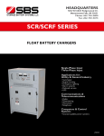
SCR/SCRF SERIES
FLOAT BATTERY CHARGERS
4
Forced Load Sharing
• Chargers operating in parallel share load
to within 2% of output current of each
charger.
Single-Phase Input
STYLE 1B CABINET CONSTRUCTION
5
6
12
16
20
25
30
35
40
50
60
75
100
14
18
12
6
13
15
16
11
4
1
2
11
3
19
High DC Voltage Charger Shutdown
• A contact closure from a high
DC voltage alarm activates the shutdown
circuit and charger output current goes
to zero.
21
22
23
24
7
8
10
9
5
6
1.
2.
3.
4.
5.
6.
Input Lightning Arrestors
• Provides additional input protection
against lightning-induced transients,
ANSI 37.90A
7.
8.
9.
10.
11.
Surge Withstand Capability
• Additional surge protection to meet
performance requirements of IEEE-472
SWC specification
12.
13.
14.
15.
16.
17.
18.
19.
20.
21.
22.
23.
24.
25.
Additional Optional Accessories
• Special input voltages and frequencies
• Device nameplates
• Special paint
• Special high-interrupting capacity
• Fungus proofing (tropicalization)
• NEMA-4 or NEMA-12 cabinets
• (AIC) circuit breakers
• Drip-proof cabinet shields
• Special hypalon internal wiring,
switchboard type
• 1% accuracy panel or switchboard
meters
Alarm
buzzer
•
• Cabinet heater strips
• Export packing
DC AMMETER
DC VOLTMETER
AC POWER “ON” LIGHT
EQUALIZE ADJUST LIGHT
FLOAT ADJUST POT
EQUALIZE TIMER (optional)
FLOAT EQUALIZE SWITCH (standard)
DC CIRCUIT BREAKER (optional)
DC FUSE(S)
AC CIRCUIT BREAKER
DC SURGE SUPPRESSOR
STATUS INDICATING LIGHTS
& SWITCHES (optional)
POWER ISOLATION TRANSFORMER
w/AC RECONNECTION T.B.
AC SURGE SUPPRESSORS
SCR RECTIFIER/HEAT SINK ASSEMBLY
POLARITY & BLOCKING
DIODE ASSEMBLIES
FILTER CHOKE(S)
BLEEDER RESISTOR
FILTER CAPACITORS
ALARM RELAY(S) (optional)
ALARM CONTROL MODULES (optional)
CONTROL MODULE
CURRENT LIMIT ADJUST POT
INPUT LINE & GROUND TERMINALS (TB1)
OUTPUT TERMINALS (TB2)
REMOTE ALARM TERMINALS (TB3)
18
7
17
8
19
9
20
10
22
25
24
STYLE 2 CABINET CONSTRUCTION
3
11
2
6
1
4
80 (36)
90 (41)
98 (44)
105 (48)
120 (54)
130 (59)
135 (61)
145 (66)
160 (73)
185 (84)
205 (93)
280 (127)
90
105
115
125
135
150
160
180
190
210
245
320
(41)
(48)
(52)
(57)
(61)
(68)
(73)
(82)
(86)
(95)
(111)
(145)
105
120
135
160
170
190
210
220
245
–
330
440
(48)
(54)
(61)
(73)
(77)
(86)
(95)
(100)
(111)
125
160
210
220
230
250
340
–
440
(57)
(73)
(95)
(100)
(104)
(113)
(154)
17
7
8
600
750
990
2
2
3
215 (98)
240 (109)
315 (143)
–
–
740
880
1100
1470
1840
2200
2570
2940
3670
4400
5870
7340
8800
–
–
2
2
2
3
3
3
3
3
3
4
4
4
4
–
–
210
240
275
360
425
480
510
550
600
710
780
850
925
(95)
(109)
(125)
(163)
(193)
(218)
(231)
(249)
(272)
(322)
(354)
(386)
(420)
Ordering Information
9
Specify:
• Charger model number:
21
X SCR X XXX—XXX—X
“1” or “3” phase input
Omit for unfiltered, or add “F” for filtered
“012”, “024”, “048”, “130” or
“260” nominal Vdc output
“006” to “600” rated Adc output
Omit if not required, or add “–E” for filtered
battery eliminator (SCRF units only)
22
10
19
20
18
• Nominal input (Vac) and frequency (Hz)
• Number and type of battery cells
• All optional accessories required on charger
Consult factory for higher dc voltage output and dc current outputs.
Specifications and performance data subject to change without notice.
14
15
Single-Phase Input
Three-Phase Input
(150)
(200)
–
–
1230
1480
1850
2460
3080
3690
4300
4920
6150
7380
9830
12300
14800
–
–
2
2
2
3
3
3
3
3
4
4
4
5
5
–
–
255
320
350
460
500
540
600
650
750
860
950
1350
1500
(116)
(145)
(159)
(209)
(227)
(245)
(272)
(295)
(340)
(390)
(431)
(612)
(680)
–
1260
1510
1760
2010
2510
3010
3760
5010
6260
7510
8760
10100
12600
15100
20100
25100
30100
–
2
2
2
2
3
3
3
3
3
4
4
4
5
5
5
5
5
–
300
330
355
380
500
520
550
680
750
915
1010
1100
1400
1500
1650
1820
1950
1260
–
1960
–
2750
–
3920
–
5880
7840
–
11800
–
15700
–
23600
(136)
(150)
(161)
(172)
(227)
(236)
(249)
(308)
(340)
(415)
(458)
(499)
(635)
(680)
(748)
(826)
( 885)
2
–
3
–
3
–
3
–
4
4
–
5
–
5
–
5
Fold B
350 (159)
–
510 (231)
–
560 (254)
–
590 (268)
–
890 (404)
1000 (454)
–
1480 (671)
1610 (730)
–
1950 (885)
Cabinet Dimensions
1A
CABINET STYLE
TYPE MOUNTING
DIMENSIONS
(inches)
1B
2
Wall*** Wall*** Floor***
3
4
5
Floor
Floor
Floor
38
H
15
26 ⁄
37 ⁄
49
62
80
W
181⁄4
19
203⁄8
32
42
58
D
121⁄8
151⁄2
143⁄4
24
24
30
14
***Rack-mounting cabinet is optional for these styles.
HOPPECKE Batteries Inc.
1960 Old Cuthbert Road, Suite 130, Cherry Hill, NJ 08034, U.S.A.
12
Industry’s First Choice for
Time-Tested Proven Reliability
(200)
*Heat loss in BTU/hr. is stated for nominal number of cells at float voltage and 100% dc load current. **Consult factory for ampere and voltage ratings
up to 1000A and 600V.
11
16
5
1A
1A
1A
1A
1B
1B
1B
1B
1B
2
2
3
Three-Phase Input
16
20
25
30
35
40
50
60
75
100
125
150
175
200
250
300
400
500
600
21
23
70
135
180
230
290
340
400
460
570
680
850
1130
Phone: 856-616-0032
Fax:
856-616-0132
Further information: www.hoppecke-us.com
13
Fold C
JF5010-00 Rev. 01
Applications for:
Utility & General Industry
• Switchgear
• Engine starting
• Emergency lighting
• Alarm systems
• Railroad service
• UPS
Communications &
Telecommunications
• Radio
• Telemetering
• Microwave
• Telephone
Computers & Control
Systems
• Uninterruptible power systems
Motive Power Systems
Reserve Power Systems
Special Power Systems
Motive Power Systems
Service
Reserve Power Systems
Special Power Systems
Service
Motive Power Systems
Reserve Power Systems
Special Power Systems
Service
Motive Power Systems
TYPICAL SCR/SCRF BATTERY CHARGER
INTERNAL CONSTRUCTION DETAIL
CASM, Combined
Alarm - Status Monitor*
The following alarm relays are available
combined together on a single board. Each
relay has one (1) set of isolated, dry form
“C” contacts (SPDT) wired to a terminal
strip for customer connection.Two (2)
sets of form “C” contacts (DPDT) are
available at additional cost, as are one (1)
set of latching relays.
• High-Low AC Voltage
Alarm Relay
With high and low indicating lights, 15second time delay on alarm, auto reset
1A
1A
1A
1A
1B
1B
1B
1B
1B
2
2
3
170
330
440
540
680
810
950
1080
1350
–
2020
2700
1A
1A
1B
1B
1B
1B
1B
1B
2
–
2
3
370
740
990
1230
1540
1850
2150
–
3080
1B
1B
1B
1B
1B
1B
2
–
2
Shipping
Weight (approx.)
lbs. (kg)
95
200
260
320
400
480
560
640
800
960
1200
1600
Cabinet Style
11
12
Heat Loss
BTU/hr.*
3
260Vdc
Shipping
Weight (approx.)
lbs. (kg)
2
Cabinet Style
1
Heat Loss
BTU/hr.*
11
**
130Vdc
Shipping
Weight (approx.)
lbs. (kg)
16
Cabinet Style
15
48Vdc
Heat Loss
BTU/hr.*
AC Input Voltmeter
and/or Ammeter
• Front-panel, 2% accuracy, 3.5-inch case,
1% 3.5-inch case, 1% 4.5-inch case,
switchboard or digital
*Alarm contacts are rated for 0.5A @ 120V AC or DC.
Indicating lights are red LED’s front panel mounted. A
“lamp test” switch is provided for verifying operation of
indicating lights. Customer terminal strip is rated 15A @
120V AC or DC to accommodate #14AWG maximum
wire. This option may be ordered without ground detection for DC systems that are referenced to ground.
14
Cabinet Style
Equalize Timers
• 0-72hr. Manual Equalize Timer
w/ or w/o Float Equalize Indicating
Lights
Replaces float/equalize switch. Charger
automatically switches from “equalize” to
“float” at end of set time interval.
• 0-72hr. Line Failure Auto-Equalize
Timer w/Float Equalize Indicating
Lights
Charger is switched to equalize for a set
time interval after power is interrupted
for 10 seconds or more. Equipped with
“float reset” and “equalize” override switches.
• 0-72hr. Current Limit Auto-Equalize
Timer w/Float Equalize Indicating
Lights
Charger is switched to equalize for a set
time interval after charger is in current
limit for 10 seconds or more. Equipped
with “float reset” and “equalize”
override switches.
•
13
Heat Loss
BTU/hr.*
*Alarm circuits provide one (1) set of dry form “C”
contacts (SPDT) wired to a terminal strip for customer
termination. Alarm circuits with two (2) sets of dry form
“C” contacts (DPDT) are available without indicating
lights at additional cost. Standard relay contacts are
rated for resistive loads of: 1A @ 120Vac, 2A @ 28Vdc,
1A @ 52Vdc, 0.1A @ 130Vdc. Auxiliary relays are
available for use with alarm circuits when alarm load
exceeds the standard contact rating. Auxiliary relay
contacts are rated for resistive loads of: 5A @ 120Vac,
5A @ 28Vdc, 2A @ 52Vdc, 0.5A @ 130Vdc.
•
STYLE 1A CABINET CONSTRUCTION
24Vdc
Shipping
Weight (approx.)
lbs. (kg)
Filtered Battery Eliminator
• Output ripple voltage is 30mVrms or
0.06% of nominal output voltage,
whichever is higher, without battery
connected.
•
12Vdc
DC Circuit Breaker
Two-pole DC breaker is installed with
one-pole standard fuse:
• 5000 AIC, UL Listed 100A-Frame
• 10000 AIC, UL Listed 250 & 400A-Frame
• 14000 AIC, UL Listed 600 & 800A-Frame
• Optional higher AIC circuit breakers are
available.
Special Power Systems
Service
SCR/SCRF Battery Charger Heat Loss, Size, & Weight Data Table
Cabinet Style
DC Ground Detection for Local
Indication
• Ground Detection Switch for
Front Panel DC Voltmeter
Indication
Measures voltage from + or – output
terminals to common ground
• Ground Detection Indicating Lights
with Ground Test & Lamp Test
Switch
Front panel lamps indicate + or – output
ground fault with switch in “ground test”
position. In “lamp test” position both
lights are verified as operational.
•
With indicating light,15-second time
delay on alarm, auto reset
Low DC Voltage Alarm Relay
With indicating light,15-second time
delay on alarm, auto reset
Ground Detection Alarm Relay
With (+) ground detection indicating
light and (–) ground detection indicating
light, 15-second time delay on alarm, auto
reset
Charger Failure Alarm Relay
With indicating light, 30-second time
delay on alarm, auto reset
Common Alarm Relay
Summary alarm relay for any one or all
alarms on this board.
AC Fuse
• Two-pole AC fuse for single-phase, 3-pole
AC fuse for 3-phase
Heat Loss
BTU/hr.*
• High DC Voltage Alarm Relay
Ampere
Rating*
Alarm Relays for
Remote Indication*
Available with or without front panel alarm
indicating lights
• AC Power Failure Alarm
Provides alarm state when AC power
fails or AC breaker is open
• DC Ground Detection Alarms
Provides alarm state when a ground fault
has occurred at either the + or – output
terminal
• High-Low DC Voltage Alarms
Provides high alarm state when battery is
being overcharged and low alarm state
when battery is near end of discharge
• Charger Failure Alarm
(No DC Current)
Provides alarm state when charger
output current is less than 2% of rated
output for 30 seconds or more.Will also
activate with AC power failure and/or DC
breaker or fuse open.
• Battery Discharging Alarm
Provides alarm state when battery
discharge current exceeds the
charger recharge current
• End of Discharge Alarm
Provides alarm state when battery has
discharged to lowest system voltage limit
• DC Current Limit Alarm
Provides alarm state when charger
output current reaches the current limit
setting
• Common (Summary) Alarm
Provides a single alarm state when any one
or all monitored alarm conditions exist on
charger
Shipping
Weight (approx.)
lbs. (kg)
SCR/SCRF BATTERY CHARGER OPTIONAL ACCESSORIES
Reserve Power Systems
670
–
1790
–
2790
–
2
–
2
–
3
–
230 (104)
–
320 (145)
–
490 (222)
–
SCR/SCRF SERIES
FLOAT BATTERY CHARGERS
4
Forced Load Sharing
• Chargers operating in parallel share load
to within 2% of output current of each
charger.
Single-Phase Input
STYLE 1B CABINET CONSTRUCTION
5
6
12
16
20
25
30
35
40
50
60
75
100
14
18
12
6
13
15
16
11
4
1
2
11
3
19
High DC Voltage Charger Shutdown
• A contact closure from a high
DC voltage alarm activates the shutdown
circuit and charger output current goes
to zero.
21
22
23
24
7
8
10
9
5
6
1.
2.
3.
4.
5.
6.
Input Lightning Arrestors
• Provides additional input protection
against lightning-induced transients,
ANSI 37.90A
7.
8.
9.
10.
11.
Surge Withstand Capability
• Additional surge protection to meet
performance requirements of IEEE-472
SWC specification
12.
13.
14.
15.
16.
17.
18.
19.
20.
21.
22.
23.
24.
25.
Additional Optional Accessories
• Special input voltages and frequencies
• Device nameplates
• Special paint
• Special high-interrupting capacity
• Fungus proofing (tropicalization)
• NEMA-4 or NEMA-12 cabinets
• (AIC) circuit breakers
• Drip-proof cabinet shields
• Special hypalon internal wiring,
switchboard type
• 1% accuracy panel or switchboard
meters
Alarm
buzzer
•
• Cabinet heater strips
• Export packing
DC AMMETER
DC VOLTMETER
AC POWER “ON” LIGHT
EQUALIZE ADJUST LIGHT
FLOAT ADJUST POT
EQUALIZE TIMER (optional)
FLOAT EQUALIZE SWITCH (standard)
DC CIRCUIT BREAKER (optional)
DC FUSE(S)
AC CIRCUIT BREAKER
DC SURGE SUPPRESSOR
STATUS INDICATING LIGHTS
& SWITCHES (optional)
POWER ISOLATION TRANSFORMER
w/AC RECONNECTION T.B.
AC SURGE SUPPRESSORS
SCR RECTIFIER/HEAT SINK ASSEMBLY
POLARITY & BLOCKING
DIODE ASSEMBLIES
FILTER CHOKE(S)
BLEEDER RESISTOR
FILTER CAPACITORS
ALARM RELAY(S) (optional)
ALARM CONTROL MODULES (optional)
CONTROL MODULE
CURRENT LIMIT ADJUST POT
INPUT LINE & GROUND TERMINALS (TB1)
OUTPUT TERMINALS (TB2)
REMOTE ALARM TERMINALS (TB3)
18
7
17
8
19
9
20
10
22
25
24
STYLE 2 CABINET CONSTRUCTION
3
11
2
6
1
4
80 (36)
90 (41)
98 (44)
105 (48)
120 (54)
130 (59)
135 (61)
145 (66)
160 (73)
185 (84)
205 (93)
280 (127)
90
105
115
125
135
150
160
180
190
210
245
320
(41)
(48)
(52)
(57)
(61)
(68)
(73)
(82)
(86)
(95)
(111)
(145)
105
120
135
160
170
190
210
220
245
–
330
440
(48)
(54)
(61)
(73)
(77)
(86)
(95)
(100)
(111)
125
160
210
220
230
250
340
–
440
(57)
(73)
(95)
(100)
(104)
(113)
(154)
17
7
8
600
750
990
2
2
3
215 (98)
240 (109)
315 (143)
–
–
740
880
1100
1470
1840
2200
2570
2940
3670
4400
5870
7340
8800
–
–
2
2
2
3
3
3
3
3
3
4
4
4
4
–
–
210
240
275
360
425
480
510
550
600
710
780
850
925
(95)
(109)
(125)
(163)
(193)
(218)
(231)
(249)
(272)
(322)
(354)
(386)
(420)
Ordering Information
9
Specify:
• Charger model number:
21
X SCR X XXX—XXX—X
“1” or “3” phase input
Omit for unfiltered, or add “F” for filtered
“012”, “024”, “048”, “130” or
“260” nominal Vdc output
“006” to “600” rated Adc output
Omit if not required, or add “–E” for filtered
battery eliminator (SCRF units only)
22
10
19
20
18
• Nominal input (Vac) and frequency (Hz)
• Number and type of battery cells
• All optional accessories required on charger
Consult factory for higher dc voltage output and dc current outputs.
Specifications and performance data subject to change without notice.
14
15
Single-Phase Input
Three-Phase Input
(150)
(200)
–
–
1230
1480
1850
2460
3080
3690
4300
4920
6150
7380
9830
12300
14800
–
–
2
2
2
3
3
3
3
3
4
4
4
5
5
–
–
255
320
350
460
500
540
600
650
750
860
950
1350
1500
(116)
(145)
(159)
(209)
(227)
(245)
(272)
(295)
(340)
(390)
(431)
(612)
(680)
–
1260
1510
1760
2010
2510
3010
3760
5010
6260
7510
8760
10100
12600
15100
20100
25100
30100
–
2
2
2
2
3
3
3
3
3
4
4
4
5
5
5
5
5
–
300
330
355
380
500
520
550
680
750
915
1010
1100
1400
1500
1650
1820
1950
1260
–
1960
–
2750
–
3920
–
5880
7840
–
11800
–
15700
–
23600
(136)
(150)
(161)
(172)
(227)
(236)
(249)
(308)
(340)
(415)
(458)
(499)
(635)
(680)
(748)
(826)
( 885)
2
–
3
–
3
–
3
–
4
4
–
5
–
5
–
5
Fold B
350 (159)
–
510 (231)
–
560 (254)
–
590 (268)
–
890 (404)
1000 (454)
–
1480 (671)
1610 (730)
–
1950 (885)
Cabinet Dimensions
1A
CABINET STYLE
TYPE MOUNTING
DIMENSIONS
(inches)
1B
2
Wall*** Wall*** Floor***
3
4
5
Floor
Floor
Floor
38
H
15
26 ⁄
37 ⁄
49
62
80
W
181⁄4
19
203⁄8
32
42
58
D
121⁄8
151⁄2
143⁄4
24
24
30
14
***Rack-mounting cabinet is optional for these styles.
HOPPECKE Batteries Inc.
1960 Old Cuthbert Road, Suite 130, Cherry Hill, NJ 08034, U.S.A.
12
Industry’s First Choice for
Time-Tested Proven Reliability
(200)
*Heat loss in BTU/hr. is stated for nominal number of cells at float voltage and 100% dc load current. **Consult factory for ampere and voltage ratings
up to 1000A and 600V.
11
16
5
1A
1A
1A
1A
1B
1B
1B
1B
1B
2
2
3
Three-Phase Input
16
20
25
30
35
40
50
60
75
100
125
150
175
200
250
300
400
500
600
21
23
70
135
180
230
290
340
400
460
570
680
850
1130
Phone: 856-616-0032
Fax:
856-616-0132
Further information: www.hoppecke-us.com
13
Fold C
JF5010-00 Rev. 01
Applications for:
Utility & General Industry
• Switchgear
• Engine starting
• Emergency lighting
• Alarm systems
• Railroad service
• UPS
Communications &
Telecommunications
• Radio
• Telemetering
• Microwave
• Telephone
Computers & Control
Systems
• Uninterruptible power systems
Motive Power Systems
Reserve Power Systems
Special Power Systems
Motive Power Systems
Service
Reserve Power Systems
Special Power Systems
Service
Motive Power Systems
Reserve Power Systems
Special Power Systems
Service
Motive Power Systems
TYPICAL SCR/SCRF BATTERY CHARGER
INTERNAL CONSTRUCTION DETAIL
CASM, Combined
Alarm - Status Monitor*
The following alarm relays are available
combined together on a single board. Each
relay has one (1) set of isolated, dry form
“C” contacts (SPDT) wired to a terminal
strip for customer connection.Two (2)
sets of form “C” contacts (DPDT) are
available at additional cost, as are one (1)
set of latching relays.
• High-Low AC Voltage
Alarm Relay
With high and low indicating lights, 15second time delay on alarm, auto reset
1A
1A
1A
1A
1B
1B
1B
1B
1B
2
2
3
170
330
440
540
680
810
950
1080
1350
–
2020
2700
1A
1A
1B
1B
1B
1B
1B
1B
2
–
2
3
370
740
990
1230
1540
1850
2150
–
3080
1B
1B
1B
1B
1B
1B
2
–
2
Shipping
Weight (approx.)
lbs. (kg)
95
200
260
320
400
480
560
640
800
960
1200
1600
Cabinet Style
11
12
Heat Loss
BTU/hr.*
3
260Vdc
Shipping
Weight (approx.)
lbs. (kg)
2
Cabinet Style
1
Heat Loss
BTU/hr.*
11
**
130Vdc
Shipping
Weight (approx.)
lbs. (kg)
16
Cabinet Style
15
48Vdc
Heat Loss
BTU/hr.*
AC Input Voltmeter
and/or Ammeter
• Front-panel, 2% accuracy, 3.5-inch case,
1% 3.5-inch case, 1% 4.5-inch case,
switchboard or digital
*Alarm contacts are rated for 0.5A @ 120V AC or DC.
Indicating lights are red LED’s front panel mounted. A
“lamp test” switch is provided for verifying operation of
indicating lights. Customer terminal strip is rated 15A @
120V AC or DC to accommodate #14AWG maximum
wire. This option may be ordered without ground detection for DC systems that are referenced to ground.
14
Cabinet Style
Equalize Timers
• 0-72hr. Manual Equalize Timer
w/ or w/o Float Equalize Indicating
Lights
Replaces float/equalize switch. Charger
automatically switches from “equalize” to
“float” at end of set time interval.
• 0-72hr. Line Failure Auto-Equalize
Timer w/Float Equalize Indicating
Lights
Charger is switched to equalize for a set
time interval after power is interrupted
for 10 seconds or more. Equipped with
“float reset” and “equalize” override switches.
• 0-72hr. Current Limit Auto-Equalize
Timer w/Float Equalize Indicating
Lights
Charger is switched to equalize for a set
time interval after charger is in current
limit for 10 seconds or more. Equipped
with “float reset” and “equalize”
override switches.
•
13
Heat Loss
BTU/hr.*
*Alarm circuits provide one (1) set of dry form “C”
contacts (SPDT) wired to a terminal strip for customer
termination. Alarm circuits with two (2) sets of dry form
“C” contacts (DPDT) are available without indicating
lights at additional cost. Standard relay contacts are
rated for resistive loads of: 1A @ 120Vac, 2A @ 28Vdc,
1A @ 52Vdc, 0.1A @ 130Vdc. Auxiliary relays are
available for use with alarm circuits when alarm load
exceeds the standard contact rating. Auxiliary relay
contacts are rated for resistive loads of: 5A @ 120Vac,
5A @ 28Vdc, 2A @ 52Vdc, 0.5A @ 130Vdc.
•
STYLE 1A CABINET CONSTRUCTION
24Vdc
Shipping
Weight (approx.)
lbs. (kg)
Filtered Battery Eliminator
• Output ripple voltage is 30mVrms or
0.06% of nominal output voltage,
whichever is higher, without battery
connected.
•
12Vdc
DC Circuit Breaker
Two-pole DC breaker is installed with
one-pole standard fuse:
• 5000 AIC, UL Listed 100A-Frame
• 10000 AIC, UL Listed 250 & 400A-Frame
• 14000 AIC, UL Listed 600 & 800A-Frame
• Optional higher AIC circuit breakers are
available.
Special Power Systems
Service
SCR/SCRF Battery Charger Heat Loss, Size, & Weight Data Table
Cabinet Style
DC Ground Detection for Local
Indication
• Ground Detection Switch for
Front Panel DC Voltmeter
Indication
Measures voltage from + or – output
terminals to common ground
• Ground Detection Indicating Lights
with Ground Test & Lamp Test
Switch
Front panel lamps indicate + or – output
ground fault with switch in “ground test”
position. In “lamp test” position both
lights are verified as operational.
•
With indicating light,15-second time
delay on alarm, auto reset
Low DC Voltage Alarm Relay
With indicating light,15-second time
delay on alarm, auto reset
Ground Detection Alarm Relay
With (+) ground detection indicating
light and (–) ground detection indicating
light, 15-second time delay on alarm, auto
reset
Charger Failure Alarm Relay
With indicating light, 30-second time
delay on alarm, auto reset
Common Alarm Relay
Summary alarm relay for any one or all
alarms on this board.
AC Fuse
• Two-pole AC fuse for single-phase, 3-pole
AC fuse for 3-phase
Heat Loss
BTU/hr.*
• High DC Voltage Alarm Relay
Ampere
Rating*
Alarm Relays for
Remote Indication*
Available with or without front panel alarm
indicating lights
• AC Power Failure Alarm
Provides alarm state when AC power
fails or AC breaker is open
• DC Ground Detection Alarms
Provides alarm state when a ground fault
has occurred at either the + or – output
terminal
• High-Low DC Voltage Alarms
Provides high alarm state when battery is
being overcharged and low alarm state
when battery is near end of discharge
• Charger Failure Alarm
(No DC Current)
Provides alarm state when charger
output current is less than 2% of rated
output for 30 seconds or more.Will also
activate with AC power failure and/or DC
breaker or fuse open.
• Battery Discharging Alarm
Provides alarm state when battery
discharge current exceeds the
charger recharge current
• End of Discharge Alarm
Provides alarm state when battery has
discharged to lowest system voltage limit
• DC Current Limit Alarm
Provides alarm state when charger
output current reaches the current limit
setting
• Common (Summary) Alarm
Provides a single alarm state when any one
or all monitored alarm conditions exist on
charger
Shipping
Weight (approx.)
lbs. (kg)
SCR/SCRF BATTERY CHARGER OPTIONAL ACCESSORIES
Reserve Power Systems
670
–
1790
–
2790
–
2
–
2
–
3
–
230 (104)
–
320 (145)
–
490 (222)
–
SCR/SCRF SERIES
FLOAT BATTERY CHARGERS
4
Forced Load Sharing
• Chargers operating in parallel share load
to within 2% of output current of each
charger.
Single-Phase Input
STYLE 1B CABINET CONSTRUCTION
5
6
12
16
20
25
30
35
40
50
60
75
100
14
18
12
6
13
15
16
11
4
1
2
11
3
19
High DC Voltage Charger Shutdown
• A contact closure from a high
DC voltage alarm activates the shutdown
circuit and charger output current goes
to zero.
21
22
23
24
7
8
10
9
5
6
1.
2.
3.
4.
5.
6.
Input Lightning Arrestors
• Provides additional input protection
against lightning-induced transients,
ANSI 37.90A
7.
8.
9.
10.
11.
Surge Withstand Capability
• Additional surge protection to meet
performance requirements of IEEE-472
SWC specification
12.
13.
14.
15.
16.
17.
18.
19.
20.
21.
22.
23.
24.
25.
Additional Optional Accessories
• Special input voltages and frequencies
• Device nameplates
• Special paint
• Special high-interrupting capacity
• Fungus proofing (tropicalization)
• NEMA-4 or NEMA-12 cabinets
• (AIC) circuit breakers
• Drip-proof cabinet shields
• Special hypalon internal wiring,
switchboard type
• 1% accuracy panel or switchboard
meters
Alarm
buzzer
•
• Cabinet heater strips
• Export packing
DC AMMETER
DC VOLTMETER
AC POWER “ON” LIGHT
EQUALIZE ADJUST LIGHT
FLOAT ADJUST POT
EQUALIZE TIMER (optional)
FLOAT EQUALIZE SWITCH (standard)
DC CIRCUIT BREAKER (optional)
DC FUSE(S)
AC CIRCUIT BREAKER
DC SURGE SUPPRESSOR
STATUS INDICATING LIGHTS
& SWITCHES (optional)
POWER ISOLATION TRANSFORMER
w/AC RECONNECTION T.B.
AC SURGE SUPPRESSORS
SCR RECTIFIER/HEAT SINK ASSEMBLY
POLARITY & BLOCKING
DIODE ASSEMBLIES
FILTER CHOKE(S)
BLEEDER RESISTOR
FILTER CAPACITORS
ALARM RELAY(S) (optional)
ALARM CONTROL MODULES (optional)
CONTROL MODULE
CURRENT LIMIT ADJUST POT
INPUT LINE & GROUND TERMINALS (TB1)
OUTPUT TERMINALS (TB2)
REMOTE ALARM TERMINALS (TB3)
18
7
17
8
19
9
20
10
22
25
24
STYLE 2 CABINET CONSTRUCTION
3
11
2
6
1
4
80 (36)
90 (41)
98 (44)
105 (48)
120 (54)
130 (59)
135 (61)
145 (66)
160 (73)
185 (84)
205 (93)
280 (127)
90
105
115
125
135
150
160
180
190
210
245
320
(41)
(48)
(52)
(57)
(61)
(68)
(73)
(82)
(86)
(95)
(111)
(145)
105
120
135
160
170
190
210
220
245
–
330
440
(48)
(54)
(61)
(73)
(77)
(86)
(95)
(100)
(111)
125
160
210
220
230
250
340
–
440
(57)
(73)
(95)
(100)
(104)
(113)
(154)
17
7
8
600
750
990
2
2
3
215 (98)
240 (109)
315 (143)
–
–
740
880
1100
1470
1840
2200
2570
2940
3670
4400
5870
7340
8800
–
–
2
2
2
3
3
3
3
3
3
4
4
4
4
–
–
210
240
275
360
425
480
510
550
600
710
780
850
925
(95)
(109)
(125)
(163)
(193)
(218)
(231)
(249)
(272)
(322)
(354)
(386)
(420)
Ordering Information
9
Specify:
• Charger model number:
21
X SCR X XXX—XXX—X
“1” or “3” phase input
Omit for unfiltered, or add “F” for filtered
“012”, “024”, “048”, “130” or
“260” nominal Vdc output
“006” to “600” rated Adc output
Omit if not required, or add “–E” for filtered
battery eliminator (SCRF units only)
22
10
19
20
18
• Nominal input (Vac) and frequency (Hz)
• Number and type of battery cells
• All optional accessories required on charger
Consult factory for higher dc voltage output and dc current outputs.
Specifications and performance data subject to change without notice.
14
15
Single-Phase Input
Three-Phase Input
(150)
(200)
–
–
1230
1480
1850
2460
3080
3690
4300
4920
6150
7380
9830
12300
14800
–
–
2
2
2
3
3
3
3
3
4
4
4
5
5
–
–
255
320
350
460
500
540
600
650
750
860
950
1350
1500
(116)
(145)
(159)
(209)
(227)
(245)
(272)
(295)
(340)
(390)
(431)
(612)
(680)
–
1260
1510
1760
2010
2510
3010
3760
5010
6260
7510
8760
10100
12600
15100
20100
25100
30100
–
2
2
2
2
3
3
3
3
3
4
4
4
5
5
5
5
5
–
300
330
355
380
500
520
550
680
750
915
1010
1100
1400
1500
1650
1820
1950
1260
–
1960
–
2750
–
3920
–
5880
7840
–
11800
–
15700
–
23600
(136)
(150)
(161)
(172)
(227)
(236)
(249)
(308)
(340)
(415)
(458)
(499)
(635)
(680)
(748)
(826)
( 885)
2
–
3
–
3
–
3
–
4
4
–
5
–
5
–
5
Fold B
350 (159)
–
510 (231)
–
560 (254)
–
590 (268)
–
890 (404)
1000 (454)
–
1480 (671)
1610 (730)
–
1950 (885)
Cabinet Dimensions
1A
CABINET STYLE
TYPE MOUNTING
DIMENSIONS
(inches)
1B
2
Wall*** Wall*** Floor***
3
4
5
Floor
Floor
Floor
38
H
15
26 ⁄
37 ⁄
49
62
80
W
181⁄4
19
203⁄8
32
42
58
D
121⁄8
151⁄2
143⁄4
24
24
30
14
***Rack-mounting cabinet is optional for these styles.
HOPPECKE Batteries Inc.
1960 Old Cuthbert Road, Suite 130, Cherry Hill, NJ 08034, U.S.A.
12
Industry’s First Choice for
Time-Tested Proven Reliability
(200)
*Heat loss in BTU/hr. is stated for nominal number of cells at float voltage and 100% dc load current. **Consult factory for ampere and voltage ratings
up to 1000A and 600V.
11
16
5
1A
1A
1A
1A
1B
1B
1B
1B
1B
2
2
3
Three-Phase Input
16
20
25
30
35
40
50
60
75
100
125
150
175
200
250
300
400
500
600
21
23
70
135
180
230
290
340
400
460
570
680
850
1130
Phone: 856-616-0032
Fax:
856-616-0132
Further information: www.hoppecke-us.com
13
Fold C
JF5010-00 Rev. 01
Applications for:
Utility & General Industry
• Switchgear
• Engine starting
• Emergency lighting
• Alarm systems
• Railroad service
• UPS
Communications &
Telecommunications
• Radio
• Telemetering
• Microwave
• Telephone
Computers & Control
Systems
• Uninterruptible power systems
Component Selection
• Electronic and electrical components
are substantially derated to assure
long life and reliability.Typical MTBF
is100,000 hours minimum.
Components are selected or
designed to provide a system life
expectancy in excess of 30 years.
Modular Construction
• Control circuits, alarm circuits and
electrical sub-assemblies are printed
circuit board wired or modularized
with plug and socket connections for
easy serviceability.
Standard Sub-assemblies
• Control modules and many electrical
sub-assemblies are standardized
across the entire range of charger
sizes.This minimizes spare parts
inventory and simplifies maintenance.
Durable
• Front panels are recessed to prevent
accidental damage to meters and
controls. Standard cabinets are
NEMA-1 enclosures of heavy-gauge
phosphatized steel with an attractive,
long-lasting acrylic enamel finish.
Fold C
Easy Troubleshooting
• A complete service manual,
color-coded wiring, test-point
identification and circuit-symbol
labeling of internal components
make troubleshooting easy.
Ease of Adjustment
• Tap adjustments are not required.
Output float voltage, equalize voltage,
current limit and alarm levels are
potentiometer adjustable.
Ease of Access
• Internal components and connections
are easily accessible and/or removable
through a hinged front door that
opens approximately 180 degrees
for easy serviceability.
Ease of Installation
• Cabinets are floor, wall or rack
mountable and equipped with
knockouts for cable or conduit
entrance. Input, output and remote
alarm connections are wired to easily
accessible, internal terminal blocks.
Motive Power Systems
ELECTRICAL
SPECIFICATIONS
AC Input
• Standard transformers are
available with taps for nominal
voltages as listed below.
Single-Phase Voltages:
• 120/220 – 240V 47 – 63Hz
• 480V
57 – 63Hz
• 120/208 – 240V 47 – 63Hz(optional)
Three-Phase Voltages:
• 208 – 240V
57 – 63Hz
• 380 – 416V
47 – 63Hz
• 480V
57 – 63Hz
Chargers are wired and circuit
protected for one nominal input
voltage and frequency to be
specified at time of order.
Output Regulation
• ±0.5% of DC voltage setting maintained with input line variations of
-12%, +10% voltage and/or ±5%
frequency
• ±0.5% of DC voltage setting
maintained with load variations from
no load to full load
• ±1.0% of DC voltage setting maintained against the combined variations of line, load and temperature
ENVIRONMENTAL
SPECIFICATIONS
Operating Ambient Temperature
• 32°F to 122°F (0°C to 50°C)
without derating
Output Transient Response
& Recovery
• ±5.0% max. of DC voltage setting
maintained with step load changes
from 20% to 100% load
Storage Temperature
• -40°F to 185°F (-40°C to 85°C)
Operating Altitude
• 3300 feet (1000 meters) above sea
level without derating
Random Parallel Operation
• SCR/SCRF Series Chargers may be
random parallel operated with other
chargers of similar regulation and
current limit characteristics. Equal
load sharing by two SCR-SCRF
chargers requires the addition of the
forced load sharing option.
AC Input Circuit Breaker
Single-Phase Input:
• Two-pole, 7500 AIC, UL Listed
100A-Frame
Three-Phase Input:
• Three-pole, 7500 AIC, UL
Recognized 100A-Frame
• Three-pole, 25000 AIC, UL
Listed 225A-Frame
• Three-pole, 30000 AIC, UL Listed
400A and 600A-Frame
DC Output Fuses
• Two-pole, fast-acting, currentlimiting rectifier type
AC and DC Surge Suppressors
MOV Type
AC Withstand:
• 240Vac or less:
1500Vpk - 1.2x20 µsec pulse
• Over 240Vac:
3000Vpk - 1.2x20 µsec pulse
DC Withstand:
• All DC outputs: 4000Vpk 2x10 µsec pulse
Battery Eliminator Operation
• SCR/SCRF Series Chargers will
operate as DC power supplies
without batteries. Addition of the
Filtered Battery Eliminator option
will reduce ripple, when used as a
battery eliminator, to the greater of
0.06% or 30mV.
Motive Power Systems
Reserve Power Systems
Special Power Systems
Service
Typical SCR/SCRF Performance Curves
Output
Regulation – Lead-Acid Batteries
Output Regulation – Lead-Acid
Batteries
2.5
100
100
2.5
2.4
2.4
2.5
100
90
90
100
90
80
80
90
80
70
70
80
Output Regulation – Lead-Acid
Batteries
Output
Regulation – Lead-Acid Batteries
2.3
2.4
Equalize
Calcium–Float
2.2
2.1
Calcium–Float
Antimony–Float
2.1
2.2
Calcium–Float
Antimony–Float
70
60
60
70
2.1
2.0
Antimony–Float
2.0
2.1
Antimony–Float
60
50
50
60
2.0
1.9
1.9
2.0
50
40
40
50
1.9
1.8
1.8
1.9
40
30
30
40
1.8
1.7
1.7
1.8
2.2
2.3
1.7
1.6
1.60
Manual Float/Equalize Switch
• Front panel toggle switch
DC Output Blocking Diode
• Standard SCR/SCRF Series feature
prevents battery from discharging
back through the filter and rectifier
when charger is “off” due to AC
power failure or charger malfunction.
Float and Equalize Adjustment
Potentiometers
• Two front panel mounted, lockable
adjustment potentiometers
DC Output Protection Diode
• Prevents damage to charger and
battery due to reversed polarity
connections
Current Limit Adjustment
Potentiometer
• Internally mounted, with easily
accessible adjustment
Color-Coded Internal Wiring
• 600 Volt, color-coded, polyvinylchloride (PVC) wiring is standard.
Conversion Efficiency – Single-Phase
Charger
Conversion
Efficiency – Single-Phase Charger
Equalize
Calcium–Float
2.3
2.2
DC Output Ammeter
and Voltmeter
• Front panel, 2% accuracy, 3.5-inch case
Equalize
Equalize
2.4
2.3
Typical internal construction detail showing combined alarm-status charger monitor option
ConversionCharger
Efficiency – Single-Phase Charger
Conversion Efficiency – Single-Phase
2.5
30
20
20
10
1.6
1.7
0
1.6
50 110
60 120
70
10 20 30 40 50 6010 7020 8030 9040 100
0 % Load
0 % Load
Current
limit
10 20 30 40 50 60 1070 2080 3090 40100
50110
6012070
adjustment
% Load
% Load
Current limit
1.7
Regulation – Ni-Cd Batteries
Output Regulation – Ni-CdOutput
Batteries
adjustment
1.6
1.5
1.5
1.4
1.4
1.3
100
90
100
90
80
80
90
80
70
70
80
70
60
60
70
Equalize
Equalize
Float
adjustment
100
90
1.5
1.6
Equalize
1.4
1.5
Float
1.3
1.4
Float
90 100 110 120
100
1.2
1.3
60
50
50
60
1.2
1.1
1.1
1.2
50
40
40
50
1.1
1.0
1.0
1.1
40
30
30
40
1.0
1.0
30
20
20
10
0
50 110
60 120
70
10 20 30 40 50 6010 7020 8030 9040 100
Load
0 % Load
0 % 60
Current
limit
10 20 30 40 50
70
80
90
100
110
120
10 20 30 40 50 60 70
adjustment
% Load
% Load
Current limit
90 100 110 120
80
Conversion Efficiency – Three-Phase
Charger
Conversion
Efficiency – Three-Phase Charger
1.3
1.2
0
80
Current limitEfficiency – Three-Phase
ConversionCharger
Efficiency – Three-Phase Charger
Conversion
1.7
Equalize
Float
10
20
100
0
10
80 90 100
50 110
60 120
70
10 110
20 120
30 40 50 6010 7020 8030 9040 100
Load
0 %Current
0 % Load
limit 30 40 50
10 110
20
60 1070 2080 3090 40100501106012070
80 90 100
adjustment 120
% Load
% Load
1.6
1.7
BatteriesRegulation – Ni-Cd Batteries
Output Regulation – Ni-Cd Output
1.7
1.6
20
30
20
30
10
20
100
0
10
80 90 100
50 110
60 120
70
10 110
20 120
30 40 50 6010 7020 8030 9040 100
Load
0 % Current
0 %60Load70 80 90 100 110 120
limit
10
20
30
40
50
80 90 100
110 120
10 20 30 40 50 60 70
adjustment
% Load
% Load
adjustment
80
90 100 110 120
80
90 100 110 120
Current limit
adjustment
Typical SCR/SCRF Series One-Line Circuit Diagram
UNREGULATED
AC INPUT, 1f OR 3f
Relative Humidity
• 5% to 95% (without condensation)
Service
AC On Indicating Light
• Green front panel indicator
Output Current Limit
• The electronic current limiting
circuitry is factory set at 110%
of rated output. It is continuously
adjustable from 90% to 120% of
rated load.
*Measured when connected to a battery with an 8-hr.,
Amp-Hour rating of 4 times the full load current rating
of the charger.
Special Power Systems
SCR/SCRF BATTERY
CHARGER STANDARD
ACCESSORIES
• Recovery to ±2.0% of DC voltage
setting typically 200msec
• Recovery to steady state DC voltage
setting typically 500msec
• Overshoot of DC voltage setting is
not present at turn-on due to “softstart” feature.
Output Ripple and
Electrical Noise*
• Unfiltered (SCR Series): Output ripple voltage is less than 10% RMS for
single-phase input SCR units. Output
ripple voltage is less than 3% RMS
for three-phase input SCR units.
• Filtered (SCRF Series): Output ripple
voltage is 30mVrms or less for all
SCRF units. Electrical voice band
noise is less than 32dBrnC using Cmessage weighting network.
Reserve Power Systems
% Efficiency
% Efficiency
Service
% Efficiency
% Efficiency
DESIGN FEATURES
Special Power Systems
% Efficiency
% Efficiency
HOPPECKE SCR/SCRF
Series of industrial float
chargers is designed to
automatically control
charging rates for a wide
variety of battery types
and to simultaneously
provide full-rated output
for both continuous and
intermittent dc loads.
The chargers are constant
voltage devices with automatic current
limiting. Voltage regulation and current limiting
are controlled by solid-state integrated circuitry to assure
maximum performance in minimum space.
The SCR/SCRF Series is ideally suited to utility, communications and
other stationary charger applications.
Reserve Power Systems
% Efficiency
% Efficiency
Motive Power Systems
Vdc/cell
Vdc/cell
Service
Vdc/cell
Vdc/cell
Special Power Systems
Vdc/cell
Vdc/cell
Reserve Power Systems
Vdc/cell
Vdc/cell
Motive Power Systems
AC INPUT
CIRCUIT BREAKER
INPUT SURGE
PROTECTION
POWER ISOLATION
TRANSFORMER
SCR/DIODE
RECTIFIER BRIDGE
REVERSE CURRENT
POLARITY
PROTECTION
FILTER SECTION
(SCRF only)
DC OUTPUT
CIRCUIT BREAKER
(optional)
OUTPUT FUSE
PROTECTION
OUTPUT SURGE
PROTECTION
REGULATED
DC OUTPUT
SCR/SCRF Battery Charger DC Output Table
Audible Noise
• Less than 65dBA at any point 5
feet from any vertical surface of
enclosure.Typical values measure
55 to 60dBA at 100% load.
VDC
Nominal
12
24
48
130
260
Ventilation
• Units rated 300Adc output or less
are convection cooled via NEMA-1
vent openings in cabinet. Units rated
400Adc output or greater have
fan-assisted convection cooling with
overheat-audible alarm and remotealarm contacts. (Automatic charger
shutdown due to overheat is optional.)
Float
Adjustment
Range (VDC)
Equalize
Adjustment
Range
(VDC)
10.5
23
46
115
230
11.3 - 16
24.5 - 32
48 - 64
124 - 150
245 - 300
-
14.5
30
60
140
280
Lead-Acid Cell
Capability (3)
(No. of Cells)
ADC Size Cell
Available (1)
1φInput
6 to 100
6 to 100
6 to 100
6 to 50
6 to 25
3φInput
60
50
50
25
16
to
to
to
to
to
100
600
600
600
300
Normal
5
11
22
55
110
-
6
13
26
62
124
AC “ON”
INDICATING LIGHT
Ni-Cd Cell
Capability (3)
(No. of Cells)
Reduced VPC
Normal
27
63
126
8 - 10
17 - 20
34 - 40
86 - 94
172 - 188
Reduced VPC
REMOTE ALARM SIGNAL
21
42
98
196
INTERNAL HVDC ALARM SIGNAL
(1) The discrete Adc sizes offered within the ranges listed above are: 6, 12, 16, 20, 25, 30, 35, 40, 50, 60, 75, 100, 125, 150, 175, 200, 250,
300, 400, 500, 600Adc. All sizes are rated at 100% load. Some current ratings are not available on certain chargers. Consult factory or
current price list for exact offerings.
(2) Based on Lead-Acid Float of 2.15 to 2.25V/Cell and equalize of 2.25 to 2.4V/Cell.
(3) Based on Ni-Cd Float of 1.35 to 1.45V/Cell and Equalize of 1.50 to 1.60V/Cell.
Fold B
HI–LOW AC or
AC POWER FAILURE
ALARM (optional)
CONTROL
POWER
CHARGER
SHUTDOWN (optional)
REMOTE ALARM SIGNALS
HI–LOW VOLTAGE
ALARMS (optional)*
REMOTE ALARM SIGNAL
CHARGER FAILURE
ALARM (optional)*
REMOTE ALARM SIGNAL
GROUND DETECTION
ALARM (optional)*
REMOTE ALARM SIGNAL
COMMON or
SUMMARY ALARM
(optional)*
CONTROL (TRIGGER)
MODULE w/CURRENT
LIMIT ADJUSTMENT
CURRENT SENSE
FLOAT/EQUALIZE
SELECTION
(TIMER is optional)
Fold A
VOLTAGE SENSE
& ADJUSTMENT
INTERNAL ALARM SIGNAL(S)
*These alarm options are
available together as a single
circuit board. See combined
alarm-status charger
monitor on optional
accessories page.
Fold A
Component Selection
• Electronic and electrical components
are substantially derated to assure
long life and reliability.Typical MTBF
is100,000 hours minimum.
Components are selected or
designed to provide a system life
expectancy in excess of 30 years.
Modular Construction
• Control circuits, alarm circuits and
electrical sub-assemblies are printed
circuit board wired or modularized
with plug and socket connections for
easy serviceability.
Standard Sub-assemblies
• Control modules and many electrical
sub-assemblies are standardized
across the entire range of charger
sizes.This minimizes spare parts
inventory and simplifies maintenance.
Durable
• Front panels are recessed to prevent
accidental damage to meters and
controls. Standard cabinets are
NEMA-1 enclosures of heavy-gauge
phosphatized steel with an attractive,
long-lasting acrylic enamel finish.
Fold C
Easy Troubleshooting
• A complete service manual,
color-coded wiring, test-point
identification and circuit-symbol
labeling of internal components
make troubleshooting easy.
Ease of Adjustment
• Tap adjustments are not required.
Output float voltage, equalize voltage,
current limit and alarm levels are
potentiometer adjustable.
Ease of Access
• Internal components and connections
are easily accessible and/or removable
through a hinged front door that
opens approximately 180 degrees
for easy serviceability.
Ease of Installation
• Cabinets are floor, wall or rack
mountable and equipped with
knockouts for cable or conduit
entrance. Input, output and remote
alarm connections are wired to easily
accessible, internal terminal blocks.
Motive Power Systems
ELECTRICAL
SPECIFICATIONS
AC Input
• Standard transformers are
available with taps for nominal
voltages as listed below.
Single-Phase Voltages:
• 120/220 – 240V 47 – 63Hz
• 480V
57 – 63Hz
• 120/208 – 240V 47 – 63Hz(optional)
Three-Phase Voltages:
• 208 – 240V
57 – 63Hz
• 380 – 416V
47 – 63Hz
• 480V
57 – 63Hz
Chargers are wired and circuit
protected for one nominal input
voltage and frequency to be
specified at time of order.
Output Regulation
• ±0.5% of DC voltage setting maintained with input line variations of
-12%, +10% voltage and/or ±5%
frequency
• ±0.5% of DC voltage setting
maintained with load variations from
no load to full load
• ±1.0% of DC voltage setting maintained against the combined variations of line, load and temperature
ENVIRONMENTAL
SPECIFICATIONS
Operating Ambient Temperature
• 32°F to 122°F (0°C to 50°C)
without derating
Output Transient Response
& Recovery
• ±5.0% max. of DC voltage setting
maintained with step load changes
from 20% to 100% load
Storage Temperature
• -40°F to 185°F (-40°C to 85°C)
Operating Altitude
• 3300 feet (1000 meters) above sea
level without derating
Random Parallel Operation
• SCR/SCRF Series Chargers may be
random parallel operated with other
chargers of similar regulation and
current limit characteristics. Equal
load sharing by two SCR-SCRF
chargers requires the addition of the
forced load sharing option.
AC Input Circuit Breaker
Single-Phase Input:
• Two-pole, 7500 AIC, UL Listed
100A-Frame
Three-Phase Input:
• Three-pole, 7500 AIC, UL
Recognized 100A-Frame
• Three-pole, 25000 AIC, UL
Listed 225A-Frame
• Three-pole, 30000 AIC, UL Listed
400A and 600A-Frame
DC Output Fuses
• Two-pole, fast-acting, currentlimiting rectifier type
AC and DC Surge Suppressors
MOV Type
AC Withstand:
• 240Vac or less:
1500Vpk - 1.2x20 µsec pulse
• Over 240Vac:
3000Vpk - 1.2x20 µsec pulse
DC Withstand:
• All DC outputs: 4000Vpk 2x10 µsec pulse
Battery Eliminator Operation
• SCR/SCRF Series Chargers will
operate as DC power supplies
without batteries. Addition of the
Filtered Battery Eliminator option
will reduce ripple, when used as a
battery eliminator, to the greater of
0.06% or 30mV.
Motive Power Systems
Reserve Power Systems
Special Power Systems
Service
Typical SCR/SCRF Performance Curves
Output
Regulation – Lead-Acid Batteries
Output Regulation – Lead-Acid
Batteries
2.5
100
100
2.5
2.4
2.4
2.5
100
90
90
100
90
80
80
90
80
70
70
80
Output Regulation – Lead-Acid
Batteries
Output
Regulation – Lead-Acid Batteries
2.3
2.4
Equalize
Calcium–Float
2.2
2.1
Calcium–Float
Antimony–Float
2.1
2.2
Calcium–Float
Antimony–Float
70
60
60
70
2.1
2.0
Antimony–Float
2.0
2.1
Antimony–Float
60
50
50
60
2.0
1.9
1.9
2.0
50
40
40
50
1.9
1.8
1.8
1.9
40
30
30
40
1.8
1.7
1.7
1.8
2.2
2.3
1.7
1.6
1.60
Manual Float/Equalize Switch
• Front panel toggle switch
DC Output Blocking Diode
• Standard SCR/SCRF Series feature
prevents battery from discharging
back through the filter and rectifier
when charger is “off” due to AC
power failure or charger malfunction.
Float and Equalize Adjustment
Potentiometers
• Two front panel mounted, lockable
adjustment potentiometers
DC Output Protection Diode
• Prevents damage to charger and
battery due to reversed polarity
connections
Current Limit Adjustment
Potentiometer
• Internally mounted, with easily
accessible adjustment
Color-Coded Internal Wiring
• 600 Volt, color-coded, polyvinylchloride (PVC) wiring is standard.
Conversion Efficiency – Single-Phase
Charger
Conversion
Efficiency – Single-Phase Charger
Equalize
Calcium–Float
2.3
2.2
DC Output Ammeter
and Voltmeter
• Front panel, 2% accuracy, 3.5-inch case
Equalize
Equalize
2.4
2.3
Typical internal construction detail showing combined alarm-status charger monitor option
ConversionCharger
Efficiency – Single-Phase Charger
Conversion Efficiency – Single-Phase
2.5
30
20
20
10
1.6
1.7
0
1.6
50 110
60 120
70
10 20 30 40 50 6010 7020 8030 9040 100
0 % Load
0 % Load
Current
limit
10 20 30 40 50 60 1070 2080 3090 40100
50110
6012070
adjustment
% Load
% Load
Current limit
1.7
Regulation – Ni-Cd Batteries
Output Regulation – Ni-CdOutput
Batteries
adjustment
1.6
1.5
1.5
1.4
1.4
1.3
100
90
100
90
80
80
90
80
70
70
80
70
60
60
70
Equalize
Equalize
Float
adjustment
100
90
1.5
1.6
Equalize
1.4
1.5
Float
1.3
1.4
Float
90 100 110 120
100
1.2
1.3
60
50
50
60
1.2
1.1
1.1
1.2
50
40
40
50
1.1
1.0
1.0
1.1
40
30
30
40
1.0
1.0
30
20
20
10
0
50 110
60 120
70
10 20 30 40 50 6010 7020 8030 9040 100
Load
0 % Load
0 % 60
Current
limit
10 20 30 40 50
70
80
90
100
110
120
10 20 30 40 50 60 70
adjustment
% Load
% Load
Current limit
90 100 110 120
80
Conversion Efficiency – Three-Phase
Charger
Conversion
Efficiency – Three-Phase Charger
1.3
1.2
0
80
Current limitEfficiency – Three-Phase
ConversionCharger
Efficiency – Three-Phase Charger
Conversion
1.7
Equalize
Float
10
20
100
0
10
80 90 100
50 110
60 120
70
10 110
20 120
30 40 50 6010 7020 8030 9040 100
Load
0 %Current
0 % Load
limit 30 40 50
10 110
20
60 1070 2080 3090 40100501106012070
80 90 100
adjustment 120
% Load
% Load
1.6
1.7
BatteriesRegulation – Ni-Cd Batteries
Output Regulation – Ni-Cd Output
1.7
1.6
20
30
20
30
10
20
100
0
10
80 90 100
50 110
60 120
70
10 110
20 120
30 40 50 6010 7020 8030 9040 100
Load
0 % Current
0 %60Load70 80 90 100 110 120
limit
10
20
30
40
50
80 90 100
110 120
10 20 30 40 50 60 70
adjustment
% Load
% Load
adjustment
80
90 100 110 120
80
90 100 110 120
Current limit
adjustment
Typical SCR/SCRF Series One-Line Circuit Diagram
UNREGULATED
AC INPUT, 1f OR 3f
Relative Humidity
• 5% to 95% (without condensation)
Service
AC On Indicating Light
• Green front panel indicator
Output Current Limit
• The electronic current limiting
circuitry is factory set at 110%
of rated output. It is continuously
adjustable from 90% to 120% of
rated load.
*Measured when connected to a battery with an 8-hr.,
Amp-Hour rating of 4 times the full load current rating
of the charger.
Special Power Systems
SCR/SCRF BATTERY
CHARGER STANDARD
ACCESSORIES
• Recovery to ±2.0% of DC voltage
setting typically 200msec
• Recovery to steady state DC voltage
setting typically 500msec
• Overshoot of DC voltage setting is
not present at turn-on due to “softstart” feature.
Output Ripple and
Electrical Noise*
• Unfiltered (SCR Series): Output ripple voltage is less than 10% RMS for
single-phase input SCR units. Output
ripple voltage is less than 3% RMS
for three-phase input SCR units.
• Filtered (SCRF Series): Output ripple
voltage is 30mVrms or less for all
SCRF units. Electrical voice band
noise is less than 32dBrnC using Cmessage weighting network.
Reserve Power Systems
% Efficiency
% Efficiency
Service
% Efficiency
% Efficiency
DESIGN FEATURES
Special Power Systems
% Efficiency
% Efficiency
HOPPECKE SCR/SCRF
Series of industrial float
chargers is designed to
automatically control
charging rates for a wide
variety of battery types
and to simultaneously
provide full-rated output
for both continuous and
intermittent dc loads.
The chargers are constant
voltage devices with automatic current
limiting. Voltage regulation and current limiting
are controlled by solid-state integrated circuitry to assure
maximum performance in minimum space.
The SCR/SCRF Series is ideally suited to utility, communications and
other stationary charger applications.
Reserve Power Systems
% Efficiency
% Efficiency
Motive Power Systems
Vdc/cell
Vdc/cell
Service
Vdc/cell
Vdc/cell
Special Power Systems
Vdc/cell
Vdc/cell
Reserve Power Systems
Vdc/cell
Vdc/cell
Motive Power Systems
AC INPUT
CIRCUIT BREAKER
INPUT SURGE
PROTECTION
POWER ISOLATION
TRANSFORMER
SCR/DIODE
RECTIFIER BRIDGE
REVERSE CURRENT
POLARITY
PROTECTION
FILTER SECTION
(SCRF only)
DC OUTPUT
CIRCUIT BREAKER
(optional)
OUTPUT FUSE
PROTECTION
OUTPUT SURGE
PROTECTION
REGULATED
DC OUTPUT
SCR/SCRF Battery Charger DC Output Table
Audible Noise
• Less than 65dBA at any point 5
feet from any vertical surface of
enclosure.Typical values measure
55 to 60dBA at 100% load.
VDC
Nominal
12
24
48
130
260
Ventilation
• Units rated 300Adc output or less
are convection cooled via NEMA-1
vent openings in cabinet. Units rated
400Adc output or greater have
fan-assisted convection cooling with
overheat-audible alarm and remotealarm contacts. (Automatic charger
shutdown due to overheat is optional.)
Float
Adjustment
Range (VDC)
Equalize
Adjustment
Range
(VDC)
10.5
23
46
115
230
11.3 - 16
24.5 - 32
48 - 64
124 - 150
245 - 300
-
14.5
30
60
140
280
Lead-Acid Cell
Capability (3)
(No. of Cells)
ADC Size Cell
Available (1)
1φInput
6 to 100
6 to 100
6 to 100
6 to 50
6 to 25
3φInput
60
50
50
25
16
to
to
to
to
to
100
600
600
600
300
Normal
5
11
22
55
110
-
6
13
26
62
124
AC “ON”
INDICATING LIGHT
Ni-Cd Cell
Capability (3)
(No. of Cells)
Reduced VPC
Normal
27
63
126
8 - 10
17 - 20
34 - 40
86 - 94
172 - 188
Reduced VPC
REMOTE ALARM SIGNAL
21
42
98
196
INTERNAL HVDC ALARM SIGNAL
(1) The discrete Adc sizes offered within the ranges listed above are: 6, 12, 16, 20, 25, 30, 35, 40, 50, 60, 75, 100, 125, 150, 175, 200, 250,
300, 400, 500, 600Adc. All sizes are rated at 100% load. Some current ratings are not available on certain chargers. Consult factory or
current price list for exact offerings.
(2) Based on Lead-Acid Float of 2.15 to 2.25V/Cell and equalize of 2.25 to 2.4V/Cell.
(3) Based on Ni-Cd Float of 1.35 to 1.45V/Cell and Equalize of 1.50 to 1.60V/Cell.
Fold B
HI–LOW AC or
AC POWER FAILURE
ALARM (optional)
CONTROL
POWER
CHARGER
SHUTDOWN (optional)
REMOTE ALARM SIGNALS
HI–LOW VOLTAGE
ALARMS (optional)*
REMOTE ALARM SIGNAL
CHARGER FAILURE
ALARM (optional)*
REMOTE ALARM SIGNAL
GROUND DETECTION
ALARM (optional)*
REMOTE ALARM SIGNAL
COMMON or
SUMMARY ALARM
(optional)*
CONTROL (TRIGGER)
MODULE w/CURRENT
LIMIT ADJUSTMENT
CURRENT SENSE
FLOAT/EQUALIZE
SELECTION
(TIMER is optional)
Fold A
VOLTAGE SENSE
& ADJUSTMENT
INTERNAL ALARM SIGNAL(S)
*These alarm options are
available together as a single
circuit board. See combined
alarm-status charger
monitor on optional
accessories page.
Fold A
Component Selection
• Electronic and electrical components
are substantially derated to assure
long life and reliability.Typical MTBF
is100,000 hours minimum.
Components are selected or
designed to provide a system life
expectancy in excess of 30 years.
Modular Construction
• Control circuits, alarm circuits and
electrical sub-assemblies are printed
circuit board wired or modularized
with plug and socket connections for
easy serviceability.
Standard Sub-assemblies
• Control modules and many electrical
sub-assemblies are standardized
across the entire range of charger
sizes.This minimizes spare parts
inventory and simplifies maintenance.
Durable
• Front panels are recessed to prevent
accidental damage to meters and
controls. Standard cabinets are
NEMA-1 enclosures of heavy-gauge
phosphatized steel with an attractive,
long-lasting acrylic enamel finish.
Fold C
Easy Troubleshooting
• A complete service manual,
color-coded wiring, test-point
identification and circuit-symbol
labeling of internal components
make troubleshooting easy.
Ease of Adjustment
• Tap adjustments are not required.
Output float voltage, equalize voltage,
current limit and alarm levels are
potentiometer adjustable.
Ease of Access
• Internal components and connections
are easily accessible and/or removable
through a hinged front door that
opens approximately 180 degrees
for easy serviceability.
Ease of Installation
• Cabinets are floor, wall or rack
mountable and equipped with
knockouts for cable or conduit
entrance. Input, output and remote
alarm connections are wired to easily
accessible, internal terminal blocks.
Motive Power Systems
ELECTRICAL
SPECIFICATIONS
AC Input
• Standard transformers are
available with taps for nominal
voltages as listed below.
Single-Phase Voltages:
• 120/220 – 240V 47 – 63Hz
• 480V
57 – 63Hz
• 120/208 – 240V 47 – 63Hz(optional)
Three-Phase Voltages:
• 208 – 240V
57 – 63Hz
• 380 – 416V
47 – 63Hz
• 480V
57 – 63Hz
Chargers are wired and circuit
protected for one nominal input
voltage and frequency to be
specified at time of order.
Output Regulation
• ±0.5% of DC voltage setting maintained with input line variations of
-12%, +10% voltage and/or ±5%
frequency
• ±0.5% of DC voltage setting
maintained with load variations from
no load to full load
• ±1.0% of DC voltage setting maintained against the combined variations of line, load and temperature
ENVIRONMENTAL
SPECIFICATIONS
Operating Ambient Temperature
• 32°F to 122°F (0°C to 50°C)
without derating
Output Transient Response
& Recovery
• ±5.0% max. of DC voltage setting
maintained with step load changes
from 20% to 100% load
Storage Temperature
• -40°F to 185°F (-40°C to 85°C)
Operating Altitude
• 3300 feet (1000 meters) above sea
level without derating
Random Parallel Operation
• SCR/SCRF Series Chargers may be
random parallel operated with other
chargers of similar regulation and
current limit characteristics. Equal
load sharing by two SCR-SCRF
chargers requires the addition of the
forced load sharing option.
AC Input Circuit Breaker
Single-Phase Input:
• Two-pole, 7500 AIC, UL Listed
100A-Frame
Three-Phase Input:
• Three-pole, 7500 AIC, UL
Recognized 100A-Frame
• Three-pole, 25000 AIC, UL
Listed 225A-Frame
• Three-pole, 30000 AIC, UL Listed
400A and 600A-Frame
DC Output Fuses
• Two-pole, fast-acting, currentlimiting rectifier type
AC and DC Surge Suppressors
MOV Type
AC Withstand:
• 240Vac or less:
1500Vpk - 1.2x20 µsec pulse
• Over 240Vac:
3000Vpk - 1.2x20 µsec pulse
DC Withstand:
• All DC outputs: 4000Vpk 2x10 µsec pulse
Battery Eliminator Operation
• SCR/SCRF Series Chargers will
operate as DC power supplies
without batteries. Addition of the
Filtered Battery Eliminator option
will reduce ripple, when used as a
battery eliminator, to the greater of
0.06% or 30mV.
Motive Power Systems
Reserve Power Systems
Special Power Systems
Service
Typical SCR/SCRF Performance Curves
Output
Regulation – Lead-Acid Batteries
Output Regulation – Lead-Acid
Batteries
2.5
100
100
2.5
2.4
2.4
2.5
100
90
90
100
90
80
80
90
80
70
70
80
Output Regulation – Lead-Acid
Batteries
Output
Regulation – Lead-Acid Batteries
2.3
2.4
Equalize
Calcium–Float
2.2
2.1
Calcium–Float
Antimony–Float
2.1
2.2
Calcium–Float
Antimony–Float
70
60
60
70
2.1
2.0
Antimony–Float
2.0
2.1
Antimony–Float
60
50
50
60
2.0
1.9
1.9
2.0
50
40
40
50
1.9
1.8
1.8
1.9
40
30
30
40
1.8
1.7
1.7
1.8
2.2
2.3
1.7
1.6
1.60
Manual Float/Equalize Switch
• Front panel toggle switch
DC Output Blocking Diode
• Standard SCR/SCRF Series feature
prevents battery from discharging
back through the filter and rectifier
when charger is “off” due to AC
power failure or charger malfunction.
Float and Equalize Adjustment
Potentiometers
• Two front panel mounted, lockable
adjustment potentiometers
DC Output Protection Diode
• Prevents damage to charger and
battery due to reversed polarity
connections
Current Limit Adjustment
Potentiometer
• Internally mounted, with easily
accessible adjustment
Color-Coded Internal Wiring
• 600 Volt, color-coded, polyvinylchloride (PVC) wiring is standard.
Conversion Efficiency – Single-Phase
Charger
Conversion
Efficiency – Single-Phase Charger
Equalize
Calcium–Float
2.3
2.2
DC Output Ammeter
and Voltmeter
• Front panel, 2% accuracy, 3.5-inch case
Equalize
Equalize
2.4
2.3
Typical internal construction detail showing combined alarm-status charger monitor option
ConversionCharger
Efficiency – Single-Phase Charger
Conversion Efficiency – Single-Phase
2.5
30
20
20
10
1.6
1.7
0
1.6
50 110
60 120
70
10 20 30 40 50 6010 7020 8030 9040 100
0 % Load
0 % Load
Current
limit
10 20 30 40 50 60 1070 2080 3090 40100
50110
6012070
adjustment
% Load
% Load
Current limit
1.7
Regulation – Ni-Cd Batteries
Output Regulation – Ni-CdOutput
Batteries
adjustment
1.6
1.5
1.5
1.4
1.4
1.3
100
90
100
90
80
80
90
80
70
70
80
70
60
60
70
Equalize
Equalize
Float
adjustment
100
90
1.5
1.6
Equalize
1.4
1.5
Float
1.3
1.4
Float
90 100 110 120
100
1.2
1.3
60
50
50
60
1.2
1.1
1.1
1.2
50
40
40
50
1.1
1.0
1.0
1.1
40
30
30
40
1.0
1.0
30
20
20
10
0
50 110
60 120
70
10 20 30 40 50 6010 7020 8030 9040 100
Load
0 % Load
0 % 60
Current
limit
10 20 30 40 50
70
80
90
100
110
120
10 20 30 40 50 60 70
adjustment
% Load
% Load
Current limit
90 100 110 120
80
Conversion Efficiency – Three-Phase
Charger
Conversion
Efficiency – Three-Phase Charger
1.3
1.2
0
80
Current limitEfficiency – Three-Phase
ConversionCharger
Efficiency – Three-Phase Charger
Conversion
1.7
Equalize
Float
10
20
100
0
10
80 90 100
50 110
60 120
70
10 110
20 120
30 40 50 6010 7020 8030 9040 100
Load
0 %Current
0 % Load
limit 30 40 50
10 110
20
60 1070 2080 3090 40100501106012070
80 90 100
adjustment 120
% Load
% Load
1.6
1.7
BatteriesRegulation – Ni-Cd Batteries
Output Regulation – Ni-Cd Output
1.7
1.6
20
30
20
30
10
20
100
0
10
80 90 100
50 110
60 120
70
10 110
20 120
30 40 50 6010 7020 8030 9040 100
Load
0 % Current
0 %60Load70 80 90 100 110 120
limit
10
20
30
40
50
80 90 100
110 120
10 20 30 40 50 60 70
adjustment
% Load
% Load
adjustment
80
90 100 110 120
80
90 100 110 120
Current limit
adjustment
Typical SCR/SCRF Series One-Line Circuit Diagram
UNREGULATED
AC INPUT, 1f OR 3f
Relative Humidity
• 5% to 95% (without condensation)
Service
AC On Indicating Light
• Green front panel indicator
Output Current Limit
• The electronic current limiting
circuitry is factory set at 110%
of rated output. It is continuously
adjustable from 90% to 120% of
rated load.
*Measured when connected to a battery with an 8-hr.,
Amp-Hour rating of 4 times the full load current rating
of the charger.
Special Power Systems
SCR/SCRF BATTERY
CHARGER STANDARD
ACCESSORIES
• Recovery to ±2.0% of DC voltage
setting typically 200msec
• Recovery to steady state DC voltage
setting typically 500msec
• Overshoot of DC voltage setting is
not present at turn-on due to “softstart” feature.
Output Ripple and
Electrical Noise*
• Unfiltered (SCR Series): Output ripple voltage is less than 10% RMS for
single-phase input SCR units. Output
ripple voltage is less than 3% RMS
for three-phase input SCR units.
• Filtered (SCRF Series): Output ripple
voltage is 30mVrms or less for all
SCRF units. Electrical voice band
noise is less than 32dBrnC using Cmessage weighting network.
Reserve Power Systems
% Efficiency
% Efficiency
Service
% Efficiency
% Efficiency
DESIGN FEATURES
Special Power Systems
% Efficiency
% Efficiency
HOPPECKE SCR/SCRF
Series of industrial float
chargers is designed to
automatically control
charging rates for a wide
variety of battery types
and to simultaneously
provide full-rated output
for both continuous and
intermittent dc loads.
The chargers are constant
voltage devices with automatic current
limiting. Voltage regulation and current limiting
are controlled by solid-state integrated circuitry to assure
maximum performance in minimum space.
The SCR/SCRF Series is ideally suited to utility, communications and
other stationary charger applications.
Reserve Power Systems
% Efficiency
% Efficiency
Motive Power Systems
Vdc/cell
Vdc/cell
Service
Vdc/cell
Vdc/cell
Special Power Systems
Vdc/cell
Vdc/cell
Reserve Power Systems
Vdc/cell
Vdc/cell
Motive Power Systems
AC INPUT
CIRCUIT BREAKER
INPUT SURGE
PROTECTION
POWER ISOLATION
TRANSFORMER
SCR/DIODE
RECTIFIER BRIDGE
REVERSE CURRENT
POLARITY
PROTECTION
FILTER SECTION
(SCRF only)
DC OUTPUT
CIRCUIT BREAKER
(optional)
OUTPUT FUSE
PROTECTION
OUTPUT SURGE
PROTECTION
REGULATED
DC OUTPUT
SCR/SCRF Battery Charger DC Output Table
Audible Noise
• Less than 65dBA at any point 5
feet from any vertical surface of
enclosure.Typical values measure
55 to 60dBA at 100% load.
VDC
Nominal
12
24
48
130
260
Ventilation
• Units rated 300Adc output or less
are convection cooled via NEMA-1
vent openings in cabinet. Units rated
400Adc output or greater have
fan-assisted convection cooling with
overheat-audible alarm and remotealarm contacts. (Automatic charger
shutdown due to overheat is optional.)
Float
Adjustment
Range (VDC)
Equalize
Adjustment
Range
(VDC)
10.5
23
46
115
230
11.3 - 16
24.5 - 32
48 - 64
124 - 150
245 - 300
-
14.5
30
60
140
280
Lead-Acid Cell
Capability (3)
(No. of Cells)
ADC Size Cell
Available (1)
1φInput
6 to 100
6 to 100
6 to 100
6 to 50
6 to 25
3φInput
60
50
50
25
16
to
to
to
to
to
100
600
600
600
300
Normal
5
11
22
55
110
-
6
13
26
62
124
AC “ON”
INDICATING LIGHT
Ni-Cd Cell
Capability (3)
(No. of Cells)
Reduced VPC
Normal
27
63
126
8 - 10
17 - 20
34 - 40
86 - 94
172 - 188
Reduced VPC
REMOTE ALARM SIGNAL
21
42
98
196
INTERNAL HVDC ALARM SIGNAL
(1) The discrete Adc sizes offered within the ranges listed above are: 6, 12, 16, 20, 25, 30, 35, 40, 50, 60, 75, 100, 125, 150, 175, 200, 250,
300, 400, 500, 600Adc. All sizes are rated at 100% load. Some current ratings are not available on certain chargers. Consult factory or
current price list for exact offerings.
(2) Based on Lead-Acid Float of 2.15 to 2.25V/Cell and equalize of 2.25 to 2.4V/Cell.
(3) Based on Ni-Cd Float of 1.35 to 1.45V/Cell and Equalize of 1.50 to 1.60V/Cell.
Fold B
HI–LOW AC or
AC POWER FAILURE
ALARM (optional)
CONTROL
POWER
CHARGER
SHUTDOWN (optional)
REMOTE ALARM SIGNALS
HI–LOW VOLTAGE
ALARMS (optional)*
REMOTE ALARM SIGNAL
CHARGER FAILURE
ALARM (optional)*
REMOTE ALARM SIGNAL
GROUND DETECTION
ALARM (optional)*
REMOTE ALARM SIGNAL
COMMON or
SUMMARY ALARM
(optional)*
CONTROL (TRIGGER)
MODULE w/CURRENT
LIMIT ADJUSTMENT
CURRENT SENSE
FLOAT/EQUALIZE
SELECTION
(TIMER is optional)
Fold A
VOLTAGE SENSE
& ADJUSTMENT
INTERNAL ALARM SIGNAL(S)
*These alarm options are
available together as a single
circuit board. See combined
alarm-status charger
monitor on optional
accessories page.
Fold A
Component Selection
• Electronic and electrical components
are substantially derated to assure
long life and reliability.Typical MTBF
is100,000 hours minimum.
Components are selected or
designed to provide a system life
expectancy in excess of 30 years.
Modular Construction
• Control circuits, alarm circuits and
electrical sub-assemblies are printed
circuit board wired or modularized
with plug and socket connections for
easy serviceability.
Standard Sub-assemblies
• Control modules and many electrical
sub-assemblies are standardized
across the entire range of charger
sizes.This minimizes spare parts
inventory and simplifies maintenance.
Durable
• Front panels are recessed to prevent
accidental damage to meters and
controls. Standard cabinets are
NEMA-1 enclosures of heavy-gauge
phosphatized steel with an attractive,
long-lasting acrylic enamel finish.
Fold C
Easy Troubleshooting
• A complete service manual,
color-coded wiring, test-point
identification and circuit-symbol
labeling of internal components
make troubleshooting easy.
Ease of Adjustment
• Tap adjustments are not required.
Output float voltage, equalize voltage,
current limit and alarm levels are
potentiometer adjustable.
Ease of Access
• Internal components and connections
are easily accessible and/or removable
through a hinged front door that
opens approximately 180 degrees
for easy serviceability.
Ease of Installation
• Cabinets are floor, wall or rack
mountable and equipped with
knockouts for cable or conduit
entrance. Input, output and remote
alarm connections are wired to easily
accessible, internal terminal blocks.
Motive Power Systems
ELECTRICAL
SPECIFICATIONS
AC Input
• Standard transformers are
available with taps for nominal
voltages as listed below.
Single-Phase Voltages:
• 120/220 – 240V 47 – 63Hz
• 480V
57 – 63Hz
• 120/208 – 240V 47 – 63Hz(optional)
Three-Phase Voltages:
• 208 – 240V
57 – 63Hz
• 380 – 416V
47 – 63Hz
• 480V
57 – 63Hz
Chargers are wired and circuit
protected for one nominal input
voltage and frequency to be
specified at time of order.
Output Regulation
• ±0.5% of DC voltage setting maintained with input line variations of
-12%, +10% voltage and/or ±5%
frequency
• ±0.5% of DC voltage setting
maintained with load variations from
no load to full load
• ±1.0% of DC voltage setting maintained against the combined variations of line, load and temperature
ENVIRONMENTAL
SPECIFICATIONS
Operating Ambient Temperature
• 32°F to 122°F (0°C to 50°C)
without derating
Output Transient Response
& Recovery
• ±5.0% max. of DC voltage setting
maintained with step load changes
from 20% to 100% load
Storage Temperature
• -40°F to 185°F (-40°C to 85°C)
Operating Altitude
• 3300 feet (1000 meters) above sea
level without derating
Random Parallel Operation
• SCR/SCRF Series Chargers may be
random parallel operated with other
chargers of similar regulation and
current limit characteristics. Equal
load sharing by two SCR-SCRF
chargers requires the addition of the
forced load sharing option.
AC Input Circuit Breaker
Single-Phase Input:
• Two-pole, 7500 AIC, UL Listed
100A-Frame
Three-Phase Input:
• Three-pole, 7500 AIC, UL
Recognized 100A-Frame
• Three-pole, 25000 AIC, UL
Listed 225A-Frame
• Three-pole, 30000 AIC, UL Listed
400A and 600A-Frame
DC Output Fuses
• Two-pole, fast-acting, currentlimiting rectifier type
AC and DC Surge Suppressors
MOV Type
AC Withstand:
• 240Vac or less:
1500Vpk - 1.2x20 µsec pulse
• Over 240Vac:
3000Vpk - 1.2x20 µsec pulse
DC Withstand:
• All DC outputs: 4000Vpk 2x10 µsec pulse
Battery Eliminator Operation
• SCR/SCRF Series Chargers will
operate as DC power supplies
without batteries. Addition of the
Filtered Battery Eliminator option
will reduce ripple, when used as a
battery eliminator, to the greater of
0.06% or 30mV.
Motive Power Systems
Reserve Power Systems
Special Power Systems
Service
Typical SCR/SCRF Performance Curves
Output
Regulation – Lead-Acid Batteries
Output Regulation – Lead-Acid
Batteries
2.5
100
100
2.5
2.4
2.4
2.5
100
90
90
100
90
80
80
90
80
70
70
80
Output Regulation – Lead-Acid
Batteries
Output
Regulation – Lead-Acid Batteries
2.3
2.4
Equalize
Calcium–Float
2.2
2.1
Calcium–Float
Antimony–Float
2.1
2.2
Calcium–Float
Antimony–Float
70
60
60
70
2.1
2.0
Antimony–Float
2.0
2.1
Antimony–Float
60
50
50
60
2.0
1.9
1.9
2.0
50
40
40
50
1.9
1.8
1.8
1.9
40
30
30
40
1.8
1.7
1.7
1.8
2.2
2.3
1.7
1.6
1.60
Manual Float/Equalize Switch
• Front panel toggle switch
DC Output Blocking Diode
• Standard SCR/SCRF Series feature
prevents battery from discharging
back through the filter and rectifier
when charger is “off” due to AC
power failure or charger malfunction.
Float and Equalize Adjustment
Potentiometers
• Two front panel mounted, lockable
adjustment potentiometers
DC Output Protection Diode
• Prevents damage to charger and
battery due to reversed polarity
connections
Current Limit Adjustment
Potentiometer
• Internally mounted, with easily
accessible adjustment
Color-Coded Internal Wiring
• 600 Volt, color-coded, polyvinylchloride (PVC) wiring is standard.
Conversion Efficiency – Single-Phase
Charger
Conversion
Efficiency – Single-Phase Charger
Equalize
Calcium–Float
2.3
2.2
DC Output Ammeter
and Voltmeter
• Front panel, 2% accuracy, 3.5-inch case
Equalize
Equalize
2.4
2.3
Typical internal construction detail showing combined alarm-status charger monitor option
ConversionCharger
Efficiency – Single-Phase Charger
Conversion Efficiency – Single-Phase
2.5
30
20
20
10
1.6
1.7
0
1.6
50 110
60 120
70
10 20 30 40 50 6010 7020 8030 9040 100
0 % Load
0 % Load
Current
limit
10 20 30 40 50 60 1070 2080 3090 40100
50110
6012070
adjustment
% Load
% Load
Current limit
1.7
Regulation – Ni-Cd Batteries
Output Regulation – Ni-CdOutput
Batteries
adjustment
1.6
1.5
1.5
1.4
1.4
1.3
100
90
100
90
80
80
90
80
70
70
80
70
60
60
70
Equalize
Equalize
Float
adjustment
100
90
1.5
1.6
Equalize
1.4
1.5
Float
1.3
1.4
Float
90 100 110 120
100
1.2
1.3
60
50
50
60
1.2
1.1
1.1
1.2
50
40
40
50
1.1
1.0
1.0
1.1
40
30
30
40
1.0
1.0
30
20
20
10
0
50 110
60 120
70
10 20 30 40 50 6010 7020 8030 9040 100
Load
0 % Load
0 % 60
Current
limit
10 20 30 40 50
70
80
90
100
110
120
10 20 30 40 50 60 70
adjustment
% Load
% Load
Current limit
90 100 110 120
80
Conversion Efficiency – Three-Phase
Charger
Conversion
Efficiency – Three-Phase Charger
1.3
1.2
0
80
Current limitEfficiency – Three-Phase
ConversionCharger
Efficiency – Three-Phase Charger
Conversion
1.7
Equalize
Float
10
20
100
0
10
80 90 100
50 110
60 120
70
10 110
20 120
30 40 50 6010 7020 8030 9040 100
Load
0 %Current
0 % Load
limit 30 40 50
10 110
20
60 1070 2080 3090 40100501106012070
80 90 100
adjustment 120
% Load
% Load
1.6
1.7
BatteriesRegulation – Ni-Cd Batteries
Output Regulation – Ni-Cd Output
1.7
1.6
20
30
20
30
10
20
100
0
10
80 90 100
50 110
60 120
70
10 110
20 120
30 40 50 6010 7020 8030 9040 100
Load
0 % Current
0 %60Load70 80 90 100 110 120
limit
10
20
30
40
50
80 90 100
110 120
10 20 30 40 50 60 70
adjustment
% Load
% Load
adjustment
80
90 100 110 120
80
90 100 110 120
Current limit
adjustment
Typical SCR/SCRF Series One-Line Circuit Diagram
UNREGULATED
AC INPUT, 1f OR 3f
Relative Humidity
• 5% to 95% (without condensation)
Service
AC On Indicating Light
• Green front panel indicator
Output Current Limit
• The electronic current limiting
circuitry is factory set at 110%
of rated output. It is continuously
adjustable from 90% to 120% of
rated load.
*Measured when connected to a battery with an 8-hr.,
Amp-Hour rating of 4 times the full load current rating
of the charger.
Special Power Systems
SCR/SCRF BATTERY
CHARGER STANDARD
ACCESSORIES
• Recovery to ±2.0% of DC voltage
setting typically 200msec
• Recovery to steady state DC voltage
setting typically 500msec
• Overshoot of DC voltage setting is
not present at turn-on due to “softstart” feature.
Output Ripple and
Electrical Noise*
• Unfiltered (SCR Series): Output ripple voltage is less than 10% RMS for
single-phase input SCR units. Output
ripple voltage is less than 3% RMS
for three-phase input SCR units.
• Filtered (SCRF Series): Output ripple
voltage is 30mVrms or less for all
SCRF units. Electrical voice band
noise is less than 32dBrnC using Cmessage weighting network.
Reserve Power Systems
% Efficiency
% Efficiency
Service
% Efficiency
% Efficiency
DESIGN FEATURES
Special Power Systems
% Efficiency
% Efficiency
HOPPECKE SCR/SCRF
Series of industrial float
chargers is designed to
automatically control
charging rates for a wide
variety of battery types
and to simultaneously
provide full-rated output
for both continuous and
intermittent dc loads.
The chargers are constant
voltage devices with automatic current
limiting. Voltage regulation and current limiting
are controlled by solid-state integrated circuitry to assure
maximum performance in minimum space.
The SCR/SCRF Series is ideally suited to utility, communications and
other stationary charger applications.
Reserve Power Systems
% Efficiency
% Efficiency
Motive Power Systems
Vdc/cell
Vdc/cell
Service
Vdc/cell
Vdc/cell
Special Power Systems
Vdc/cell
Vdc/cell
Reserve Power Systems
Vdc/cell
Vdc/cell
Motive Power Systems
AC INPUT
CIRCUIT BREAKER
INPUT SURGE
PROTECTION
POWER ISOLATION
TRANSFORMER
SCR/DIODE
RECTIFIER BRIDGE
REVERSE CURRENT
POLARITY
PROTECTION
FILTER SECTION
(SCRF only)
DC OUTPUT
CIRCUIT BREAKER
(optional)
OUTPUT FUSE
PROTECTION
OUTPUT SURGE
PROTECTION
REGULATED
DC OUTPUT
SCR/SCRF Battery Charger DC Output Table
Audible Noise
• Less than 65dBA at any point 5
feet from any vertical surface of
enclosure.Typical values measure
55 to 60dBA at 100% load.
VDC
Nominal
12
24
48
130
260
Ventilation
• Units rated 300Adc output or less
are convection cooled via NEMA-1
vent openings in cabinet. Units rated
400Adc output or greater have
fan-assisted convection cooling with
overheat-audible alarm and remotealarm contacts. (Automatic charger
shutdown due to overheat is optional.)
Float
Adjustment
Range (VDC)
Equalize
Adjustment
Range
(VDC)
10.5
23
46
115
230
11.3 - 16
24.5 - 32
48 - 64
124 - 150
245 - 300
-
14.5
30
60
140
280
Lead-Acid Cell
Capability (3)
(No. of Cells)
ADC Size Cell
Available (1)
1φInput
6 to 100
6 to 100
6 to 100
6 to 50
6 to 25
3φInput
60
50
50
25
16
to
to
to
to
to
100
600
600
600
300
Normal
5
11
22
55
110
-
6
13
26
62
124
AC “ON”
INDICATING LIGHT
Ni-Cd Cell
Capability (3)
(No. of Cells)
Reduced VPC
Normal
27
63
126
8 - 10
17 - 20
34 - 40
86 - 94
172 - 188
Reduced VPC
REMOTE ALARM SIGNAL
21
42
98
196
INTERNAL HVDC ALARM SIGNAL
(1) The discrete Adc sizes offered within the ranges listed above are: 6, 12, 16, 20, 25, 30, 35, 40, 50, 60, 75, 100, 125, 150, 175, 200, 250,
300, 400, 500, 600Adc. All sizes are rated at 100% load. Some current ratings are not available on certain chargers. Consult factory or
current price list for exact offerings.
(2) Based on Lead-Acid Float of 2.15 to 2.25V/Cell and equalize of 2.25 to 2.4V/Cell.
(3) Based on Ni-Cd Float of 1.35 to 1.45V/Cell and Equalize of 1.50 to 1.60V/Cell.
Fold B
HI–LOW AC or
AC POWER FAILURE
ALARM (optional)
CONTROL
POWER
CHARGER
SHUTDOWN (optional)
REMOTE ALARM SIGNALS
HI–LOW VOLTAGE
ALARMS (optional)*
REMOTE ALARM SIGNAL
CHARGER FAILURE
ALARM (optional)*
REMOTE ALARM SIGNAL
GROUND DETECTION
ALARM (optional)*
REMOTE ALARM SIGNAL
COMMON or
SUMMARY ALARM
(optional)*
CONTROL (TRIGGER)
MODULE w/CURRENT
LIMIT ADJUSTMENT
CURRENT SENSE
FLOAT/EQUALIZE
SELECTION
(TIMER is optional)
Fold A
VOLTAGE SENSE
& ADJUSTMENT
INTERNAL ALARM SIGNAL(S)
*These alarm options are
available together as a single
circuit board. See combined
alarm-status charger
monitor on optional
accessories page.
Fold A
Motive Power Systems
Reserve Power Systems
Special Power Systems
Motive Power Systems
Service
Reserve Power Systems
Special Power Systems
Service
Motive Power Systems
Reserve Power Systems
Special Power Systems
Service
Motive Power Systems
TYPICAL SCR/SCRF BATTERY CHARGER
INTERNAL CONSTRUCTION DETAIL
CASM, Combined
Alarm - Status Monitor*
The following alarm relays are available
combined together on a single board. Each
relay has one (1) set of isolated, dry form
“C” contacts (SPDT) wired to a terminal
strip for customer connection.Two (2)
sets of form “C” contacts (DPDT) are
available at additional cost, as are one (1)
set of latching relays.
• High-Low AC Voltage
Alarm Relay
With high and low indicating lights, 15second time delay on alarm, auto reset
1A
1A
1A
1A
1B
1B
1B
1B
1B
2
2
3
170
330
440
540
680
810
950
1080
1350
–
2020
2700
1A
1A
1B
1B
1B
1B
1B
1B
2
–
2
3
370
740
990
1230
1540
1850
2150
–
3080
1B
1B
1B
1B
1B
1B
2
–
2
Shipping
Weight (approx.)
lbs. (kg)
95
200
260
320
400
480
560
640
800
960
1200
1600
Cabinet Style
11
12
Heat Loss
BTU/hr.*
3
260Vdc
Shipping
Weight (approx.)
lbs. (kg)
2
Cabinet Style
1
Heat Loss
BTU/hr.*
11
**
130Vdc
Shipping
Weight (approx.)
lbs. (kg)
16
Cabinet Style
15
48Vdc
Heat Loss
BTU/hr.*
AC Input Voltmeter
and/or Ammeter
• Front-panel, 2% accuracy, 3.5-inch case,
1% 3.5-inch case, 1% 4.5-inch case,
switchboard or digital
*Alarm contacts are rated for 0.5A @ 120V AC or DC.
Indicating lights are red LED’s front panel mounted. A
“lamp test” switch is provided for verifying operation of
indicating lights. Customer terminal strip is rated 15A @
120V AC or DC to accommodate #14AWG maximum
wire. This option may be ordered without ground detection for DC systems that are referenced to ground.
14
Cabinet Style
Equalize Timers
• 0-72hr. Manual Equalize Timer
w/ or w/o Float Equalize Indicating
Lights
Replaces float/equalize switch. Charger
automatically switches from “equalize” to
“float” at end of set time interval.
• 0-72hr. Line Failure Auto-Equalize
Timer w/Float Equalize Indicating
Lights
Charger is switched to equalize for a set
time interval after power is interrupted
for 10 seconds or more. Equipped with
“float reset” and “equalize” override switches.
• 0-72hr. Current Limit Auto-Equalize
Timer w/Float Equalize Indicating
Lights
Charger is switched to equalize for a set
time interval after charger is in current
limit for 10 seconds or more. Equipped
with “float reset” and “equalize”
override switches.
•
13
Heat Loss
BTU/hr.*
*Alarm circuits provide one (1) set of dry form “C”
contacts (SPDT) wired to a terminal strip for customer
termination. Alarm circuits with two (2) sets of dry form
“C” contacts (DPDT) are available without indicating
lights at additional cost. Standard relay contacts are
rated for resistive loads of: 1A @ 120Vac, 2A @ 28Vdc,
1A @ 52Vdc, 0.1A @ 130Vdc. Auxiliary relays are
available for use with alarm circuits when alarm load
exceeds the standard contact rating. Auxiliary relay
contacts are rated for resistive loads of: 5A @ 120Vac,
5A @ 28Vdc, 2A @ 52Vdc, 0.5A @ 130Vdc.
•
STYLE 1A CABINET CONSTRUCTION
24Vdc
Shipping
Weight (approx.)
lbs. (kg)
Filtered Battery Eliminator
• Output ripple voltage is 30mVrms or
0.06% of nominal output voltage,
whichever is higher, without battery
connected.
•
12Vdc
DC Circuit Breaker
Two-pole DC breaker is installed with
one-pole standard fuse:
• 5000 AIC, UL Listed 100A-Frame
• 10000 AIC, UL Listed 250 & 400A-Frame
• 14000 AIC, UL Listed 600 & 800A-Frame
• Optional higher AIC circuit breakers are
available.
Special Power Systems
Service
SCR/SCRF Battery Charger Heat Loss, Size, & Weight Data Table
Cabinet Style
DC Ground Detection for Local
Indication
• Ground Detection Switch for
Front Panel DC Voltmeter
Indication
Measures voltage from + or – output
terminals to common ground
• Ground Detection Indicating Lights
with Ground Test & Lamp Test
Switch
Front panel lamps indicate + or – output
ground fault with switch in “ground test”
position. In “lamp test” position both
lights are verified as operational.
•
With indicating light,15-second time
delay on alarm, auto reset
Low DC Voltage Alarm Relay
With indicating light,15-second time
delay on alarm, auto reset
Ground Detection Alarm Relay
With (+) ground detection indicating
light and (–) ground detection indicating
light, 15-second time delay on alarm, auto
reset
Charger Failure Alarm Relay
With indicating light, 30-second time
delay on alarm, auto reset
Common Alarm Relay
Summary alarm relay for any one or all
alarms on this board.
AC Fuse
• Two-pole AC fuse for single-phase, 3-pole
AC fuse for 3-phase
Heat Loss
BTU/hr.*
• High DC Voltage Alarm Relay
Ampere
Rating*
Alarm Relays for
Remote Indication*
Available with or without front panel alarm
indicating lights
• AC Power Failure Alarm
Provides alarm state when AC power
fails or AC breaker is open
• DC Ground Detection Alarms
Provides alarm state when a ground fault
has occurred at either the + or – output
terminal
• High-Low DC Voltage Alarms
Provides high alarm state when battery is
being overcharged and low alarm state
when battery is near end of discharge
• Charger Failure Alarm
(No DC Current)
Provides alarm state when charger
output current is less than 2% of rated
output for 30 seconds or more.Will also
activate with AC power failure and/or DC
breaker or fuse open.
• Battery Discharging Alarm
Provides alarm state when battery
discharge current exceeds the
charger recharge current
• End of Discharge Alarm
Provides alarm state when battery has
discharged to lowest system voltage limit
• DC Current Limit Alarm
Provides alarm state when charger
output current reaches the current limit
setting
• Common (Summary) Alarm
Provides a single alarm state when any one
or all monitored alarm conditions exist on
charger
Shipping
Weight (approx.)
lbs. (kg)
SCR/SCRF BATTERY CHARGER OPTIONAL ACCESSORIES
Reserve Power Systems
670
–
1790
–
2790
–
2
–
2
–
3
–
230 (104)
–
320 (145)
–
490 (222)
–
SCR/SCRF SERIES
FLOAT BATTERY CHARGERS
4
Forced Load Sharing
• Chargers operating in parallel share load
to within 2% of output current of each
charger.
Single-Phase Input
STYLE 1B CABINET CONSTRUCTION
5
6
12
16
20
25
30
35
40
50
60
75
100
14
18
12
6
13
15
16
11
4
1
2
11
3
19
High DC Voltage Charger Shutdown
• A contact closure from a high
DC voltage alarm activates the shutdown
circuit and charger output current goes
to zero.
21
22
23
24
7
8
10
9
5
6
1.
2.
3.
4.
5.
6.
Input Lightning Arrestors
• Provides additional input protection
against lightning-induced transients,
ANSI 37.90A
7.
8.
9.
10.
11.
Surge Withstand Capability
• Additional surge protection to meet
performance requirements of IEEE-472
SWC specification
12.
13.
14.
15.
16.
17.
18.
19.
20.
21.
22.
23.
24.
25.
Additional Optional Accessories
• Special input voltages and frequencies
• Device nameplates
• Special paint
• Special high-interrupting capacity
• Fungus proofing (tropicalization)
• NEMA-4 or NEMA-12 cabinets
• (AIC) circuit breakers
• Drip-proof cabinet shields
• Special hypalon internal wiring,
switchboard type
• 1% accuracy panel or switchboard
meters
Alarm
buzzer
•
• Cabinet heater strips
• Export packing
DC AMMETER
DC VOLTMETER
AC POWER “ON” LIGHT
EQUALIZE ADJUST LIGHT
FLOAT ADJUST POT
EQUALIZE TIMER (optional)
FLOAT EQUALIZE SWITCH (standard)
DC CIRCUIT BREAKER (optional)
DC FUSE(S)
AC CIRCUIT BREAKER
DC SURGE SUPPRESSOR
STATUS INDICATING LIGHTS
& SWITCHES (optional)
POWER ISOLATION TRANSFORMER
w/AC RECONNECTION T.B.
AC SURGE SUPPRESSORS
SCR RECTIFIER/HEAT SINK ASSEMBLY
POLARITY & BLOCKING
DIODE ASSEMBLIES
FILTER CHOKE(S)
BLEEDER RESISTOR
FILTER CAPACITORS
ALARM RELAY(S) (optional)
ALARM CONTROL MODULES (optional)
CONTROL MODULE
CURRENT LIMIT ADJUST POT
INPUT LINE & GROUND TERMINALS (TB1)
OUTPUT TERMINALS (TB2)
REMOTE ALARM TERMINALS (TB3)
18
7
17
8
19
9
20
10
22
25
24
STYLE 2 CABINET CONSTRUCTION
3
11
2
6
1
4
80 (36)
90 (41)
98 (44)
105 (48)
120 (54)
130 (59)
135 (61)
145 (66)
160 (73)
185 (84)
205 (93)
280 (127)
90
105
115
125
135
150
160
180
190
210
245
320
(41)
(48)
(52)
(57)
(61)
(68)
(73)
(82)
(86)
(95)
(111)
(145)
105
120
135
160
170
190
210
220
245
–
330
440
(48)
(54)
(61)
(73)
(77)
(86)
(95)
(100)
(111)
125
160
210
220
230
250
340
–
440
(57)
(73)
(95)
(100)
(104)
(113)
(154)
17
7
8
600
750
990
2
2
3
215 (98)
240 (109)
315 (143)
–
–
740
880
1100
1470
1840
2200
2570
2940
3670
4400
5870
7340
8800
–
–
2
2
2
3
3
3
3
3
3
4
4
4
4
–
–
210
240
275
360
425
480
510
550
600
710
780
850
925
(95)
(109)
(125)
(163)
(193)
(218)
(231)
(249)
(272)
(322)
(354)
(386)
(420)
Ordering Information
9
Specify:
• Charger model number:
21
X SCR X XXX—XXX—X
“1” or “3” phase input
Omit for unfiltered, or add “F” for filtered
“012”, “024”, “048”, “130” or
“260” nominal Vdc output
“006” to “600” rated Adc output
Omit if not required, or add “–E” for filtered
battery eliminator (SCRF units only)
22
10
19
20
18
• Nominal input (Vac) and frequency (Hz)
• Number and type of battery cells
• All optional accessories required on charger
Consult factory for higher dc voltage output and dc current outputs.
Specifications and performance data subject to change without notice.
14
15
Single-Phase Input
Three-Phase Input
(150)
(200)
–
–
1230
1480
1850
2460
3080
3690
4300
4920
6150
7380
9830
12300
14800
–
–
2
2
2
3
3
3
3
3
4
4
4
5
5
–
–
255
320
350
460
500
540
600
650
750
860
950
1350
1500
(116)
(145)
(159)
(209)
(227)
(245)
(272)
(295)
(340)
(390)
(431)
(612)
(680)
–
1260
1510
1760
2010
2510
3010
3760
5010
6260
7510
8760
10100
12600
15100
20100
25100
30100
–
2
2
2
2
3
3
3
3
3
4
4
4
5
5
5
5
5
–
300
330
355
380
500
520
550
680
750
915
1010
1100
1400
1500
1650
1820
1950
1260
–
1960
–
2750
–
3920
–
5880
7840
–
11800
–
15700
–
23600
(136)
(150)
(161)
(172)
(227)
(236)
(249)
(308)
(340)
(415)
(458)
(499)
(635)
(680)
(748)
(826)
( 885)
2
–
3
–
3
–
3
–
4
4
–
5
–
5
–
5
Fold B
350 (159)
–
510 (231)
–
560 (254)
–
590 (268)
–
890 (404)
1000 (454)
–
1480 (671)
1610 (730)
–
1950 (885)
Cabinet Dimensions
1A
CABINET STYLE
TYPE MOUNTING
DIMENSIONS
(inches)
1B
2
Wall*** Wall*** Floor***
3
4
5
Floor
Floor
Floor
38
H
15
26 ⁄
37 ⁄
49
62
80
W
181⁄4
19
203⁄8
32
42
58
D
121⁄8
151⁄2
143⁄4
24
24
30
14
***Rack-mounting cabinet is optional for these styles.
HOPPECKE Batteries Inc.
1960 Old Cuthbert Road, Suite 130, Cherry Hill, NJ 08034, U.S.A.
12
Industry’s First Choice for
Time-Tested Proven Reliability
(200)
*Heat loss in BTU/hr. is stated for nominal number of cells at float voltage and 100% dc load current. **Consult factory for ampere and voltage ratings
up to 1000A and 600V.
11
16
5
1A
1A
1A
1A
1B
1B
1B
1B
1B
2
2
3
Three-Phase Input
16
20
25
30
35
40
50
60
75
100
125
150
175
200
250
300
400
500
600
21
23
70
135
180
230
290
340
400
460
570
680
850
1130
Phone: 856-616-0032
Fax:
856-616-0132
Further information: www.hoppecke-us.com
13
Fold C
JF5010-00 Rev. 01
Applications for:
Utility & General Industry
• Switchgear
• Engine starting
• Emergency lighting
• Alarm systems
• Railroad service
• UPS
Communications &
Telecommunications
• Radio
• Telemetering
• Microwave
• Telephone
Computers & Control
Systems
• Uninterruptible power systems