1
Midea Commercial Air Conditioner
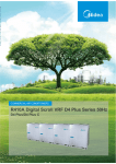
R410A Full DC Inverter V4 Plus
K series Outdoor Unit
Technical Service Manual
(380V~3ph~50Hz)
CONFIDENTIAL
R-410A
HEAT PUMP TYPE DC INVERTER VRF
1.MDV Product Development History............................................................................................2
2.DC Inverter V4+ K Series Introduction......................................................................................2
3.Model Line Up.. ..........................................................................................................................9
4.Units Combination Table............................................................................................................ 10
5.Capacity Range of Indoor Units.............................................................................................11
6.Appearance and model names of Indoor Units.......................................................................12
7.Nomenclature...............................................................................................................................14
Part 2 Selection Procedure .................................................
1 Introduction..... ..............................................................................................................................2
2 Unit selection (Based on cooling load).... ..................................................................................6
Part 3Specification & Performance ....................................
1.Specifications...............................................................................................................................2
2.Dimensions....................................................................................................................................6
3.Piping Diagrams.........................................................................................................................10
4.Electric Characteristics..........................................................................................................12
5.Wiring Diagrams and Field Wiring...........................................................................................13
6.Operation Limits.....................................................................................................................18
7.Capacity Tables.....................................................................................................................19
8.Sound Levels........................................................................................................................54
9.Outdoor Fan performance.........................................................................................................55
10.Accessories...............................................................................................................................56
11.Functional parts and safety devices...................................................................................57
Part 3 Specification & Part 2 Selection
Performance
Procedure
Part 1 General Information ....................................................
Part 1 General
Information
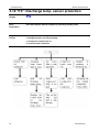
Content
1. Normal Air Conditioner Phenomenon................. ............................. ........................................1
2. Air Conditioner Protection in Common............... ............................. .......................................2
3. Malfunction Code and Troubleshooting............. ............................. ........................................4
Part 6 Electric and Control System ......................................
1. Electric System......................................................................................................2
1.1 Wiring Diagrams and Field Wiring............................................................................................2
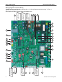
1.2 Description of Main Control Board of Outdoor unit.......... ......................................................2
2. Control System.........................................................................................................................14
2.1 Control System Introduction..................................................................................................14
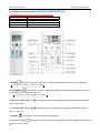
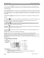
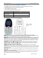
2.2 Wireless Remote Controller......................................................................................................21
2.3 Wired Controller......................................................................................................................29
2.4 Central Control Monitor..........................................................................................................39
2.5 Network Control System.......................................................................................................95
2.6 Other Accessory.....................................................................................................................102
Part 5 Trouble
shooting
Part 5 Troubleshooting ..........................................................
Part 6 Electric and
Control System
1.Installation Introduction...........................................................................................................2
2.Units Installation.....................................................................................................................17
3.Refrigerant Pipe Engineering................................................................................................24
4.Drainage Pipe Engineering....................................................................................................39
5.Duct Engineering....................................................................................................................44
6.Heat Insulation Engineering..................................................................................................47
7.Electrical Engineering............................................................................................................50
8.Commissioning.......................................................................................................................52
Part 4 Installation
Part 4 Installation .................................................................
MCAC-VTSM-2012-09
R410a DC Inverter V4 Plus K Series 50Hz
General Information
1.
MDV Product Development History ........................... 2
2.
DC Inverter V4+ K Series Introduction ...................... 2
3.
Model Line Up .............................................................. 9
4.
Units Combination Table .......................................... 10
5.
Capacity Range of Indoor Units ............................... 11
6.
Appearance and model names of Indoor Units ...... 12
7.
Nomenclature ............................................................. 14
1
Part 1 General
Information
Part 1 General Information
R410a DC Inverter V4 Plus K Series 50Hz
MCAC-VTSM-2012-09
1. MDV Product Development History
In 1999, Midea cooperated with Toshiba, produced the No.1 AC Inverter VRF MDV.
In 2001, Midea produced the No1. MDV in Air-conditioning industry.
In 2002, Midea developed the No.1 AC Inverter VRF MDV, and the No1. D series MDV in China.
In 2003, Midea completed the 2nd D series and 2nd V series MDV.
In 2005, Midea cooperated with Hitachi, produced the No.1 module’s AC Inverter V3 and digital scroll D3.
In 2005, Midea cooperated with IR Company, founded united lab.
In 2008, Midea launched out the MDV4, which is the R410A DC Inverter VRF and Modular design also.
In 2010, the new MDV4+ was on sale, which owns the entirely DC Inverter technology and new low noise
technology.
In 2012, the V4 Plus K series on sale, with the largest capacity up to 72HP.
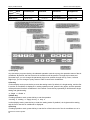
2. DC Inverter V4+ K Series Introduction
2.1 Free combination, The World’s Largest Capacity 72HP
V4+ K series achieved world’s largest capacity of 72HP by combining maximum 4 outdoor units with 6
different capacities. (8, 10, 12, 14, 16 and 18HP), and 64 indoor units can be connected max..
2.2 High efficiency and Energy-saving:
V4+ K Series realized the industry's top class energy efficiency with cooling and heating COP by adoption of
Brushless Reluctance DC compressor control,DC Fan motor and improved heat exchanger performance with
a new design.
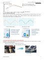
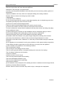
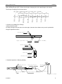
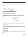
2.2.1 High efficiency DC inverter compressor, saving power 25%
The A/C load ratio of building is 30%-75%, the area use ratio is 55%, most of the A/C runs in the mid load,
so the mid load operation ratio control the whole year AC running charge.
Centralizing winding
2
Distributing winding
General Information
MCAC-VTSM-2012-09
R410a DC Inverter V4 Plus K Series 50Hz
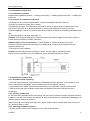
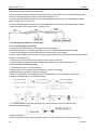
Smooth sine wave DC Inverter
Motor uses 180° sine wave vector drive technology to ensure transducer to output smooth curve, which
show motor rotor speed to run smooth. While, common frequency motor outputs sawtooth wave not to
precisely show motor speed, so its efficiency is low.
Common sawtooth wave
Sine Wave DC inverter
12,14,16,18HP units
adopt a high capacity
DC inverter
compressor and a
fixed compressor
combination
8HP&10HP units adopt
only one DC Inverter
Compressor, offer a
high efficiency and
energy saving solution.
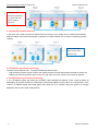
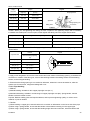
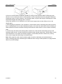
2.2.2 High efficiency DC Fan motor, saving power 50%
According to the running load and pressure, it controls the speed of DC fan to achieve the min. energy
consume, to reach the best effect.
•
•
Used across entire range of models (from 8 to 72 HP).
Efficiency improvement by up to 45% especially at low speed.
Pressure sensor
General Information
DC Fan motor
3
R410a DC Inverter V4 Plus K Series 50Hz
MCAC-VTSM-2012-09
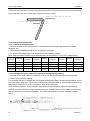
DC Motor fan adopt 18 steps vector speed
adjustment
High Pressure Efficiency-Rotor Speed Curve
Motor rotor speed waves among ±5rpm, and can rapidly match DC Inverter Compressor to output, and
enhance efficiency in part load.
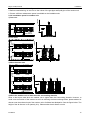
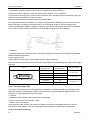
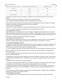
2.2.3 Optimize heat exchange design, Heat exchange efficiency increase 10%
12°C Sub-cooling degree makes the cooling
capacity increased efficiently. Innovative designed
outdoor unit high efficiency heat exchanger, one
time can reach up to 12°C sub-cooling degree,
reduces the system resistance and improves
reliability.
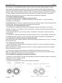
2.3 More flexible design
2.3.1 External static pressure enhanced up to 40 Pa and air volume increase 10%.
Applied high static pressure propeller fan and the
optimum fan guard for high external static pressure, to
respond to a range of various installation environments.
40Pa
Midea now offers up to 40Pa (4.08 mm H2O) external
static pressure specification as an option(0~20Pa as
standard). to meet the requirements of veranda
installation.
* Customization is required.
4
General Information
MCAC-VTSM-2012-09
R410a DC Inverter V4 Plus K Series 50Hz
2.3.2 More options of Indoor units and high capacity connection
Lineup of heat pump types is 8 to 72 HP. Indoor units consist of 14 types with a total of 102 models (not including
Outdoor Air Processing Units), capacity ranges from 1.8kW to 28kW. A maximum 130% indoor unit’s connective
ratio is allowed for all outdoor unit capacities. This wide selection of models makes it possible to build a system that
suits the customer’s requirements.
2.4 High Comfort
2.4.1
Optional outdoor units Silent Mode control
Night silent operation will be activated X (6, 8) hours after the peak temperature during daytime, and it will get
back to normal operation after Y (8,10,12) hours. To run in lower speed, lower noise, min. 46.8dB (A)
2.4.2
More Options for outdoor units
Night silent mode, silence mode, super silence mode.
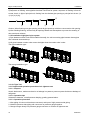
2.5 High Reliability
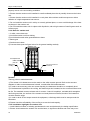
2.5.1 Alternative Cycle Duty operation of outdoor units
V4+ K Series intelligent control, according to the system load, cyclically changes start-up sequence of multiple
outdoor units, equalizes compressor duty and extends operation life-span.
Take 48HP system for example.
General Information
5
R410a DC Inverter V4 Plus K Series 50Hz
MCAC-VTSM-2012-09
Everytime after
oil-returning/defrosting
or restart, ODU will
start in different
sequence
2.5.2 Back-Up operation function
In the event of an outdoor unit fail, the field set back-up function in the outdoor unit in question (also between
different outdoor units) will allow emergency operation of another outdoor unit, in order to maintain the interim
capacity.
Slave 1 ODU failed,
Stops running. Slave
takes the duty
2.5.3 Dynamic gas balance technology
Dynamic vector balance tech., no need to install gas balance pipe:
• High-precision pressure sensor monitors the system pressure on time and transfers the data to master unit
• Master unit sends the pressure date to every unit and make sure each outdoor unit in balance situation.
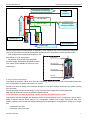
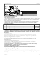
2.5.4 High efficiency oil balance technology
2.10.1 Oil balance pipes set among the modules, and individual oil balance vector control ensures oil
distribution among the modules to compressor smooth and reliable running. When one compressor’s oil is
overfull, oil balance pipes and outlet pipes both send the oil to system, and then system in average
distributes the oil to the other compressors.
6
General Information
MCAC-VTSM-2012-09
R410a DC Inverter V4 Plus K Series 50Hz
Oil balance diagram:
Refrigerant flow direction
Enter
condenser
Oil separator
Discharge pipe
Oil even pipe II
Oil balance pipe
between modules
Oil even pipe I
From evaporator
Suction pipe
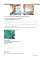
Adopts high efficient centrifugal-type oil separator, which separate the oil from discharged refrigerant
with up to 99% effect to make all the lubricant discharged from compressor can be returned in time.
• New designed low pressure liquid receiver with
high efficiency of oil-return effect.
• Oil balance ensures sufficient refrigerant
lubricant supply. Elaborately designed oil-return
hole, which ensure reliable oil-return for every
compressor.
Suction pipe
Discharge pipe
Oil even pipe
Oil basin
2.5.5 Oil return technology
Centrifugal oil separator can be up to over 99% separating efficiency, which in time and efficiently send the
oil to compressors to ensure compressor oil volume.
System auto back oil design can complete through PC core send oil back instruction by system running
time and state.
The accumulator is large volume design, which can more save refrigerant to avoid liquid strike.
Multi back oil holes can ensure compressor smooth back oil.
2.5.6 Intelligent soft start technology, rapidly enhance refrigerant cycle volume
Compressor soft start complete low frequency and low current start by DC Inv. compressor, and to reduce
strike to electric network. When start DC Inv. Compressor, system runs in large volume and offer more
heating capacity. And use the start rapidly advantage of fixed frequency compressor to quickly up to output
aim.
•
•
Compressor soft start
Lubrication system soft start
General Information
7
R410a DC Inverter V4 Plus K Series 50Hz
MCAC-VTSM-2012-09
2.6 Convenient for installation and service
2.6.1 Auto addressing
Addressing outdoor units and indoor units are automatically done just by pressing the button of the controller.
•
The outdoor unit can automatically distribute the address to indoor units without any manual settings.
•
Wireless controller can enquiry and modify every indoor units address。
•
Up to 64 indoor units can be connected to one system and identified automatically
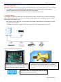
2.6.2 Super Wiring
It is possible to enable the shared use of the wiring between indoor & outdoor units, as well the centralized
control. Hence make it easy for the user to retrofit the existing system with a centralized control, by simply
connecting it to the outdoor units.
PQE & XYE, just only one group of communication wire of PQE, achieved both of communication for indoor
•
& outdoor unit and network.
reversible communication , central controller can connect from indoor side or outdoor side at will
•
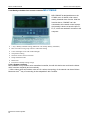
2.6.3 Convenient for maintenance
The high/low pressure valves adopt the Stop Valves, which has screwed
Convenient electronic control check window. Can directly
thread nipple joint, can be connected the Meter connector directly for
observe the operation status from the LED display, and
more convenience in air tight test. And also make more efficient and easy
directly press the FORCE COOLING / CHECK button.
for installation.
Self diagnosis function and four-digit Digital display, help service
engineer to find out the fault fast and easily.
8
General Information
MCAC-VTSM-2012-09
R410a DC Inverter V4 Plus K Series 50Hz
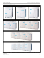
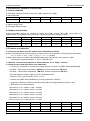
3. Model Line Up
Outdoor units (Combination Unit):
8, 10 HP
12 ,14 ,16 HP
18, 20, 22, 24, 26, 28, 30, 32 HP
18HP
34, 36, 38, 40, 42, 44, 46, 48 HP
50, 52, 54, 56, 58, 60, 62, 64 HP
66, 68, 70, 72 HP
*18HP model will be available at the end for 2012.The above recommended combination pattern will be changed
at that time.
General Information
9
R410a DC Inverter V4 Plus K Series 50Hz
MCAC-VTSM-2012-09
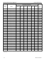
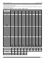
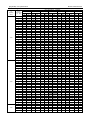
4. Units Combination Table
Max.
Recommend combination
Capacity
indoor
Model
(HP)
8(HP)
10(HP)
12(HP)
14(HP)
16(HP)
18(HP)
units
nos.
8
MDV-252(8)W/DRN1(C)
10
MDV-280(10)W/DRN1(C)
12
MDV-335(12)W/DRN1(C)
14
MDV-400(14)W/DRN1(C)
16
MDV-450(16)W/DRN1(C)
18
MDV-532(18)W/DRN1(C)
20
13
16
20
23
26
29
MDV-560(20)W/DRN1(C)
33
22
MDV-615(22)W/DRN1(C)
24
MDV-680(24)W/DRN1(C)
26
MDV-730(26)W/DRN1(C)
28
MDV-785(28)W/DRN1(C)
30
MDV-850(30)W/DRN1(C)
32
MDV-900(32)W/DRN1(C)
34
MDV-960(34)W/DRN1(C)
36
MDV-1010(36)W/DRN1(C)
38
MDV-1065(38)W/DRN1(C)
40
MDV-1130(40)W/DRN1(C)
42
MDV-1180(42)W/DRN1(C)
44
MDV-1235(44)W/DRN1(C)
64
46
MDV-1300(46)W/DRN1(C)
64
48
MDV-1350(48)W/DRN1(C)
64
50
MDV-1432(50)W/DRN1(C)
64
52
MDV-1460(52)W/DRN1(C)
64
54
MDV-1515(54)W/DRN1(C)
64
56
MDV-1580(56)W/DRN1(C)
64
58
MDV-1630(58)W/DRN1(C)
64
60
MDV-1685(60)W/DRN1(C)
64
62
MDV-1750(62)W/DRN1(C)
64
64
MDV-1800(64)W/DRN1(C)
64
66
MDV-1931(66)W/DRN1(C)
68
MDV-1996(68)W/DRN1(C)
70
MDV-2046(70)W/DRN1(C)
72
MDV-2128(72)W/DRN1(C)
36
39
43
46
50
53
56
59
63
64
64
64
64
64
64
*18HP model will be available at the end for 2012.The above recommended combination pattern will be changed
at that time.
10
General Information
MCAC-VTSM-2012-09
R410a DC Inverter V4 Plus K Series 50Hz
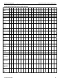
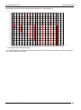
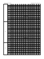
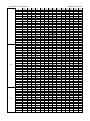
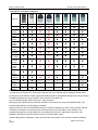
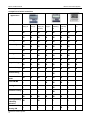
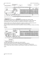
5. Capacity Range of Indoor Units
Power supply of all the indoor units is 1 phase, 220-240V
Capacity (kW)
2.2
2.8
3.6
4.5
5.6
7.1
8
9
10
11.2
12.5
14
16
20
25
28
40
45
56
75
96
123
154
191
242
273
307
341
382
426
478
546
682
853
955
1365
1535
1911
00
00
00
00
00
00
00
00
00
00
00
00
00
00
00
00
00
00
00
Ton
0.6
0.8
1
1.3
1.6
2
2.3
2.6
2.9
3.2
3.5
4
5
5.7
7.1
8
11
12.3
15.4
HP
0.8
1
1.25
1.6
2
2.5
2.8
3.2
3.6
4
4.4
5
6
8
9
10
14
15.7
19.6
INDEX
22
28
36
45
56
71
80
90
100
112
123
140
160
200
250
280
400
450
560
√
√
√
√
√
√
√
√
√
√
√
√
√
√
√
√
√
√
√
√
√
√
√
√
√
√
√
√
√
√
√
√
√
√
√
√
√
√
√
√
√
√
√
√
√
√
√
√
√
√
√
√
√
√
√
√
√
√
√
√
√
√
√
√
√
BTU/H
One-way
Cassette
Two- way
Cassette
Compact
Four- way
Cassette
Four-way
Cassette Type
Low Static
Pressure Duct
Ductable Unit
A5 Type
High Static
Pressure Duct
Ceiling &
√
√
√
Floor
Wall-mounted
√
√
√
√
√
√
√
√
√
√
-S Type
Wall-mounted
-C Type
Wall-mounted
-R Type
Console
√
√
√
√
√
√
√
√
√
√
√
√
√
√
√
√
√
√
√
√
√
√
√
√
√
Concealed
Floor-standin
g
Exposed
Floor-standin
g
Exposed
Floor-standin
g(New panel)
Fresh Air
processing
√
√
Unit
General Information
11
R410a DC Inverter V4 Plus K Series 50Hz
MCAC-VTSM-2012-09
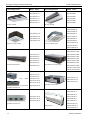
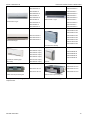
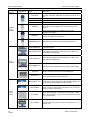
6. External Appearance and model names of Indoor Units
External Appearance
Model
Name
External Appearance
Model
Name
MDV-D28Q1/N1-C
MDV-D22Q2/N1
MDV-D36Q1/N1-C
MDV-D28Q2/N1
MDV-D45Q1/N1-C
MDV-D36Q2/N1
MDV-D56Q1/N1-C
MDV-D45Q2/N1
MDV-D71Q1/N1-C
MDV-D56Q2/N1
One-way cassette
Two-way cassette
MDV-D28Q4/N1-D
MDV-D36Q4/N1-D
MDV-D45Q4/N1-D
MDV-D22Q4/N1-A3
MDV-D56Q4/N1-D
MDV-D28Q4/N1-A3
MDV-D71Q4/N1-D
MDV-D36Q4/N1-A3
MDV-D80Q4/N1-D
MDV-D45Q4/N1-A3
MDV-D90Q4/N1-D
Four-way Cassette Type
Compact four-way cassette
MDV-D100Q4/N1-D
MDV-D112Q4/N1-D
MDV-D140Q4/N1-D
MDV-D22T2/N1X-BA5
MDV-D28T2/N1X-BA5
MDV-D18T3/N1-B
MDV-D36T2/N1X-BA5
MDV-D22T3/N1-B
MDV-D45T2/N1X-BA5
MDV-D28T3/N1-B
MDV-D56T2/N1X-BA5
MDV-D36T3/N1-B
MDV-D71T2/N1X-BA5
MDV-D45T3/N1-B
Low Static Pressure Duct
MDV-D56T3/N1-B
Concealed Duct Unit (A5 Type)
MDV-D80T2/N1X-BA5
MDV-D90T2/N1X-BA5
MDV-D112T2/N1X-BA5
MDV-D140T2/N1X-BA5
MDV-D71T1/N1-B
MDV-D80T1/N1-B
71~112
Model
MDV-D200T1/N1-B
MDV-D90T1/N1-B
MDV-D250T1/N1-B
MDV-D112T1/N1-B
MDV-D140T1/N1-B
140~160 Model
MDV-D160T1/N1-B
MDV-D280T1/N1-B
High Static Pressure Duct
High Static Pressure Duct
MDV-D36DL/N1-C
MDV-D45DL/N1-C
MDV-D56DL/N1-C
MDV-D400T1/N1-B
MDV-D71DL/N1-C
MDV-D450T1/N1-B
MDV-D80DL/N1-C
MDV-D560T1/N1-B
MDV-D90DL/N1-C
High Static Pressure Duct
MDV-D112DL/N1-C
Ceiling & Floor
MDV-D140DL/N1-C
MDV-D160DL/N1-C
12
General Information
MCAC-VTSM-2012-09
Wall-mounted -S Type
R410a DC Inverter V4 Plus K Series 50Hz
MDV-D22G/N1-S
MDV-D22G/N1-S
MDV-D22G/DN1-S
MDV-D22G/DN1-S
MDV-D28G/N1-S
MDV-D28G/N1-S
MDV-D28G/DN1-S
MDV-D28G/DN1-S
MDV-D36G/N1-S
MDV-D36G/N1-S
MDV-D36G/DN1-S
MDV-D36G/DN1-S
MDV-D45G/N1-S
Wall-mounted -C Type
MDV-D45G/N1-S
MDV-D45G/DN1-S
MDV-D45G/DN1-S
MDV-D56G/N1-S
MDV-D56G/N1-S
MDV-D56G/DN1-S
MDV-D56G/DN1-S
MDV-D22Z/N1-F3B
MDV-D28Z/N1-F3B
Wall-mounted R type
MDV-D71G-R3/N1Y
MDV-D36Z/N1-F3B
MDV-D80G-R3/N1Y
MDV-D45Z/N1-F3B
MDV-D90G-R3/N1Y
MDV-D56Z/N1-F3B
MDV-D71Z/N1-F3B
Concealed floor standing
MDV-D80Z/N1-F3B
MDV-D22Z/N1-F4(F5)
MDV-D28Z/N1-F4(F5)
MDV-D22Z/DN1-B
MDV-D36Z/N1-F4(F5)
MDV-D28Z/DN1-B
MDV-D45Z/N1-F4(F5)
MDV-D36Z/DN1-B
MDV-D56Z/N1-F4(F5)
Exposed floor standing Type
MDV-D71Z/N1-F4(F5)
(New Panel)
MDV-D80Z/N1-F4(F5)
MDV-D45Z/DN1-B
Console
MDV-D200T1/N1-FA
Outdoor fresh air-processing unit
MDV-D125T1/N1-FA
MDV-D250T1/N1-FA
MDV-D140T1/N1-FA
MDV-D280T1/N1-FA
Outdoor fresh air-processing unit
The specifications, designs, and information in this book are subject to change without notice for product improvement. General Information
13
R410a DC Inverter V4 Plus K Series 50Hz
MCAC-VTSM-2012-09
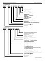
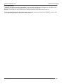
7. Nomenclature
7.1 Outdoor unit:
MDV – 252 (8) W / D R N1 i (C)
Design Serial Number
(C): K Series
i: Individual Module
Omit: Combinable Module
Refrigerant type
N1:R410A
Omit for R22
Power Supply
R: 380~415V, 50Hz, 3N
Inverter Type
D: DC Inverter Omit for AC Inverter
Outdoor Unit
Rated Capacity (HP), (only for combinable type)
Cooling Capacity (×100W)
Midea VRF
7.2 Indoor unit:
MDV – D 28 Z / D D N1 A
Design Serial Number & Improved code
Such as A1, A2, B1, B2, C, D, etc.
Refrigerant type
N1:R410A
Omit for R22
Electrical Auxiliary Heater
D: with EAH
Omit for without EAH
Motor Type
D: DC Fan Motor
Omit for AC fan Motor
Indoor Unit Structural category
Q4: Standard four way cassette
Q4-A: Compact four way cassette
Q2: Two way cassette
T1: High Static Pressure Unit
T2: Middle Static Pressure Unit, such as T2-A3, T2-A5
T3: Low Static Pressure Unit,
DL: Ceiling & Floor Type
G: Wall mounted Type, such as G-S, G-C, etc.
Z: Floor Standing (Z-F4, Z-F5: Exposed /Z-F3: Concealed)
Cooling Capacity (×100W)
VRF Indoor Unit
Midea VRF
14
General Information
MCAC-VTSM-2012-09
Selection Procedure
Part 2
Selection Procedure
1 Introduction ......................................................................... 2
Part 2 Selection
Procedure
2 Unit selection (Based on cooling load) ............................. 6
Selection Procedure
1
Selection Procedure
MHVAC-VTSM-2010-03
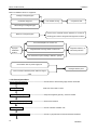
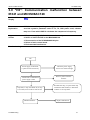
1. Introduction
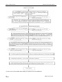
1.1 Model Selection Procedure
Select the model and calculate the capacity for each refrigerant system according to the procedure shown
below.
-conditioning load, Calculate the maximum air-conditioning load for each
room or zone.
Selection of an air conditioning system
Design of the control system
Design a suitable control system for the selected air conditioning system
Preliminary selection of indoor and outdoor units
Make preliminary selections that are within the allowable range for the system
Check of the tubing length and elevation difference
● Check that the length of refrigerant tubing and the elevation difference are within the allowable ranges
Calculation of the corrected outdoor unit capacity
●Capacity correction coefficient for model, outdoor temperature conditions, tubing length and elevation
difference.
Calculation of the actual capacity for each indoor unit
●Calculate the corrected indoor/outdoor capacity ratio, based on the corrected outdoor unit capacity and
the total corrected capacity of all indoor units in the same system.
Recheck of the actual capacity for each indoor unit
●If the capacity is inadequate, reexamine the unit combinations.
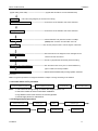
1.2 Indoor Unit Selection
Enter INDOOR UNIT CAPACITY TABLES at given indoor and outdoor temperature. Select the unit that
the capacity is the nearest to and greater than given load.
Note:
Individual indoor unit capacity is subject to change by the combination. Actual capacity has to be calculated according to the
combination by using outdoor unit capacity table.
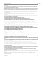
1.2.1 Calculation of Actual Capacity of Indoor Unit
Because the capacity of a multi air-conditioner changes according to the temperature conditions, tubing
length, elevation difference and other factors, select the correct model after taking into account the various
correction values. When selecting The model, calculate the corrected capacities of the outdoor unit and
each indoor unit. Use the corrected outdoor unit capacity and the total corrected capacity of all the indoor
units to calculate the actual final capacity of each indoor unit.
Find the indoor unit capacity correction coefficient for the following items
Capacity correction for the indoor unit temperature conditions
From the graph of capacity characteristics, use the indoor temperature to find the capacity correction coefficient.
Capacity distribution ratio based on the indoor unit tubing length and elevation difference.
First, in the same way as for the outdoor unit, use the tubing length and elevation difference for each indoor
unit to find the correction coefficient from the graph of capacity change characteristics
Capacity distribution ratio for each indoor unit = Correction coefficient for that indoor unit / Correction coefficient for the outdoor
unit
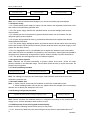
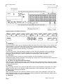
1.3 Outdoor Unit Selection
Allowable combinations are indicated in INDOOR UNIT COMBINATION TOTAL CAPACITY INDEX
TABLE.
In general, outdoor unit can be selected as follows though the location of the unit, zoning and usage of the
rooms may be considered.
The indoor and outdoor unit combination is determined that the sum of indoor unit capacity index is
2
Selection Procedure
MCAC-VTSM-2011-09
Selection Procedure
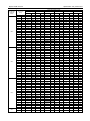
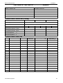
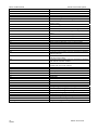
nearest to and smaller than the capacity index at 100% combination ratio of each outdoor unit. Up to 8~16
indoor units can be connected to one outdoor unit. It is recommended to choose a larger outdoor unit if the
installation space is large enough.
If the combination ratio is greater than 100%, the indoor unit selection shall be reviewed by using actual
capacity of each indoor unit.
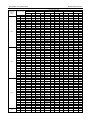
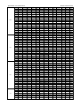
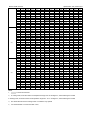
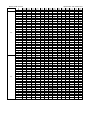
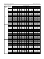
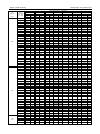
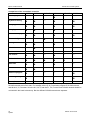
INDOOR UNIT COMBINATION TOTAL CAPACITY INDEX TABLE
Outdoor Unit
Indoor Unit Combination Ratio (kW)
130%
120%
110%
100%
90%
80%
70%
60%
50%
8HP
32.8
30.2
27.7
25.2
22.7
20.1
17.6
15.1
12.6
10HP
36.4
33.6
30.8
28.0
25.2
22.4
19.6
16.8
14.0
12HP
43.6
40.2
36.9
33.5
30.2
26.8
23.5
20.2
16.8
14HP
52.0
48.0
44.0
40.0
36.0
32.0
28.0
24.0
20.0
16HP
58.5
54.0
49.5
45.0
40.5
36.0
31.5
27.0
22.5
18HP
69.2
63.8
58.5
53.2
47.9
42.6
37.2
31.9
26.6
20HP
72.8
67.2
61.6
56.0
50.4
44.8
39.2
33.6
28.0
22HP
80.0
73.8
67.7
61.5
55.4
49.2
43.1
36.9
30.8
24HP
88.4
81.6
74.8
68.0
61.2
54.4
47.6
40.8
34.0
26HP
94.9
87.6
80.3
73.0
65.7
58.4
51.1
43.8
36.5
28HP
102.1
94.2
86.4
78.5
70.7
62.8
55.0
47.1
39.3
30HP
110.5
102.0
93.5
85.0
76.5
68.0
59.5
51.0
42.5
32HP
117.0
108.0
99.0
90.0
81.0
72.0
63.0
54.0
45.0
34HP
124.8
115.2
105.6
96.0
86.4
76.8
67.2
57.6
48.0
36HP
131.3
121.2
111.1
101.0
90.9
80.8
70.7
60.6
50.5
38HP
138.5
127.8
117.2
106.5
95.9
85.2
74.6
63.9
53.3
40HP
146.9
135.6
124.3
113.0
101.7
90.4
79.1
67.8
56.5
42HP
153.4
141.6
129.8
118.0
106.2
94.4
82.6
70.8
59.0
44HP
160.6
148.2
135.9
123.5
111.2
98.8
86.5
74.1
61.8
46HP
169.0
156.0
143.0
130.0
117.0
104.0
91.0
78.0
65.0
48HP
175.5
162.0
148.5
135.0
121.5
108.0
94.5
81.0
67.5
50HP
186.2
171.8
157.5
143.2
128.9
114.6
100.2
85.9
71.6
52HP
189.8
175.2
160.6
146.0
131.4
116.8
102.2
87.6
73.0
54HP
197.0
181.8
166.7
151.5
136.4
121.2
106.1
90.9
75.8
56HP
205.4
189.6
173.8
158.0
142.2
126.4
110.6
94.8
79.0
58HP
211.9
195.6
179.3
163.0
146.7
130.4
114.1
97.8
81.5
60HP
219.1
202.2
185.4
168.5
151.7
134.8
118.0
101.1
84.3
62HP
227.5
210.0
192.5
175.0
157.5
140.0
122.5
105.0
87.5
64HP
234.0
216.0
198.0
180.0
162.0
144.0
126.0
108.0
90.0
66HP
251.0
231.7
212.4
193.1
173.8
154.5
135.1
115.9
96.6
68HP
259.5
239.5
219.6
199.6
179.6
159.7
139.7
119.8
99.8
70HP
266.0
245.5
225.1
204.6
184.1
163.7
143.2
122.8
102.3
72HP
276.6
255.4
234.1
212.8
191.5
170.2
148.9
127.7
106.4
INDOOR UNIT CAPACITY INDEX
Unit Size
Model
18
Model
22
Model
28
Model
36
Model
45
Model
56
Model
71
Model
80
Model
90
Model
112
Capacity Index (kW)
1.8
2.2
2.8
3.6
4.5
5.6
7.1
8.0
9.0
11.2
Unit Size
Model
140
Model
160
Model
200
Model
250
Model
280
Capacity Index (kW)
14.0
16
20
25
28
Selection Procedure
3
Selection Procedure
MHVAC-VTSM-2010-03
1.3 Actual Performance Date
Use OUTDOOR UNIT CAPACITY TABLES.
Determine correct table according to the outdoor unit model and combination ratio.
Enter the table at given indoor and outdoor temperature and find the outdoor unit capacity and power input.
The individual indoor unit capacity (power input) can by calculated as follows.
IUC=OUC × INX/TNX
Where,
IUC: Each indoor unit capacity
OUC: Outdoors unit capacity
INX: Each indoor unit capacity index
TNX: Total capacity index
Then, correct the indoor unit capacity according to the piping length.
If the corrected capacity is smaller than the load, the size of indoor unit has to be increased and repeat the
same selection procedure.
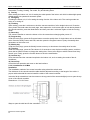
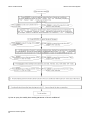
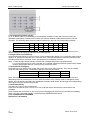
1.4 Variation in capacity in accordance with the length of refrigerant pipe
1.4.1 Cooling capacity modification
Modification coefficient of the length and high difference of refrigerant pipe:
H(m)
70
60
50
40
30
0
83
85
87
89
92
94
97
99
100%
20
10
-10
-20
-30
-40
-50
-60
-70
-80
-90
-100
-110
10
20
30
40
50
60
70
80
90
100 110 120 130 140 150 160 170 180
190
200 L(m)
L: Refrigerant pipe equivalent length
H: Height difference between outdoor and indoor unit. Positive data means outdoor unit is top. Negative
data means outdoor unit is down.
4
Selection Procedure
MCAC-VTSM-2011-09
Selection Procedure
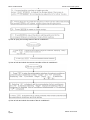
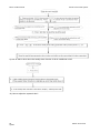
1.4.2 Heating capacity modification
Modification coefficient of the length and high difference of refrigerant pipe:
H(m)
70
60
50
40
30
20
93
95
96
97
98
99
0
100%
10
-10
-20
-30
-40
-50
-60
-70
-80
-90
-100
-110
10
20
30
40
50
60
70
80
90
100 110 120 130 140 150 160 170 180
190
200
L(m)
L: Refrigerant pipe equivalent length
H: Height difference between outdoor and indoor unit. Positive data means outdoor unit is top. Negative
data means outdoor unit is down.
Selection Procedure
5
Selection Procedure
MHVAC-VTSM-2010-03
2 Unit Selection (Based on cooling load)
2.1 Given condition
2.1.1 Design condition (Cooling: Indoor 20°C (WB), Outdoor 35°C (DB))
2.1.2 Cooling load
Location
Room A
Room B
Room C
Room D
Room E
Room F
Load (kW)
2.1
2.8
3.5
4.6
5.8
7.2
2.1.3 Power supply unit: Outdoor 380~415V-3Ph-50Hz, Indoor 220~240V-1Ph-50Hz.
2.1.4 Pipe length: 50m
2.1.5 Height difference: 30m
2.2 Indoor unit selection
Select the suitable capacity for condition of ‘Indoor 20°C (WB), Outdoor 35°C (DB)’ using indoor unit
capacity table. The selected result is as follows. (Assuming the indoor unit type is duct)
Location
Room A
Room B
Room C
Room D
Room E
Room F
Load (kW)
2.1
2.8
3.5
4.6
5.8
7.2
Unit size
22
28
36
45
56
71
Capacity (kW)
2.3
2.9
3.7
4.8
6.0
7.5
2.3 Outdoor unit selection
2.3.1 Assume the indoor unit and outdoor unit combination as follows
2.3.1.1 Calculate the total nominal capacity of indoor units in the combination according to the above table:
2.2 × 1 +2.8 × 1+ 3.6 × 1 +4.5 × 1+ 5.6 × 1 + 7.1 × 1 = 25.8kW
2.3.1.2 Select outdoor unit: MDV-280(10)W/DRN1(B) which has nominal cooling capacity: 28kW.
Calculate the proportion between ① and ②: 258/280= 92%
2.3.2 Result : Because the proportion is within 50~130%, it is a ”Right” selection.
2.3.3 Real function data with indoor unit combination
● For the 92% combination, calculate the cooling capacity of outdoor unit (MDV-280(10)W/DRN1(B)).
26.65KW ←90% (Indoor temperature : WB 20°C, Outdoor temperature: DB 35°C)
29.61KW ←100%(Indoor temperature : WB 20°C, Outdoor temperature: DB 35°C)
Then calculated the outdoor capacity in 92% combination index:
Therefore: 26.65+ {(29.61-26.65)/ 10} ×2= 27.24;
● Outdoor unit (MDV-280(10)W/DRN1(C)) cooling temperature: DB 35°C
● Capacity modification coefficient with pipe length (50m) and height difference (30m): 0.958
● Each indoor unit cooling capacity
MDV-D22T2: 27.24 × 22/258 × 0.958 = 2.22(kW)
MDV-D28T2: 27.24 × 28/258 ×0.958 = 2.83 (kW)
MDV-D36T2: 27.24 × 36/258 ×0.958 = 3.64 (kW)
MDV-D45T2: 27.24 × 45/258 ×0.958 = 4.55 (kW)
MDV-D56T2: 27.24 × 56/258 ×0.958 = 5.66 (kW)
MDV-D71T2: 27.24 × 71/258 ×0.958 = 7.18 (kW)
6
Location
Room A
Room B
Room C
Room D
Room E
Room F
Load (kW)
2.1
2.8
3.5
4.6
5.8
7.2
Unit size
22
28
36
45
56
71
Capacity (kW)
2.22
2.83
3.64
4.55
5.66
7.18
Selection Procedure
MCAC-VTSM-2011-09
Selection Procedure
2.4 Conclusion
Generally, we think this result is acceptable, so we can think we have accomplished the calculation. But if
you think this result is not acceptable, you can repeat the above process.
Remark: In this sample, we don’t consider the other capacity modification index and assume them are 1.0.
For more details about the effect factor such as outside ambient/inside ambient DB/WD , please refer
to the performance table of indoor and outdoor units.
Selection Procedure
7
MCAC-VTSM-2012-09
Specification and performance
Part 3 Specification & Performance
1. Specifications ................................................................. 2
2. Dimensions ..................................................................... 6
3. Piping Diagrams ........................................................... 10
5. Wiring Diagrams and Field Wiring .............................. 13
6. Operation Limits ........................................................... 18
7. Capacity Tables ............................................................. 19
8. Sound Levels ................................................................ 54
9. Outdoor Fan performance............................................ 55
10. Accessories ................................................................. 56
11. Functional parts and safety devices ......................... 57
Specification and performance
1
Part 3 Specification
& Performance
4. Electric Characteristics ................................................ 12
Specification and performance
MCAC-VTSM-2012-09
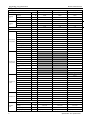
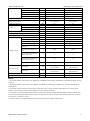
1. Specifications
Factory model
Power supply
Cooling
(*1)
Heating
(*2)
V-Ph-Hz
MDV-280(10)W/DRN1(C)
MDV-335(12)W/DRN1(C)
380~415V 3Ph ~ 50Hz
380~415V 3Ph ~ 50Hz
380~415V 3Ph ~ 50Hz
Capacity
W
25200
28000
33500
Input
W
5875
7198
9054
EER
W/W
4.29
3.89
3.7
Capacity
W
27000
31500
37500
Input
W
6150
7609
8993
COP
W/W
Max. input consumption
W
Max. current
A
4.39
4.14
4.17
11270
11270
12864
20.8
22.1
23.7
E655DHD-65D2YG
E655DHD-65D2YG
E405DHD-36D2YG
1
1
1
Type
DC Inverter
DC Inverter
DC Inverter
Brand
Hitachi
Hitachi
Hitachi
Model
Quantities
DC Inverter
compressor
MDV-252(8)W/DRN1(C)
Capacity
W
31590
31590
11800
Input
W
10340
10340
3665
Power supply
380-415V~3Ph, 50Hz
380-415V~3Ph, 50Hz
380-415V~3Ph, 50Hz
Operating frequency
V-Ph-Hz
Hz
40~200
40~200
60~180
Crankcase
W
27.6+27.6
27.6+27.6
27.6
Refrigerant oil
ml
FVC68D / 500
FVC68D / 500
Model
Quantities
1
Type
Fixed scroll
Brand
Hitachi
Capacity
Fixed scroll
compressor
W
Input
Power supply
17100
W
5740
V-Ph-Hz
Locked rotor ampere
(LRA)
380-415V~3Ph, 50Hz
A
68
Thermal protector type
Inner
Crankcase
W
27.6
Refrigerant oil
ml
FVC68D / 500
Model
WZDK750-38G-4
WZDK750-38G-4
WZDK560-38G(A)/YDK38
0-4D-1
Brand
Panasonic
Panasonic
Panasonic
1
1
1+1
Quantities
Insulation class
Outdoor fan
motor
Safe class
E
IPX4
W
465
465
465+640
W
750
750
560+380
A
3.6
3.6
3.6+2.94
r/min
800
800
800+1060
Plastic
Plastic
Plastic
Axial
Axial
Axial
1
1
2
material
Type
Fan Quantities
Dimension(Dia.×H)
700*202
700*202
560*189
Vane Quantities of each blower
3
3
3/4
Number of rows
2
2
2
mm
Tube pitch(a)x row
pitch(b)
mm
22×19.05
22×19.05
22×19.05
Fin spacing
mm
1.6
1.6
1.6
Hydrophilic aluminum
Hydrophilic aluminum
Hydrophilic aluminum
Fin type (code)
2
E
IPX4
Output
Speed
Outdoor
coil
E
IPX4
Input
Rated current
Outdoor fan
FVC68D / 500
E655DH-65D2YG(GC)
Specification and performance
MCAC-VTSM-2012-09
Tube outside dia.
Tube
Specification and performance
mm
type
Coil length x height
mm
Number of circuits
Outdoor air flow
External static pressure
Outdoor sound level (*3)
Outdoor
unit
3
m /h
Pa
Ф7.94
Inner-grooved
1985*1232
1985*1232
2270*1232
22
22
22
11500
11500
15100
0~20 (default)
0~20 (default)
0~20 (default)
20~40 (optional)
20~40 (optional)
20~60 (optional)
57
57
59
mm
960*1615*765
960*1615*765
1250*1615*765
Packing (W*H*D)
mm
1025*1790*830
1025*1790*830
1310*1790*825
Kg
198/213
198/213
268/288
kg
R410A 9kg
R410A 9kg
R410A 11kg
EXV
EXV
EXV
MPa
4.4/2.6
4.4/2.6
4.4/2.6
Liquid side/ Gas side
(*4)
mm
Ф12.7/Ф25.4
Ф12.7/Ф25.4
Ф12.7/Ф25.4
Oil balance pipe
mm
Ф6.35
Ф6.35
Ф6.35
Total pipe length
m
1000
1000
1000
m
175
175
175
200
200
Charged refrigerant type and volume
Throttle type
Excessive operating pressure
The farthest pipe
length(actual)
The farthest pipe length
(equivalent)
Refrigerant
piping
Ф7.94
Inner-grooved
Dimension(W*H*D)
Net/Gross weight
dB(A)
Ф7.94
Inner-grooved
m
200
The farthest equivalent
pipe length from the 1st
distributor (*5)
m
40/90
40/90
40/90
Max. Vertical pipe length
(When outdoor units is
top)
m
70
70
70
Max. Vertical pipe length
(When outdoor units is
bottom)
m
110
110
110
Max. drop between indoor
units
m
30
30
30
4×10+10(L≤20m);
4×10+10(L≤20m);
4×10+10(L≤20m);
4×16+10(L≤50m)
4×16+10(L≤50m)
4×16+10(L≤50m)
3 core shielded wiring;
3 core shielded wiring;
3 core shielded wiring;
wiring dia.≥0.75
wiring dia.≥0.75
wiring dia.≥0.75
Power wiring
mm2
Signal wiring
mm2
Connection
wiring
Ambient temp. range - Cooling
℃
-5℃-48℃
-5℃-48℃
-5℃-48℃
Ambient temp. range - Heating
℃
-20℃-21℃
-20℃-21℃
-20℃-21℃
Notes:
1. The cooling conditions: indoor temp.: 27℃ DB(80.6℉), 19℃WB(60℉) outdoor temp.: 35℃DB(95℉)
equivalent pipe length: 5m drop
length: 0m.
2. The heating conditions: indoor temp.: 20℃ DB(68℉), 15℃WB(44.6℉) outdoor temp.: 7℃DB(42.8℉)
equivalent pipe length: 5m
drop length: 0m.
3. Sound level: Anechoic chamber conversion value, measured at a point 1 m in front of the unit at a height of 1.5 m. During actual
operation, these values are normally somewhat higher as result of ambient conditions.
4. It’s dimension of connecting pipes between outdoor and first branch joint when the Max. Equivalent length of tubing is less than 90m.
5. The farthest equivalent pipe length should be equal to or shorter than 40m, But it can be up to 90m if meet the required conditions
following part 4 installation section
6. The above data may be changed without notice for future improvement on quality and performance.
Specification and performance
3
Specification and performance
MCAC-VTSM-2012-09
Factory model
Power supply
Cooling
Heating
(*1)
(*2)
V-Ph-Hz
MDV-400(14)W/DRN1(C)
MDV-450(16)W/DRN1(C)
380~415V 3Ph ~ 50Hz
380~415V 3Ph ~ 50Hz
Capacity
W
40000
45000
Input
W
12308
14019
EER
W/W
3.25
3.21
Capacity
W
45000
50000
Input
W
11194
12787
COP
W/W
4.02
3.91
Max. input consumption
W
16530
18486
Max. current
A
31.8
32.8
E655DHD-65D2YG
E655DHD-65D2YG
1
1
Type
DC Inverter
DC Inverter
Brand
Hitachi
Hitachi
Model
Quantities
DC Inverter
compressor
Capacity
W
31590
31590
Input
W
10340
10340
380-415V~3Ph, 50Hz
380-415V~3Ph, 50Hz
Power supply
V-Ph-Hz
Operating frequency
Hz
40~200
40~200
Crankcase
W
27.6+27.6
27.6+27.6
Refrigerant oil
ml
Model
Quantities
Type
Brand
Capacity
Fixed scroll
compressor
Input
Power supply
Locked rotor ampere (LRA)
W
W
V-Ph-Hz
A
Thermal protector type
Hitachi
Hitachi
15390
17100
5130
5740
380-415V~3Ph, 50Hz
380-415V~3Ph, 50Hz
62
68
Inner
Inner
W
27.6
27.6
FVC68D / 500
FVC68D / 500
Model
WZDK560-38G(A)/YDK380-4D-1
WZDK560-38G(A)/YDK380-4D-1
Brand
Panasonic
Panasonic
1+1
1+1
Safe class
E
E
IPX4
IPX4
Input
W
465+640
465+640
Output
W
560+380
560+380
Rated current
A
3.6+2.94
3.6+2.94
r/min
800+1060
800+1060
Plastic
Plastic
Axial
Axial
2
2
560*189
560*189
Vane Quantities of each blower
3/4
3/4
Number of rows
2
2
material
Type
Fan Quantities
Dimension(Dia.×H)
4
1
Fixed scroll
ml
Speed
Outdoor coil
1
Fixed scroll
Refrigerant oil
Insulation class
Outdoor fan
FVC68D / 500
E655DH-65D2YG(GC)
Crankcase
Quantities
Outdoor fan motor
FVC68D / 500
E605DH-59D2YG
mm
Tube pitch(a)x row pitch(b)
mm
22×19.05
22×19.05
Fin spacing
mm
1.6
1.6
Specification and performance
MCAC-VTSM-2012-09
Specification and performance
Fin type (code)
Tube outside dia.
Tube
mm
type
Coil length x height
External static pressure
Outdoor unit
Inner-grooved
2270*1232
2270*1232
22
22
m3/h
15100
15100
0~20 (default)
0~20 (default)
20~40 (optional)
20~40 (optional)
60
60
dB(A)
Dimension(W*H*D)
mm
1250*1615*765
1250*1615*765
Packing (W*H*D)
mm
1310*1790*825
1310*1790*825
Net/Gross weight
Charged refrigerant type and volume
Kg
280/300
280/300
kg
R410A 13kg
R410A 13kg
EXV
EXV
Throttle type
Excessive operating pressure
MPa
4.4/2.6
4.4/2.6
mm
Ф15.9/Ф31.8
Ф15.9/Ф31.8
Oil balance pipe
mm
Ф6.35
Ф6.35
Total pipe length
m
1000
1000
The farthest pipe length(actual)
m
175
175
The farthest pipe length
(equivalent)
m
200
The farthest equivalent pipe
length from the 1st distributor
(*5)
m
40/90
40/90
Max. Vertical pipe length (When
outdoor units is top)
m
70
70
Max. Vertical pipe length (When
outdoor units is bottom)
m
110
110
Max. drop between indoor units
m
30
30
4×16+16(L≤20m);
4×16+16(L≤20m);
Liquid side/ Gas side
Refrigerant piping
Ф7.94
Inner-grooved
Pa
Outdoor sound level (*3)
Hydrophilic aluminum
Ф7.94
mm
Number of circuits
Outdoor air flow
Hydrophilic aluminum
Power wiring
(*4)
mm2
Connection wiring
Signal wiring
mm2
200
4×25+16(L≤50m)
4×25+16(L≤50m)
3 core shielded wiring;
3 core shielded wiring;
wiring dia.≥0.75
wiring dia.≥0.75
Ambient temp. range - Cooling
℃
-5℃-48℃
-5℃-48℃
Ambient temp. range - Heating
℃
-20℃-21℃
-20℃-21℃
Notes:
1. The cooling conditions: indoor temp.: 27℃ DB(80.6℉), 19℃WB(60℉) outdoor temp.: 35℃DB(95℉)
equivalent pipe length: 5m drop
length: 0m.
2. The heating conditions: indoor temp.: 20℃ DB(68℉), 15℃WB(44.6℉) outdoor temp.: 7℃DB(42.8℉)
equivalent pipe length: 5m
drop length: 0m.
3. Sound level: Anechoic chamber conversion value, measured at a point 1 m in front of the unit at a height of 1.5 m. During actual
operation, these values are normally somewhat higher as result of ambient conditions.
4. It’s dimension of connecting pipes between outdoor and first branch joint when the Max. Equivalent length of tubing is less than 90m.
5. The farthest equivalent pipe length should be equal to or shorter than 40m, But it can be up to 90m if meet the required conditions
following part 4 installation section
6. The above data may be changed without notice for future improvement on quality and performance.
Specification and performance
5
Specification and performance
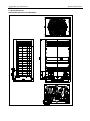
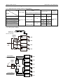
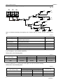
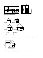
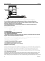
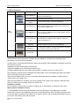
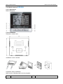
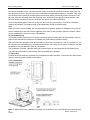
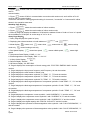
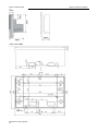
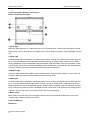
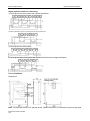
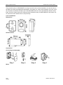
2. Dimensions
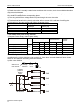
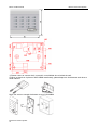
2.1 Units Dimension
8HP/10HP Dimensions (Combinable):
MCAC-VTSM-2012-09
MCAC-VTSM-2012-09
Specification and performance
Liquid side
(The connected pipe
diameter Φ12.7)
Gauge point
Detect the pressure/
Refrigerant replenishment
Oil balancer
For parallel connect
the modular units
Gas side
(The connected pipe
diameter Φ25.4)
Position of Foot screw bolt (Unit: mm)
B
C
D
A
15×23 long u-shape hole
For 8,10HP
For 12,14,16HP
A
700
1120
B
960
1250
C
736
736
D
765
765
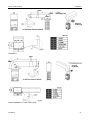
Specification and performance
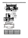
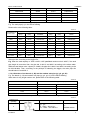
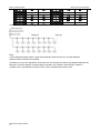
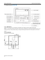
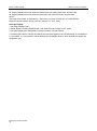
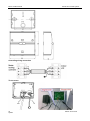
2.2 12HP/14HP/16HP (Combinable)Dimensions:
MCAC-VTSM-2012-09
MCAC-VTSM-2012-09
Specification and performance
Liquid side
(The connected pipe
diameter Φ15.9)
Gauge point
Detect the pressure/
Refrigerant replenishment
Oil balancer
For parallel connect
the modular units
Gas side
(The connected pipe
diameter Φ31.8)
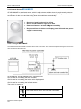
2.3 Valve explanation
1
4
2
3
5
Connect the liquid pipe (accessory, field installation)
Connect the gas pipe
Low pressure float valve
Oil balance pipe (only for combination)
Low pressure float valve
Specification and performance
MCAC-VTSM-2012-09
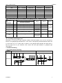
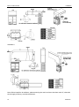
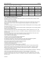
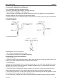
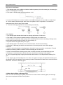
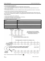
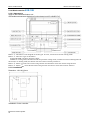
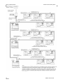
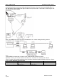
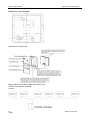
3. Piping Diagrams
DC Fan
SV6
Stop Valve
(High Pressure)
EXV A
Heat Exchanger
SV5
Stop Valve
(Low Pressure)
ST 1
unloading valve
High Pressure HPS
Switch
Oil Balance
Compressor
INVERTER
Oil Separator
High Pressure
Sensor SENP
SV 4
Low Pressure
Receiver
Low
Pressure
Switch
LPS
SV 2
8~10HP
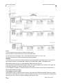
SV6
DC Fan
Stop Valve
(High Pressure)
EXV A
Heat Exchanger
SV5
Stop Valve
(Low Pressure)
ST 1
unloading valve
Oil Balance
Oil Separator
SENP
Compressor
FIX
Compressor
INVERTER
High Pressure HPS
High
Switch
Pressure
Sensor
SV4
Low
Pressure
Switch
LPS
Low Pressure
Receiver
SV2
12HP
SV6
DC Fan
Stop Valve
(High Pressure)
EXV A
EXV B
Heat Exchanger
SV5
Stop Valve
(Low Pressure)
ST 1
unloading valve
High Pressure HPS
High
Switch
Pressure
Sensor
Oil Separator
Compressor
FIX
Compressor
INVERTER
SENP
Oil Balance
SV4
Low Pressure
Receiver
Low
Pressure
Switch
LPS
SV2
14~16HP
Remark:
1, 8~10 HP models only have one inverter compressor.
2, 12HP has one big capacity inverter compressor and a small fix scroll compressor.
3, 14~16HP models have two EXV part at the high-pressure pipe side, different with 12HP model.
MCAC-VTSM-2012-09
Specification and performance
Key Components:
Oil Separator: used to separate oil from high pressure & temperature gas refrigerant, which is pumped
out from compressor. The separation efficiency is up to 99%, it makes the oil return back to each
compressor very soon.
Low pressure receiver: It is used to store the liquid refrigerant and oil, it can protect the compressor
from liquid hammer.
Four-way valve control (ST1): Closes in cooling mode and opens in heating mode
EXV (electromagnetic expansion valve) control:
1) Max. Open degree is 480 pulses.
2) Generally, when system is plug in the EXV closes 700pulse first, then opens to 350 pulse and stand
by. When then the unit started, it opens to the right pulse.
3) When the running outdoor unit receives OFF signal, the EXV of slave unit will stop, while master unit
is running and slave unit stopped at the same time. If all outdoor units stopped, the EXV will close first,
and then open to the pulse of stand-by.
4) 8HP~12HP models have one EXV; 14~16HP models have double EXVs
SV2: spray a little liquid refrigerant to cooling compressor. Open when any compressor discharge
temperature is higher than 100℃.
SV4: oil returning valve. Opens after the DC inverter compressor has been run for 5 minutes and then
closes 15 minutes later. (For the system has only one outdoor unit).
Every 20 minutes, SV4 of each outdoor unit opens for 3 minutes. (For the system has more than one
outdoor unit)
SV5: for defrosting. In defrosting mode, the opening of SV5 can cut the refrigerant flowing circle, so the
defrosting process will takes less time. In cooling mode, it is always off.
SV6: for by-pass. Closed when the unit stands by and system is running at heating mode. Open when
the discharge temperature is over-high in cooling mode, and close when the unit is standby or system is
in heating mode.
Hi pressure sensor: To supervisor the discharge pressure of the compressor and to control the DC fan
speed.
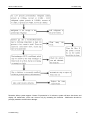
For example.
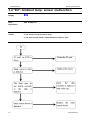
Cooling mode launch sequence (The unit has accomplish commissioning):
Plug in and unit start----------SV4, SV5 open
Inverter compressor start at 40hz
50s later
60s later
SV5 closed
60s later
SV4 closed
Inverter compressor start at 30hz 20s later
compressor start (This step is omitted for 8HP&10HP models)
frequency will adjust according the capacity requirement.
40s later
40s later
Fix scroll
Inverter compressor running
Specification and performance
MCAC-VTSM-2012-09
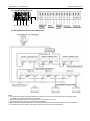
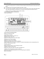
4. Electric Characteristics
Model
Outdoor Unit
Power Supply
Compressor
OFM
Hz
Voltage
Min.
Max.
MCA
TOCA
MFA
MSC
RLA
KW
FLA
MDV-252(8)W/DRN1(C)
50
380~415
342
440
21.8
24.5
25
-
17.4
0.424
4.4
MDV-280(10)W/DRN1(C)
50
380~415
342
440
21.8
24.5
25
-
17.4
0.424
4.4
MDV-335(12)W/ DRN1(C)
50
380~415
342
440
20
24.5
40
-/68
6.2/9.8
0.424
4.4
MDV-400(14)W/ DRN1(C)
50
380~415
342
440
32.8
33
40
-/62
17.4/8.8
0.42+0.38
4.2+2.9
MDV-450(16)W/ DRN1(C)
50
380~415
342
440
34
33
50
-/68
17.4/9.8
0.42+0.38
4.2+2.9
Remark:
MCA: Min. Current Amps. (A)
TOCA: Total Over-current Amps. (A)
MFA: Max. Fuse Amps. (A)
MSC: Max. Starting Amps. (A)
RLA: Rated Load Amps. (A)
OFM: Outdoor Fan Motor.
FLA: Full Load Amps. (A)
KW: Rated Motor Output (KW)
Notes:
1. RLA is based on the following conditions, Indoor temp. 27℃ DB/19℃ WB,Outdoor temp. 35℃ DB
2. TOCA means the total value of each OC set.
3. MSC means the Max. current during the starting of compressor.
4. Voltage range. Units are suitable for use on electrical systems where voltage supplied to unit terminals is not below or
above listed range limits.
5. Maximum allowable voltage variation between phases is 2%
6. Selection wire size based on the larger value of MCA or TOCA
7. MFA is used to select the circuit breaker and the ground fault circuit interrupter (earth circuit breaker).
MCAC-VTSM-2012-09
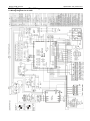
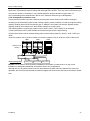
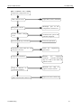
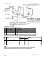
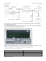
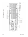
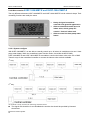
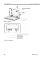
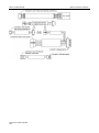
5. Wiring Diagrams and Field Wiring
5.1 Wiring Diagrams for 8~16HP
Specification and performance
Specification and performance
MCAC-VTSM-2012-09
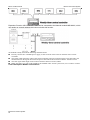
1.2 Field Wiring
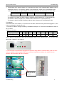
a) Terminal of Outdoor unit
A
B
C
N
To 380-415V 3N~ 50Hz
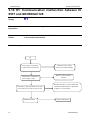
b) Wiring between Indoor and Outdoor unit
Note:
1. The signal connecting line between outdoor units, indoor and outdoor units and indoor units has polarity. When
connecting, be careful to prevent error connection.
2. Signal line shall adopt three-core shielded wire with an area above 0.75 mm2.
3. Do not bind signal line and copper pipe together with belting.
4. Make sure that the shield metal layer should be grounded well indoor control box in order to prevent interference.
5. It’s forbidden to connect 200V or above high-volt live wire to the communication terminal.
MCAC-VTSM-2012-09
Specification and performance
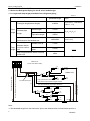
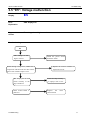
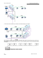
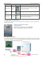
1.3 Outdoor unit power wiring
5.3.1 Separate Power Supply (without power facility)
Minimum Power wire diameter
(mm2)
Item
Power supply
Model
Ground
4*10mm2(L≤20m)
MDV-280(10)W/DRN1(C)
2
380V~415V, 3N, 4*16mm (L≤50m)
MDV-335(12)W/DRN1(C) 50Hz
4*16mm2 (L≤20m)
MDV-400(14)W/DRN1(C)
4*25mm2 (L≤50m)
35(L≤78m)
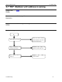
5.3.2 With power facilities:
Outdoor unit
power supply
380-415V 3N~ 50Hz
Leakage
protector
Manual
switch
Leakage
protector
Manual
switch
(a)
Outdoor unit
GND
Outdoor unit
GND
Outdoor unit
Branch box
Outdoor unit
Outdoor unit
Power facilities 1
(with leakage protector)
(a)
Outdoor unit
Leakage
protector
Manual
switch
Outdoor unit
(b)
Outdoor unit
Branch box
Outdoor unit
Power facilities 2
(with leakage protector)
wire
Capacity
Fuse
32
25
10
MDV-450(16)W/DRN1(C)
Leakage
protector
Wiring of mental and synthetic resin
Size
MDV-252(8)W/DRN1(C)
manual switch(A)
Outdoor unit
GND
GND
GND
GND
GND
GND
GND
GND
50
40
50
40
63
50
16
100 mA under
0.1sec
Specification and performance
MCAC-VTSM-2012-09
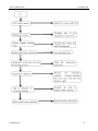
Note:
1, Select power cord for these five models separately according to relevant standard. 8HP, 10HP, 12HP, 14HP, 16HP.
2, The wiring diameter and the length in the table indicate the condition that the voltage dropping range is within 2%. If the
length exceeds the above figure, please select the wire diameter according to relevant standard.
3, Select the wire diameter
Power wiring refer to the main wire (a) connecting to branch box and the wiring (b) between branch box and power
facilities. Please select the wire diameter according to the following requirement.
4, Diameter of main wire (a)
Depend on the total horsepower of outdoor unit and following table.
E.g In system:(8Hp×1unit+8Hp×1unit+10Hp×1unit)
Total Hp=26Hp→(Table.6-4)→size of wire=35mm2(within 50m)
5, Wiring (b):between branch box and power equipment. Depends on the number of combined outdoor unit. If fewer than
5, the diameter is the same as that of main wire (a); if more than 6, there will be 2 electric control boxes, and the diameter
of wiring depends on the total horsepower of outdoor units connecting to each electric control box and following table.
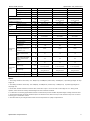
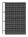
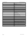
5.3.3 Reference table of the cable size for each capacity
Min. Diameter of wiring (mm2 )
Total capacity (HP)
from weather proof isolator to ODU
Below 20 m
20 to 50 m
8
10
16
10
10
16
12
10
16
14
16
25
16
16
25
18
16
25
20
25
35
22
25
35
24
25
35
26
25
35
28
25
35
30
35
50
32
35
50
34
35
50
36
35
50
38
35
50
40
35
50
42
50
70
44
50
70
46
50
70
48
50
70
50
70
95
52
70
95
54
70
95
MCAC-VTSM-2012-09
Specification and performance
56
90
110
58
90
110
60
90
110
62
90
110
64
90
110
Remark: The above selection is just for reference, it should be considered that the cable layout, space between cable
and surroundings, etc. for an actual electrical project
Specification and performance
MCAC-VTSM-2012-09
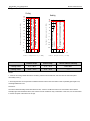
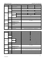
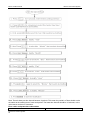
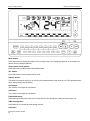
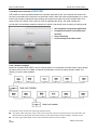
6. Operation Limits
Cooling
20
15
10
5
0
15
10
5
0
-5
-10
-15
-20
-5
-10
10
Range for continuous operation
25
20
Range for intermittent
operation
30
30
27
25
Outdoor temperature (℃ WB)
35
Range for intermittent operation
Outdoor temperature (℃ DB)
40
Heating
Range for continuous operation
50
48
45
1517 20
25
32
30 35
10
Indoor temperature (℃ WB)
15
20
25
30
35
Indoor temperature (℃ DB)
Outdoor temp.
Indoor temp.
Room relative humidity
Cooling mode
-5°C ~ 48°C
17°C ~ 32°C
below 80%
Heating mode
-20°C ~ 27°C
15°C ~ 30°C
───
Notes:
1. If the unit is running outside the above condition, protective device will start, and even then the units take place
abnormality running.
2. These figures base on the operation conditions between indoor units and outdoor units: Equivalent pipe length is 5m,
and height difference is 0m.
Precaution:
The indoor relative humidity should be lower than 80%. If the air conditioner works in an environment with a relative
humidity higher than mentioned above, the surface of the air conditioner may condensate. In this case, it is recommended
to set the air speed of the indoor unit to high.
MCAC-VTSM-2012-09
Specification and performance
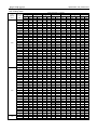
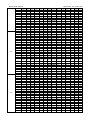
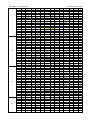
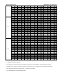
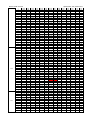
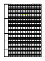
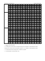
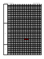
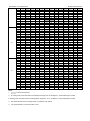
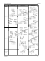
7. Capacity Tables
8HP cooling mode
Combinatio
n (%)
(Capacity
index)
130%
120%
110%
Outdoor
temperatu
re (°C
DB)
DB:20.8,WB:1
4
TC
PI
DB:23.3,WB:1
6
TC
PI
Indoor temperature(°C DB/WD)
DB:25.8,WB:1
DB:27,WB:19
DB:28.2,WB:20
8
TC
PI
TC
PI
TC
PI
DB:30.7,WB:2
2
TC
PI
DB:32,WB:24
TC
PI
kW
kW
kW
kW
kW
kW
kW
kW
kW
kW
kW
kW
kW
kW
-5
22.14
2.40
26.37
2.93
30.60
3.14
31.77
3.27
33.30
3.36
34.11
3.66
34.97
3.68
-2
22.14
2.40
26.37
2.99
30.60
3.14
31.77
3.29
33.30
3.36
34.11
3.70
34.97
3.72
0
22.14
2.44
26.37
3.04
30.60
3.26
31.77
3.47
33.30
3.56
34.11
3.75
34.97
3.77
2
22.14
2.49
26.37
3.05
30.60
3.37
31.77
3.66
33.30
3.60
34.11
3.78
34.97
3.82
4
22.14
2.54
26.37
3.11
30.60
3.48
31.77
3.68
33.30
3.65
34.11
3.77
34.97
3.89
6
22.14
2.59
26.37
3.17
30.60
3.61
31.77
3.71
32.93
3.76
33.69
3.77
34.58
3.92
8
22.14
2.65
26.37
3.24
30.60
3.79
31.77
3.89
32.52
3.88
33.33
3.90
34.14
3.96
10
22.14
2.71
26.37
3.31
30.60
3.93
31.77
4.02
32.13
4.04
32.94
4.06
33.75
4.08
12
22.14
2.76
26.37
3.37
30.60
4.01
31.32
4.03
31.77
4.06
32.49
4.07
33.30
4.10
14
22.14
2.81
26.37
3.44
30.51
4.05
30.96
4.06
31.32
4.08
32.13
4.09
32.94
4.19
16
22.14
2.86
26.37
3.51
30.15
4.06
30.51
4.08
30.87
4.10
31.68
4.12
32.49
4.26
18
22.14
2.91
26.37
3.58
29.70
4.20
30.06
4.22
30.51
4.24
31.32
4.28
32.13
4.32
20
22.14
2.98
26.37
3.81
29.25
4.40
29.70
4.43
30.06
4.45
30.87
4.49
31.68
4.54
21
22.14
3.06
26.37
3.94
29.07
4.51
29.52
4.53
29.88
4.55
30.69
4.60
31.50
4.64
23
22.14
3.28
26.37
4.23
28.71
4.71
29.07
4.73
29.43
4.76
30.24
4.81
31.05
4.85
25
22.14
3.50
26.37
4.53
28.26
4.92
28.62
4.94
29.07
4.97
29.88
5.02
30.69
5.07
27
22.14
3.74
26.37
4.85
27.90
5.12
28.26
5.15
28.62
5.18
29.43
5.23
30.24
5.29
29
22.14
3.99
26.37
5.18
27.45
5.33
27.81
5.36
28.26
5.39
29.07
5.45
29.88
5.50
31
22.14
4.26
26.28
5.48
27.00
5.54
27.45
5.57
27.81
5.60
28.62
5.66
29.43
5.72
33
22.14
4.54
25.83
5.68
26.64
5.75
27.00
5.78
27.45
5.81
28.26
5.87
28.98
5.94
35
22.14
4.84
25.38
5.89
26.19
5.96
26.64
5.99
27.00
6.03
27.81
6.10
28.62
6.16
37
22.14
5.15
25.02
6.10
25.83
6.18
26.19
6.21
26.64
6.25
27.36
6.32
28.17
6.39
39
22.14
5.48
24.57
6.17
25.38
6.38
25.83
6.42
26.19
6.46
27.00
6.53
27.81
6.61
41
22.14
5.77
24.32
6.23
25.11
6.44
25.56
6.48
25.92
6.52
26.73
6.54
26.74
6.67
43
22.14
5.91
24.14
6.26
24.98
6.46
25.43
6.51
25.66
6.53
26.25
6.56
26.42
6.69
45
22.14
6.21
23.99
6.32
24.71
6.52
25.16
6.55
25.28
6.56
25.53
6.58
25.91
6.81
48
-5
22.14
5.02
24.84
4.84
26.94
5.02
27.44
4.98
27.66
5.00
27.54
5.00
28.04
5.40
20.43
2.32
24.30
2.81
28.26
3.32
30.24
3.62
31.68
3.78
32.40
3.90
33.12
4.00
-2
20.43
2.34
24.30
2.84
28.26
3.35
30.24
3.64
31.68
3.82
32.40
3.93
33.12
4.01
0
20.43
2.36
24.30
2.86
28.26
3.39
30.24
3.65
31.68
3.85
32.40
3.95
33.12
4.02
2
20.43
2.37
24.30
2.89
28.26
3.42
30.24
3.69
31.68
3.87
32.40
3.98
33.12
4.03
4
20.43
2.39
24.30
2.92
28.26
3.46
30.24
3.72
31.68
3.92
32.40
3.99
33.12
4.04
6
20.43
2.42
24.30
2.95
28.26
3.51
30.24
3.76
31.68
3.96
32.40
4.02
33.12
4.05
8
20.43
2.44
24.30
2.98
28.26
3.55
30.24
3.81
31.68
4.00
32.40
4.04
33.12
4.07
10
20.43
2.47
24.30
3.02
28.26
3.59
30.24
3.88
31.68
4.01
32.40
4.05
33.12
4.09
12
20.43
2.52
24.30
3.07
28.26
3.66
30.24
3.95
31.23
4.02
31.95
4.03
32.67
4.12
14
20.43
2.57
24.30
3.14
28.26
3.73
30.24
4.03
30.78
4.05
31.59
4.09
32.31
4.17
16
20.43
2.61
24.30
3.20
28.26
3.80
30.06
4.10
30.42
4.11
31.14
4.16
31.86
4.23
18
20.43
2.66
24.30
3.26
28.26
3.93
29.61
4.20
29.97
4.21
30.69
4.25
31.50
4.29
20
20.43
2.72
24.30
3.39
28.26
4.23
29.25
4.40
29.61
4.42
30.33
4.46
31.05
4.50
21
20.43
2.74
24.30
3.51
28.26
4.38
28.98
4.50
29.34
4.52
30.15
4.56
30.87
4.61
23
20.43
2.93
24.30
3.76
28.26
4.69
28.62
4.70
28.98
4.73
29.70
4.77
30.42
4.81
25
20.43
3.13
24.30
4.02
27.81
4.89
28.17
4.91
28.53
4.93
29.34
4.98
30.06
5.03
27
20.43
3.34
24.30
4.30
27.45
5.09
27.81
5.12
28.17
5.15
28.89
5.19
29.61
5.24
29
20.43
3.56
24.30
4.59
27.00
5.30
27.36
5.33
27.72
5.35
28.44
5.41
29.25
5.45
31
20.43
3.80
24.30
4.90
26.55
5.51
27.00
5.53
27.36
5.57
28.08
5.62
28.80
5.68
33
20.43
4.05
24.30
5.23
26.19
5.72
26.55
5.75
26.91
5.77
27.63
5.83
28.35
5.89
35
20.43
4.31
24.30
5.57
25.74
5.92
26.10
5.95
26.55
5.98
27.27
6.05
27.99
6.11
37
20.43
4.58
24.30
5.94
25.38
6.14
25.74
6.17
26.10
6.20
26.82
6.26
27.54
6.33
39
20.43
4.88
24.21
6.27
24.93
6.34
25.29
6.38
25.65
6.41
26.46
6.48
27.18
6.55
41
20.43
5.01
24.01
6.31
24.73
6.39
25.09
6.43
25.45
6.46
26.26
6.50
26.40
6.60
43
20.43
5.08
23.89
6.36
24.54
6.42
24.90
6.45
25.26
6.48
25.81
6.52
25.99
6.73
45
20.43
5.14
23.76
6.42
24.30
6.48
24.64
6.51
25.04
6.53
25.29
6.54
25.73
6.87
48
-5
23.67
3.35
27.29
4.17
27.80
4.22
28.09
4.27
28.69
4.26
28.84
4.20
29.42
4.46
18.72
2.02
22.32
2.52
25.92
3.01
27.72
3.23
29.52
3.47
31.77
3.61
32.49
3.72
-2
18.72
2.06
22.32
2.55
25.92
3.03
27.72
3.26
29.52
3.50
31.77
3.64
32.49
3.74
0
18.72
2.08
22.32
2.57
25.92
3.06
27.72
3.28
29.52
3.54
31.77
3.68
32.49
3.78
Specification and performance
100%
90%
MCAC-VTSM-2012-09
2
18.72
2.13
22.32
2.59
25.92
3.10
27.72
3.32
29.52
3.58
31.77
3.73
32.49
3.83
4
18.72
2.17
22.32
2.62
25.92
3.13
27.72
3.36
29.52
3.63
31.77
3.78
32.49
3.87
6
18.72
2.19
22.32
2.65
25.92
3.16
27.72
3.41
29.52
3.67
31.77
3.82
32.49
3.93
8
18.72
2.21
22.32
2.69
25.92
3.20
27.72
3.45
29.52
3.72
31.77
3.85
32.49
3.97
10
18.72
2.24
22.32
2.73
25.92
3.25
27.72
3.51
29.52
3.78
31.77
3.88
32.49
4.00
12
18.72
2.29
22.32
2.79
25.92
3.31
27.72
3.58
29.52
3.85
31.41
3.93
32.04
4.05
14
18.72
2.33
22.32
2.83
25.92
3.37
27.72
3.64
29.52
3.92
30.96
3.97
31.68
4.08
16
18.72
2.37
22.32
2.89
25.92
3.44
27.72
3.71
29.52
4.00
30.60
4.01
31.23
4.13
18
18.72
2.41
22.32
2.95
25.92
3.51
27.72
3.82
29.52
4.19
30.15
4.22
30.87
4.26
20
18.72
2.46
22.32
3.01
25.92
3.71
27.72
4.10
29.07
4.39
29.79
4.43
30.42
4.47
21
18.72
2.49
22.32
3.10
25.92
3.85
27.72
4.25
28.89
4.50
29.52
4.53
30.24
4.57
23
18.72
2.60
22.32
3.32
25.92
4.12
27.72
4.56
28.44
4.69
29.16
4.74
29.79
4.78
25
18.72
2.78
22.32
3.55
25.92
4.41
27.72
4.88
28.08
4.90
28.71
4.95
29.43
4.99
27
18.72
2.96
22.32
3.79
25.92
4.72
27.27
5.09
27.63
5.11
28.35
5.15
28.98
5.20
29
18.72
3.16
22.32
4.05
25.92
5.04
26.91
5.30
27.27
5.32
27.90
5.37
28.62
5.42
31
18.72
3.36
22.32
4.31
25.92
5.38
26.46
5.50
26.82
5.53
27.54
5.57
28.17
5.63
33
18.72
3.58
22.32
4.60
25.74
5.68
26.10
5.71
26.46
5.73
27.09
5.79
27.81
5.84
35
18.72
3.81
22.32
4.90
25.29
5.88
25.65
5.91
26.01
5.95
26.64
6.00
27.36
6.06
37
18.72
4.05
22.32
5.22
24.93
6.10
25.29
6.12
25.56
6.15
26.28
6.21
26.91
6.27
39
18.72
4.31
22.32
5.56
24.48
6.30
24.84
6.33
25.20
6.37
25.83
6.43
26.55
6.49
41
18.72
4.35
22.32
5.60
24.29
6.35
24.65
6.38
25.01
6.41
25.50
6.47
25.75
6.54
43
18.72
4.40
22.32
5.67
24.10
6.39
24.46
6.42
24.82
6.45
25.28
6.50
25.36
6.67
45
18.72
4.54
22.32
5.71
23.85
6.45
24.20
6.50
24.60
6.51
25.02
6.67
25.12
6.82
48
-5
20.50
3.35
24.45
4.18
25.74
4.72
26.08
4.79
26.63
4.76
26.95
5.18
27.16
5.00
17.01
1.84
20.25
2.22
23.58
2.64
25.20
2.83
26.82
3.07
30.15
3.50
31.86
3.65
-2
17.01
1.87
20.25
2.25
23.58
2.67
25.20
2.88
26.82
3.11
30.15
3.54
31.86
3.68
0
17.01
1.89
20.25
2.27
23.58
2.70
25.20
2.92
26.82
3.14
30.15
3.60
31.86
3.72
2
17.01
1.92
20.25
2.30
23.58
2.73
25.20
2.96
26.82
3.18
30.15
3.65
31.86
3.78
4
17.01
1.94
20.25
2.33
23.58
2.77
25.20
3.00
26.82
3.22
30.15
3.69
31.86
3.82
6
17.01
1.96
20.25
2.37
23.58
2.81
25.20
3.05
26.82
3.27
30.15
3.74
31.86
3.88
8
17.01
2.00
20.25
2.41
23.58
2.86
25.20
3.09
26.82
3.32
30.15
3.80
31.86
3.94
10
17.01
2.03
20.25
2.45
23.58
2.91
25.20
3.14
26.82
3.38
30.15
3.86
31.86
4.00
12
17.01
2.06
20.25
2.50
23.58
2.96
25.20
3.20
26.82
3.44
30.15
3.93
31.41
4.03
14
17.01
2.10
20.25
2.55
23.58
3.02
25.20
3.26
26.82
3.51
30.15
4.01
31.05
4.08
16
17.01
2.14
20.25
2.60
23.58
3.08
25.20
3.32
26.82
3.58
29.97
4.06
30.60
4.12
18
17.01
2.18
20.25
2.64
23.58
3.13
25.20
3.39
26.82
3.65
29.61
4.20
30.24
4.23
20
17.01
2.22
20.25
2.70
23.58
3.23
25.20
3.56
26.82
3.91
29.16
4.39
29.79
4.43
21
17.01
2.24
20.25
2.72
23.58
3.35
25.20
3.69
26.82
4.05
28.98
4.50
29.61
4.54
23
17.01
2.30
20.25
2.91
23.58
3.59
25.20
3.95
26.82
4.34
28.62
4.70
29.16
4.74
25
17.01
2.45
20.25
3.10
23.58
3.84
25.20
4.24
26.82
4.65
28.17
4.91
28.80
4.95
27
17.01
2.61
20.25
3.31
23.58
4.10
25.20
4.53
26.82
4.97
27.72
5.11
28.35
5.16
29
17.01
2.78
20.25
3.53
23.58
4.38
25.20
4.84
26.73
5.28
27.36
5.33
27.99
5.37
31
17.01
2.96
20.25
3.77
23.58
4.67
25.20
5.16
26.37
5.49
26.91
5.53
27.54
5.58
33
17.01
3.14
20.25
4.01
23.58
4.98
25.20
5.51
25.92
5.69
26.55
5.74
27.18
5.79
35
17.01
3.34
20.25
4.27
23.58
5.31
25.20
5.87
25.47
5.90
26.10
5.95
26.73
6.00
37
17.01
3.55
20.25
4.54
23.58
5.66
24.75
6.08
25.11
6.11
25.74
6.17
26.28
6.21
39
17.01
3.78
20.25
4.83
23.58
6.02
24.39
6.29
24.66
6.32
25.29
6.37
25.92
6.44
41
17.01
3.95
20.25
5.01
23.58
6.24
24.01
6.33
24.47
6.41
24.85
6.52
25.54
6.57
43
17.01
4.13
20.25
5.18
23.58
6.36
23.63
6.40
24.29
6.48
25.00
6.57
25.09
6.64
45
17.01
4.36
20.25
5.42
23.58
6.47
23.13
6.49
24.17
6.59
24.79
6.67
24.59
6.73
48
-5
17.62
4.58
20.97
5.61
24.42
6.48
22.97
6.39
24.99
6.66
24.11
6.65
24.91
6.71
15.30
1.63
18.27
1.96
21.24
2.31
22.68
2.52
24.12
2.68
27.09
3.08
30.06
3.53
-2
15.30
1.65
18.27
1.98
21.24
2.34
22.68
2.55
24.12
2.71
27.09
3.11
30.06
3.56
0
15.30
1.67
18.27
2.00
21.24
2.37
22.68
2.58
24.12
2.75
27.09
3.15
30.06
3.59
2
15.30
1.70
18.27
2.03
21.24
2.40
22.68
2.62
24.12
2.79
27.09
3.21
30.06
3.64
4
15.30
1.72
18.27
2.06
21.24
2.44
22.68
2.66
24.12
2.83
27.09
3.26
30.06
3.70
6
15.30
1.75
18.27
2.10
21.24
2.48
22.68
2.71
24.12
2.88
27.09
3.31
30.06
3.76
8
15.30
1.78
18.27
2.14
21.24
2.53
22.68
2.75
24.12
2.93
27.09
3.37
30.06
3.79
10
15.30
1.81
18.27
2.18
21.24
2.58
22.68
2.79
24.12
2.99
27.09
3.42
30.06
3.85
12
15.30
1.84
18.27
2.22
21.24
2.63
22.68
2.83
24.12
3.05
27.09
3.48
30.06
3.93
14
15.30
1.88
18.27
2.26
21.24
2.68
22.68
2.89
24.12
3.10
27.09
3.55
30.06
4.00
16
15.30
1.91
18.27
2.30
21.24
2.73
22.68
2.94
24.12
3.17
27.09
3.62
29.97
4.07
18
15.30
1.94
18.27
2.35
21.24
2.78
22.68
3.00
24.12
3.23
27.09
3.69
29.61
4.20
20
15.30
1.98
18.27
2.40
21.24
2.83
22.68
3.06
24.12
3.35
27.09
3.97
29.16
4.39
MCAC-VTSM-2012-09
80%
70%
Specification and performance
21
15.30
1.99
18.27
2.42
21.24
2.88
22.68
3.17
24.12
3.47
27.09
4.11
28.98
4.50
23
15.30
2.03
18.27
2.52
21.24
3.09
22.68
3.40
24.12
3.72
27.09
4.41
28.53
4.70
25
15.30
2.15
18.27
2.69
21.24
3.30
22.68
3.63
24.12
3.97
27.09
4.72
28.17
4.91
27
15.30
2.28
18.27
2.87
21.24
3.52
22.68
3.88
24.12
4.25
27.09
5.05
27.72
5.11
29
15.30
2.43
18.27
3.06
21.24
3.76
22.68
4.14
24.12
4.54
26.82
5.28
27.36
5.32
31
15.30
2.58
18.27
3.25
21.24
4.01
22.68
4.42
24.12
4.84
26.37
5.49
26.91
5.53
33
15.30
2.74
18.27
3.46
21.24
4.27
22.68
4.71
24.12
5.17
26.01
5.70
26.55
5.74
35
15.30
2.91
18.27
3.68
21.24
4.55
22.68
5.02
24.12
5.51
25.56
5.91
26.10
5.95
37
15.30
3.09
18.27
3.91
21.24
4.84
22.68
5.34
24.12
5.87
25.11
6.11
25.74
6.16
39
15.30
3.28
18.27
4.16
21.24
5.15
22.68
5.69
24.12
6.25
24.75
6.33
25.29
6.37
41
15.30
3.39
18.27
4.35
21.24
5.34
22.68
5.84
24.12
6.29
24.58
6.49
25.12
6.52
43
15.30
3.55
18.27
4.54
21.24
5.53
22.68
5.99
24.12
6.43
24.45
6.57
24.90
6.62
45
15.30
3.78
18.27
4.77
21.24
5.76
22.68
6.19
24.12
6.60
24.32
6.64
24.52
6.71
48
-5
15.30
2.90
18.27
3.60
21.24
4.30
22.68
4.61
24.12
4.81
26.79
4.79
26.51
4.84
13.59
1.44
16.20
1.70
18.81
2.01
20.16
2.14
21.51
2.30
24.12
2.66
26.73
3.04
-2
13.59
1.46
16.20
1.72
18.81
2.03
20.16
2.17
21.51
2.33
24.12
2.69
26.73
3.07
0
13.59
1.48
16.20
1.74
18.81
2.05
20.16
2.20
21.51
2.37
24.12
2.73
26.73
3.11
2
13.59
1.51
16.20
1.77
18.81
2.08
20.16
2.24
21.51
2.41
24.12
2.78
26.73
3.17
4
13.59
1.54
16.20
1.80
18.81
2.12
20.16
2.29
21.51
2.45
24.12
2.83
26.73
3.21
6
13.59
1.56
16.20
1.84
18.81
2.16
20.16
2.34
21.51
2.50
24.12
2.87
26.73
3.27
8
13.59
1.59
16.20
1.88
18.81
2.21
20.16
2.38
21.51
2.55
24.12
2.92
26.73
3.33
10
13.59
1.61
16.20
1.92
18.81
2.26
20.16
2.44
21.51
2.61
24.12
2.98
26.73
3.36
12
13.59
1.63
16.20
1.96
18.81
2.30
20.16
2.49
21.51
2.67
24.12
3.04
26.73
3.43
14
13.59
1.66
16.20
1.99
18.81
2.34
20.16
2.53
21.51
2.72
24.12
3.10
26.73
3.49
16
13.59
1.69
16.20
2.03
18.81
2.39
20.16
2.57
21.51
2.76
24.12
3.16
26.73
3.55
18
13.59
1.72
16.20
2.07
18.81
2.44
20.16
2.63
21.51
2.82
24.12
3.22
26.73
3.63
20
13.59
1.75
16.20
2.11
18.81
2.49
20.16
2.68
21.51
2.87
24.12
3.34
26.73
3.88
21
13.59
1.77
16.20
2.12
18.81
2.51
20.16
2.71
21.51
2.94
24.12
3.46
26.73
4.02
23
13.59
1.80
16.20
2.17
18.81
2.63
20.16
2.88
21.51
3.14
24.12
3.70
26.73
4.31
25
13.59
1.85
16.20
2.30
18.81
2.81
20.16
3.08
21.51
3.36
24.12
3.97
26.73
4.62
27
13.59
1.97
16.20
2.45
18.81
2.99
20.16
3.29
21.51
3.59
24.12
4.24
26.73
4.94
29
13.59
2.10
16.20
2.61
18.81
3.19
20.16
3.50
21.51
3.83
24.12
4.52
26.73
5.28
31
13.59
2.22
16.20
2.78
18.81
3.40
20.16
3.73
21.51
4.09
24.12
4.83
26.28
5.49
33
13.59
2.37
16.20
2.95
18.81
3.62
20.16
3.97
21.51
4.35
24.12
5.15
25.92
5.69
35
13.59
2.51
16.20
3.14
18.81
3.85
20.16
4.23
21.51
4.63
24.12
5.49
25.47
5.90
37
13.59
2.66
16.20
3.33
18.81
4.09
20.16
4.50
21.51
4.93
24.12
5.85
25.11
6.10
39
13.59
2.82
16.20
3.55
18.81
4.35
20.16
4.79
21.51
5.25
24.12
6.23
24.66
6.32
41
13.59
2.88
16.20
3.59
18.81
4.42
20.16
4.92
21.51
5.34
24.12
6.39
24.51
6.43
43
13.59
2.97
16.20
3.62
18.81
4.48
20.16
5.00
21.51
5.42
24.12
6.46
24.36
6.50
45
13.59
3.05
16.20
3.66
18.81
4.57
20.16
5.11
21.51
5.51
24.12
6.53
24.05
6.60
48
-5
13.59
2.00
16.20
2.39
21.16
3.01
20.16
3.40
21.51
3.63
24.12
4.28
26.83
4.38
11.88
1.28
14.22
1.50
16.47
1.70
17.64
1.83
18.81
1.95
21.06
2.23
23.40
2.57
-2
11.88
1.29
14.22
1.51
16.47
1.72
17.64
1.86
18.81
1.99
21.06
2.27
23.40
2.60
0
11.88
1.30
14.22
1.53
16.47
1.75
17.64
1.90
18.81
2.02
21.06
2.31
23.40
2.64
2
11.88
1.31
14.22
1.54
16.47
1.78
17.64
1.93
18.81
2.06
21.06
2.36
23.40
2.68
4
11.88
1.33
14.22
1.58
16.47
1.82
17.64
1.97
18.81
2.10
21.06
2.40
23.40
2.74
6
11.88
1.35
14.22
1.61
16.47
1.86
17.64
2.03
18.81
2.15
21.06
2.44
23.40
2.79
8
11.88
1.37
14.22
1.65
16.47
1.91
17.64
2.06
18.81
2.20
21.06
2.51
23.40
2.85
10
11.88
1.40
14.22
1.68
16.47
1.96
17.64
2.11
18.81
2.26
21.06
2.56
23.40
2.88
12
11.88
1.43
14.22
1.70
16.47
2.00
17.64
2.15
18.81
2.30
21.06
2.61
23.40
2.94
14
11.88
1.46
14.22
1.73
16.47
2.03
17.64
2.18
18.81
2.34
21.06
2.66
23.40
2.99
16
11.88
1.48
14.22
1.77
16.47
2.07
17.64
2.22
18.81
2.38
21.06
2.71
23.40
3.05
18
11.88
1.50
14.22
1.80
16.47
2.11
17.64
2.26
18.81
2.42
21.06
2.76
23.40
3.11
20
11.88
1.53
14.22
1.83
16.47
2.15
17.64
2.30
18.81
2.47
21.06
2.82
23.40
3.20
21
11.88
1.54
14.22
1.84
16.47
2.16
17.64
2.33
18.81
2.49
21.06
2.86
23.40
3.31
23
11.88
1.57
14.22
1.88
16.47
2.21
17.64
2.41
18.81
2.62
21.06
3.06
23.40
3.55
25
11.88
1.60
14.22
1.96
16.47
2.35
17.64
2.57
18.81
2.79
21.06
3.28
23.40
3.79
27
11.88
1.69
14.22
2.08
16.47
2.51
17.64
2.74
18.81
2.98
21.06
3.50
23.40
4.05
29
11.88
1.80
14.22
2.21
16.47
2.67
17.64
2.92
18.81
3.17
21.06
3.73
23.40
4.33
31
11.88
1.90
14.22
2.34
16.47
2.84
17.64
3.10
18.81
3.38
21.06
3.97
23.40
4.62
33
11.88
2.02
14.22
2.49
16.47
3.02
17.64
3.30
18.81
3.60
21.06
4.24
23.40
4.92
35
11.88
2.14
14.22
2.64
16.47
3.21
17.64
3.52
18.81
3.83
21.06
4.51
23.40
5.25
37
11.88
2.26
14.22
2.80
16.47
3.41
17.64
3.73
18.81
4.08
21.06
4.81
23.40
5.59
39
11.88
2.39
14.22
2.97
16.47
3.62
17.64
3.97
18.81
4.33
21.06
5.11
23.40
5.95
Specification and performance
60%
50%
MCAC-VTSM-2012-09
41
11.88
2.50
14.22
3.07
16.47
3.72
17.64
4.10
18.81
4.46
21.06
5.32
23.40
6.22
43
11.88
2.70
14.22
3.29
16.47
3.88
17.64
4.32
18.81
4.59
21.06
5.51
23.40
6.41
45
11.88
2.76
14.22
3.36
16.47
3.96
17.64
4.39
18.81
4.82
21.06
5.81
23.40
6.66
48
-5
11.88
5.18
14.22
6.28
16.47
7.41
17.64
8.10
18.81
8.75
21.06
10.55
23.40
11.98
10.17
1.09
12.15
1.27
14.13
1.48
15.12
1.58
16.11
1.70
18.09
1.91
20.07
2.19
-2
10.17
1.10
12.15
1.29
14.13
1.51
15.12
1.60
16.11
1.72
18.09
1.94
20.07
2.21
0
10.17
1.12
12.15
1.31
14.13
1.53
15.12
1.62
16.11
1.75
18.09
1.97
20.07
2.23
2
10.17
1.14
12.15
1.34
14.13
1.55
15.12
1.65
16.11
1.77
18.09
2.01
20.07
2.26
4
10.17
1.17
12.15
1.36
14.13
1.58
15.12
1.67
16.11
1.80
18.09
2.04
20.07
2.30
6
10.17
1.18
12.15
1.39
14.13
1.61
15.12
1.71
16.11
1.83
18.09
2.08
20.07
2.35
8
10.17
1.20
12.15
1.41
14.13
1.64
15.12
1.74
16.11
1.87
18.09
2.12
20.07
2.39
10
10.17
1.23
12.15
1.44
14.13
1.67
15.12
1.79
16.11
1.91
18.09
2.16
20.07
2.42
12
10.17
1.25
12.15
1.46
14.13
1.70
15.12
1.82
16.11
1.94
18.09
2.20
20.07
2.46
14
10.17
1.27
12.15
1.49
14.13
1.73
15.12
1.85
16.11
1.98
18.09
2.24
20.07
2.51
16
10.17
1.28
12.15
1.51
14.13
1.76
15.12
1.88
16.11
2.01
18.09
2.28
20.07
2.56
18
10.17
1.31
12.15
1.54
14.13
1.79
15.12
1.92
16.11
2.05
18.09
2.32
20.07
2.60
20
10.17
1.32
12.15
1.57
14.13
1.82
15.12
1.96
16.11
2.09
18.09
2.37
20.07
2.66
21
10.17
1.34
12.15
1.58
14.13
1.84
15.12
1.97
16.11
2.11
18.09
2.39
20.07
2.68
23
10.17
1.35
12.15
1.61
14.13
1.87
15.12
2.01
16.11
2.14
18.09
2.49
20.07
2.86
25
10.17
1.38
12.15
1.63
14.13
1.94
15.12
2.11
16.11
2.28
18.09
2.65
20.07
3.05
27
10.17
1.43
12.15
1.73
14.13
2.07
15.12
2.25
16.11
2.43
18.09
2.83
20.07
3.25
29
10.17
1.51
12.15
1.84
14.13
2.20
15.12
2.39
16.11
2.59
18.09
3.02
20.07
3.47
31
10.17
1.61
12.15
1.95
14.13
2.33
15.12
2.54
16.11
2.75
18.09
3.21
20.07
3.70
33
10.17
1.69
12.15
2.07
14.13
2.48
15.12
2.70
16.11
2.93
18.09
3.41
20.07
3.94
35
10.17
1.80
12.15
2.19
14.13
2.63
15.12
2.87
16.11
3.11
18.09
3.63
20.07
4.20
37
10.17
1.90
12.15
2.32
14.13
2.79
15.12
3.04
16.11
3.30
18.09
3.86
20.07
4.46
39
10.17
2.00
12.15
2.45
14.13
2.95
15.12
3.22
16.11
3.51
18.09
4.10
20.07
4.75
41
10.17
2.07
12.15
2.56
14.13
3.06
15.12
3.35
16.11
3.64
18.09
4.29
20.07
4.96
43
10.17
2.13
12.15
2.67
14.13
3.17
15.12
3.45
16.11
3.76
18.09
4.48
20.07
5.18
45
10.17
2.23
12.15
2.80
14.13
3.30
15.12
3.58
16.11
3.95
18.09
4.68
20.07
5.47
48
-5
10.17
3.13
12.15
3.89
14.13
4.51
15.12
4.94
16.11
5.54
18.09
6.41
20.07
7.67
8.51
0.95
10.17
1.10
11.79
1.26
12.60
1.32
13.41
1.40
15.03
1.59
16.74
1.71
-2
8.51
0.96
10.17
1.12
11.79
1.28
12.60
1.34
13.41
1.42
15.03
1.61
16.74
1.73
0
8.51
0.97
10.17
1.14
11.79
1.30
12.60
1.36
13.41
1.44
15.03
1.63
16.74
1.76
2
8.51
0.99
10.17
1.15
11.79
1.32
12.60
1.38
13.41
1.46
15.03
1.64
16.74
1.80
4
8.51
1.00
10.17
1.17
11.79
1.34
12.60
1.40
13.41
1.49
15.03
1.68
16.74
1.84
6
8.51
1.02
10.17
1.19
11.79
1.36
12.60
1.43
13.41
1.52
15.03
1.71
16.74
1.90
8
8.51
1.04
10.17
1.21
11.79
1.38
12.60
1.46
13.41
1.54
15.03
1.74
16.74
1.96
10
8.51
1.06
10.17
1.23
11.79
1.40
12.60
1.48
13.41
1.58
15.03
1.78
16.74
1.99
12
8.51
1.07
10.17
1.24
11.79
1.42
12.60
1.51
13.41
1.61
15.03
1.81
16.74
2.02
14
8.51
1.08
10.17
1.26
11.79
1.44
12.60
1.54
13.41
1.64
15.03
1.84
16.74
2.06
16
8.51
1.10
10.17
1.27
11.79
1.46
12.60
1.57
13.41
1.66
15.03
1.88
16.74
2.09
18
8.51
1.12
10.17
1.30
11.79
1.49
12.60
1.59
13.41
1.69
15.03
1.91
16.74
2.13
20
8.51
1.13
10.17
1.31
11.79
1.51
12.60
1.61
13.41
1.73
15.03
1.94
16.74
2.17
21
8.51
1.14
10.17
1.33
11.79
1.53
12.60
1.63
13.41
1.74
15.03
1.96
16.74
2.19
23
8.51
1.16
10.17
1.35
11.79
1.55
12.60
1.66
13.41
1.77
15.03
1.99
16.74
2.24
25
8.51
1.17
10.17
1.37
11.79
1.58
12.60
1.69
13.41
1.83
15.03
2.10
16.74
2.39
27
8.51
1.20
10.17
1.42
11.79
1.67
12.60
1.80
13.41
1.94
15.03
2.23
16.74
2.55
29
8.51
1.26
10.17
1.50
11.79
1.77
12.60
1.92
13.41
2.07
15.03
2.37
16.74
2.72
31
8.51
1.33
10.17
1.59
11.79
1.88
12.60
2.03
13.41
2.19
15.03
2.52
16.74
2.89
33
8.51
1.41
10.17
1.69
11.79
1.99
12.60
2.15
13.41
2.33
15.03
2.68
16.74
3.07
35
8.51
1.49
10.17
1.78
11.79
2.11
12.60
2.28
13.41
2.46
15.03
2.85
16.74
3.26
37
8.51
1.57
10.17
1.88
11.79
2.23
12.60
2.41
13.41
2.61
15.03
3.02
16.74
3.47
39
8.51
1.65
10.17
1.99
11.79
2.36
12.60
2.56
13.41
2.77
15.03
3.21
16.74
3.68
41
8.51
1.72
10.17
2.07
11.79
2.44
12.60
2.68
13.41
2.89
15.03
3.38
16.74
3.85
43
8.51
1.84
10.17
2.21
11.79
2.53
12.60
2.80
13.41
2.96
15.03
3.55
16.74
4.02
45
8.51
1.88
10.17
2.27
11.79
2.70
12.60
3.01
13.41
3.09
15.03
3.89
16.74
4.36
48
8.51
1.99
10.17
2.43
11.79
2.80
12.60
3.13
13.41
3.16
15.03
4.09
16.74
4.56
MCAC-VTSM-2012-09
Specification and performance
8HP heating mode
Indoor temperature(°C DB)
Combination
(Capacity
index)
130%
120%
110%
100%
Outdoor air
temp.
16
18
20
21
22
24
TC
PI
TC
PI
TC
PI
TC
PI
TC
PI
TC
PI
°C DB
-19.8
°C WB
-20
kW
17.48
kW
4.34
kW
17.40
kW
4.65
kW
17.32
kW
4.96
kW
17.32
kW
5.11
kW
17.23
kW
5.26
kW
17.23
kW
5.57
-18.8
-19
17.74
4.44
17.66
4.74
17.66
5.05
17.57
5.20
17.57
5.34
17.48
5.65
-16.7
-17
18.43
4.65
18.34
4.94
18.26
5.23
18.26
5.37
18.26
5.52
18.17
5.81
-13.7
-15
19.20
4.86
19.12
5.14
19.03
5.42
19.03
5.56
18.94
5.70
18.94
5.98
-11.8
-13
19.97
5.08
19.97
5.35
19.89
5.61
19.80
5.75
19.80
5.89
19.71
6.15
-9.8
-11
20.92
5.30
20.83
5.56
20.74
5.81
20.74
5.94
20.74
6.07
20.66
6.33
-9.5
-10
21.43
5.42
21.34
5.66
21.26
5.91
21.26
6.04
21.17
6.16
21.17
6.41
-8.5
-9.1
21.86
5.51
21.77
5.75
21.77
6.00
21.69
6.12
21.69
6.24
21.60
6.49
-7
-7.6
22.63
5.67
22.63
5.91
22.54
6.14
22.54
6.26
22.46
6.37
22.37
6.61
-5
-5.6
23.83
5.89
23.74
6.11
23.66
6.33
23.66
6.45
23.57
6.55
23.57
6.77
-3
-3.7
24.94
6.08
24.86
6.29
24.86
6.50
24.77
6.61
24.77
6.72
24.68
6.92
0
-0.7
26.91
6.37
26.91
6.57
26.83
6.76
26.83
6.84
26.74
6.96
26.74
7.16
3
2.2
29.05
6.64
28.97
6.82
28.89
7.00
28.89
7.09
28.89
7.19
28.80
7.36
5
4.1
30.51
6.80
30.43
6.98
30.43
7.15
30.34
7.24
30.34
7.32
30.26
7.49
7
6
32.06
6.97
31.97
7.12
31.97
7.29
31.88
7.37
31.88
7.45
30.60
7.16
9
7.9
33.68
7.11
33.60
7.27
33.60
7.42
33.51
7.50
32.83
7.34
30.60
6.72
11
9.8
35.40
7.25
35.31
7.40
35.14
7.49
33.94
7.20
32.83
6.90
30.60
6.33
13
11.8
37.28
7.39
37.20
7.53
35.14
7.02
33.94
6.74
32.83
6.48
30.60
5.94
15
13.7
39.08
7.52
37.37
7.13
35.14
6.61
33.94
6.36
32.83
6.10
30.60
5.61
-19.8
-20
17.40
4.76
17.31
5.04
17.23
5.33
17.23
5.46
17.23
5.61
17.14
5.89
-18.8
-19
17.66
4.85
17.57
5.13
17.57
5.41
17.49
5.54
17.49
5.69
17.40
5.97
-16.7
-17
18.34
5.04
18.26
5.31
18.14
5.57
18.17
5.71
18.17
5.85
18.09
6.11
-13.7
-15
19.12
5.24
19.03
5.50
18.94
5.75
18.94
5.89
18.94
6.01
18.86
6.27
-11.8
-13
19.89
5.44
19.89
5.69
19.80
5.93
19.80
6.06
19.72
6.18
19.72
6.43
-9.8
-11
20.83
5.65
20.74
5.88
20.74
6.12
20.66
6.24
20.66
6.35
20.57
6.59
-9.5
-10
21.35
5.75
21.26
5.98
21.17
6.21
21.17
6.33
21.17
6.44
21.09
6.67
-8.5
-9.1
21.77
5.84
21.69
6.06
21.69
6.29
21.60
6.40
21.60
6.52
21.51
6.74
-7
-7.6
22.54
5.99
22.54
6.21
22.46
6.42
22.46
6.53
22.37
6.64
22.37
6.85
-5
-5.6
23.74
6.18
23.66
6.39
23.57
6.60
23.57
6.70
23.57
6.81
23.49
7.00
-3
-3.7
24.86
6.37
24.86
6.57
24.77
6.76
24.77
6.85
24.69
6.96
24.69
7.15
0
-0.7
26.83
6.64
26.83
6.82
26.74
7.00
26.74
7.09
26.66
7.18
26.66
7.36
3
2.2
28.97
6.89
28.89
7.05
28.89
7.22
28.80
7.31
28.80
7.39
28.20
7.35
5
4.1
30.43
7.04
30.34
7.20
30.34
7.36
30.26
7.44
30.26
7.52
28.20
6.90
7
6
31.97
7.18
31.97
7.33
31.89
7.48
31.37
7.38
30.34
7.08
28.20
6.49
9
7.9
33.60
7.32
33.52
7.47
32.40
7.22
31.37
6.93
30.34
6.65
28.20
6.11
11
9.8
35.31
7.45
34.46
7.32
32.40
6.79
31.37
6.53
30.34
6.26
28.20
5.76
13
11.8
36.60
7.38
34.46
6.87
32.40
6.37
31.37
6.13
30.34
5.89
28.20
5.42
15
13.7
36.60
6.95
34.46
6.47
32.40
6.01
31.37
5.77
30.34
5.55
28.20
5.11
-19.8
-20
17.31
5.18
17.23
5.43
17.14
5.69
17.14
5.82
17.15
5.95
17.06
6.21
-18.8
-19
17.57
5.26
17.49
5.51
17.49
5.77
17.49
5.89
17.40
6.02
17.40
6.28
-16.7
-17
18.26
5.43
18.17
5.68
18.43
5.93
18.09
6.05
18.09
6.17
18.00
6.41
-13.7
-15
19.03
5.62
18.95
5.85
18.86
6.09
18.86
6.21
18.86
6.33
18.77
6.56
-11.8
-13
19.80
5.81
19.80
6.03
19.71
6.25
19.71
6.37
19.63
6.48
19.63
6.71
-9.8
-11
20.74
5.99
20.66
6.21
20.66
6.42
20.57
6.53
20.57
6.64
20.57
6.85
-9.5
-10
21.26
6.09
21.17
6.29
21.08
6.51
21.08
6.61
21.08
6.72
21.00
6.93
-8.5
-9.1
21.69
6.17
21.60
6.37
21.60
6.58
21.51
6.69
21.51
6.79
21.51
6.19
-7
-7.6
22.46
6.31
22.46
6.50
22.37
6.70
22.37
6.80
22.37
6.90
22.29
7.10
-5
-5.6
23.66
6.49
23.57
6.68
23.49
6.86
23.49
6.96
23.49
7.05
23.40
7.25
-3
-3.7
24.77
6.65
24.77
6.83
24.69
7.01
24.69
7.10
24.60
7.19
24.60
7.37
0
-0.7
26.74
6.90
26.74
7.07
26.66
7.24
26.66
7.32
26.66
7.40
25.89
7.26
3
2.2
28.89
7.13
28.80
7.28
28.80
7.44
28.71
7.51
27.77
7.20
25.89
6.61
5
4.1
30.34
7.27
30.34
7.42
29.74
7.35
28.71
7.05
27.77
6.77
25.89
6.21
7
6
31.88
7.40
31.63
7.45
29.74
6.90
28.71
6.63
27.77
6.37
25.89
5.85
9
7.9
33.51
7.52
31.63
7.00
29.74
6.49
28.71
6.24
27.77
5.99
25.89
5.51
11
9.8
33.51
7.08
31.63
6.59
29.74
6.11
28.71
5.88
27.77
5.65
25.89
5.20
13
11.8
33.51
6.64
31.63
6.18
29.74
5.74
28.71
5.53
27.77
5.31
25.89
4.90
15
13.7
33.51
5.89
31.63
5.83
29.74
5.42
28.71
5.22
27.77
5.02
25.89
4.63
-19.8
-20
17.23
5.59
17.14
5.82
17.14
6.06
17.06
6.18
17.06
6.29
16.97
6.53
-18.8
-19
17.49
5.66
17.49
5.89
17.40
6.13
17.40
6.25
17.32
6.37
17.32
6.60
Specification and performance
90%
80%
70%
MCAC-VTSM-2012-09
-16.7
-17
18.17
5.82
18.08
6.05
18.08
6.27
18.00
6.38
18.00
6.49
18.00
6.72
-13.7
-15
18.94
5.99
18.86
6.21
18.77
6.42
18.77
6.53
18.77
6.64
18.69
6.85
-11.8
-13
19.72
6.17
19.72
6.37
19.63
6.57
19.63
6.68
19.63
6.78
19.54
6.99
-9.8
-11
20.66
6.33
20.57
6.53
20.57
6.73
20.57
6.83
20.48
6.92
20.48
7.12
-9.5
-10
21.17
6.42
21.09
6.61
21.09
6.80
21.00
6.90
21.00
7.00
20.91
7.19
-8.5
-9.1
21.60
6.49
21.51
6.69
21.51
6.87
21.51
6.96
21.43
7.06
21.43
7.24
-7
-7.6
22.37
6.62
22.37
6.80
22.29
6.98
22.29
7.08
22.29
7.16
22.20
7.35
-5
-5.6
23.57
6.79
23.48
6.96
23.48
7.13
23.40
7.21
23.40
7.30
23.31
7.48
-3
-3.7
24.69
6.94
24.69
6.30
24.60
7.27
24.60
7.35
24.60
7.43
23.57
7.12
0
-0.7
26.66
7.16
26.66
7.32
26.57
7.47
26.14
7.35
25.29
7.04
23.57
6.46
3
2.2
28.80
7.37
28.71
7.51
27.00
6.95
26.14
6.68
25.29
6.41
23.57
5.89
5
4.1
30.26
7.51
28.71
7.05
27.00
6.53
26.14
6.29
25.29
6.04
23.57
5.55
7
6
30.43
7.12
28.71
6.63
27.00
6.15
26.14
5.92
25.29
5.69
23.57
5.23
9
7.9
30.43
6.69
28.71
6.24
27.00
5.79
26.14
5.50
25.29
5.36
23.57
4.94
11
9.8
30.43
6.30
28.71
5.88
27.00
5.46
26.14
5.26
25.29
5.06
23.57
4.66
13
11.8
30.43
5.92
28.71
5.53
27.00
5.14
26.14
4.95
25.29
4.77
23.57
4.40
15
13.7
30.43
5.58
28.71
5.22
27.00
4.86
26.14
4.68
25.29
4.50
23.57
4.17
-19.8
-20
17.11
6.01
17.03
6.21
17.03
6.43
16.94
6.53
16.94
6.64
16.94
6.85
-18.8
-19
17.37
6.07
17.37
6.29
17.28
6.49
17.28
6.60
17.28
6.70
17.20
6.91
-16.7
-17
18.05
6.22
17.97
6.42
17.97
6.62
17.97
6.72
17.88
6.82
17.88
7.02
-13.7
-15
18.82
6.37
18.74
6.57
18.74
6.76
18.65
6.85
18.65
6.95
18.65
7.14
-11.8
-13
19.59
6.53
19.59
6.71
19.51
6.89
19.51
6.99
19.51
7.08
19.42
7.26
-9.8
-11
20.54
6.68
20.54
6.85
20.45
7.03
20.45
7.12
20.45
7.21
20.36
7.39
-9.5
-10
21.05
6.76
20.96
6.93
20.96
7.10
20.88
7.19
20.88
7.28
20.88
7.44
-8.5
-9.1
21.48
6.83
21.48
7.00
21.39
7.16
21.39
7.24
21.39
7.33
21.13
7.40
-7
-7.6
22.25
6.94
22.25
7.10
22.16
7.27
22.16
7.35
22.16
7.43
21.13
7.07
-5
-5.6
23.44
7.09
23.36
7.24
23.36
7.40
23.27
7.48
22.67
7.24
21.13
6.64
-3
-3.7
24.56
7.23
24.56
7.37
24.30
7.40
23.44
7.11
22.67
6.82
21.13
6.26
0
-0.7
26.61
7.44
25.84
7.25
24.30
6.72
23.44
6.45
22.67
6.20
21.13
5.69
3
2.2
27.38
7.08
25.84
6.60
24.30
6.12
23.44
5.89
22.67
5.65
21.13
5.21
5
4.1
27.38
6.66
25.84
6.21
24.30
5.77
23.44
5.54
22.67
5.34
21.13
4.91
7
6
27.38
6.26
25.84
5.85
24.30
5.43
23.44
5.23
22.67
5.03
21.13
4.64
9
7.9
27.38
5.90
25.84
5.50
24.30
5.12
23.44
4.94
22.67
4.75
21.13
4.39
11
9.8
27.38
5.56
25.84
5.19
24.30
4.84
23.44
4.66
22.67
4.49
21.13
4.15
13
11.8
27.38
5.23
25.84
4.90
24.30
4.56
23.44
4.40
22.67
4.24
21.13
3.92
15
13.7
27.38
4.94
25.84
4.62
24.30
4.32
23.44
4.17
22.67
4.02
21.13
3.72
-19.8
-20
17.06
6.42
16.97
6.61
16.97
6.80
16.97
6.89
16.88
6.99
16.88
7.17
-18.8
-19
17.31
6.48
17.31
6.67
17.23
6.85
17.23
6.95
17.23
7.04
17.14
7.23
-16.7
-17
18.00
6.61
17.92
6.79
17.92
6.97
17.92
7.06
17.92
7.15
17.83
7.32
-13.7
-15
18.77
6.75
18.69
6.92
18.69
7.09
18.69
7.17
18.60
7.26
18.60
7.44
-11.8
-13
19.54
6.88
19.54
7.05
19.46
7.21
19.46
7.29
19.46
7.38
18.86
7.18
-9.8
-11
20.49
7.02
20.49
7.18
20.40
7.34
20.40
7.41
20.23
7.40
18.86
6.78
-9.5
-10
21.00
7.09
20.91
7.24
20.92
7.40
20.92
7.48
20.23
7.18
18.86
6.58
-8.5
-9.1
21.43
7.16
19.92
7.31
21.34
7.45
20.92
7.28
20.23
6.99
18.86
6.41
-7
-7.6
22.20
7.26
22.20
7.40
21.60
7.24
20.92
6.96
20.23
6.68
18.86
6.13
-5
-5.6
23.40
7.39
22.97
7.35
21.60
6.80
20.92
6.54
20.23
6.28
18.86
5.77
-3
-3.7
24.34
7.43
22.97
6.92
21.60
6.41
20.92
6.17
20.23
5.92
18.86
5.45
0
-0.7
24.34
6.74
22.97
6.28
21.60
5.83
20.92
5.61
20.23
5.39
18.86
4.97
3
2.2
24.34
6.14
22.97
5.73
21.60
5.33
20.92
5.13
20.23
4.94
18.86
4.55
5
4.1
24.34
5.78
22.97
5.40
21.60
5.02
20.92
4.84
20.23
4.66
18.86
4.30
7
6
24.34
5.45
22.97
5.10
21.60
4.74
20.92
4.58
20.23
4.41
18.86
4.07
9
7.9
24.34
5.14
22.97
4.81
21.60
4.48
20.92
4.32
20.23
4.17
18.86
3.86
11
9.8
24.34
4.86
22.97
4.54
21.60
4.24
20.92
4.09
20.23
3.95
18.86
3.66
13
11.8
24.34
4.58
22.97
4.29
21.60
4.01
20.92
3.87
20.23
3.73
18.86
3.46
15
13.7
24.34
4.33
22.97
4.07
21.60
3.80
20.92
3.67
20.23
3.54
18.86
3.29
-19.8
-20
16.93
6.84
16.85
7.00
16.85
7.16
16.85
7.24
16.85
7.33
16.42
7.25
-18.8
-19
17.19
6.89
17.19
7.05
17.10
7.21
17.10
7.29
17.10
7.38
16.42
7.10
-16.7
-17
17.87
7.00
17.87
7.16
17.79
7.32
17.79
7.40
17.62
6.59
16.42
6.77
-13.7
-15
18.64
7.12
18.56
7.28
18.56
7.43
18.22
7.32
17.62
7.02
16.42
6.44
-11.8
-13
19.41
7.24
19.41
7.39
18.90
7.21
18.22
6.93
17.62
6.65
16.42
6.10
-9.8
-11
20.35
7.36
20.10
7.36
18.90
6.81
18.22
6.55
17.62
6.29
16.42
5.77
-9.5
-10
20.87
7.43
20.10
7.14
18.90
6.61
18.22
6.36
17.62
6.11
16.42
5.61
-8.5
-9.1
21.29
7.47
20.10
6.95
18.90
6.44
18.22
6.19
17.62
5.95
16.42
5.47
-7
-7.6
21.29
7.13
20.10
6.64
18.90
6.16
18.22
5.93
17.62
5.69
16.42
5.24
MCAC-VTSM-2012-09
60%
50%
Specification and performance
-5
-5.6
21.29
6.70
20.10
6.25
18.90
5.80
18.22
5.57
17.62
6.59
16.42
4.94
-3
-3.7
21.29
6.31
20.10
5.89
18.90
5.47
18.22
5.26
17.62
5.06
16.42
4.67
0
-0.7
21.29
5.74
20.10
5.37
18.90
4.99
18.22
4.81
17.62
4.63
16.42
4.28
3
2.2
21.29
5.25
20.10
4.91
18.90
4.58
18.22
4.41
17.62
4.25
16.42
3.93
5
4.1
21.29
4.95
20.10
4.63
18.90
4.33
18.22
4.17
17.62
4.02
16.42
3.72
7
6
21.29
4.68
20.10
4.38
18.90
4.09
18.22
3.95
17.62
3.81
16.42
3.53
9
7.9
21.29
4.42
20.10
4.15
18.90
3.87
18.22
3.74
17.62
3.61
16.42
3.35
11
9.8
21.29
4.18
20.10
3.92
18.90
3.67
18.22
3.55
17.62
3.43
16.42
3.18
13
11.8
21.29
3.95
20.10
3.71
18.90
3.47
18.22
3.36
17.62
3.24
16.42
3.02
15
13.7
21.29
3.75
20.10
3.52
18.90
3.30
18.22
3.19
17.62
3.08
16.42
2.88
-19.8
-20
16.89
7.25
16.80
7.39
16.20
7.11
15.69
6.83
15.17
6.56
14.14
6.01
-18.8
-19
17.14
7.30
17.14
7.44
16.20
6.96
15.69
6.68
15.17
6.41
14.14
5.89
-16.7
-17
17.83
7.40
17.23
7.16
16.20
6.64
15.69
6.38
15.17
6.13
14.14
5.63
-13.7
-15
18.26
7.32
17.23
6.80
16.20
6.31
15.69
6.07
15.17
5.83
14.14
5.36
-11.8
-13
18.26
6.92
17.23
6.44
16.20
5.98
15.69
5.76
15.17
5.53
14.14
5.12
-9.8
-11
18.26
6.54
17.23
6.09
16.20
5.66
15.69
5.45
15.17
5.24
14.14
4.83
-9.5
-10
18.26
6.36
17.23
5.93
16.20
5.50
15.69
5.30
15.17
5.10
14.14
4.70
-8.5
-9.1
18.26
6.19
17.23
5.77
16.20
5.37
15.69
5.17
15.17
4.97
14.14
4.58
-7
-7.6
18.26
5.92
17.23
5.53
16.20
5.14
15.69
4.95
15.17
4.76
14.14
4.40
-5
-5.6
18.26
5.57
17.23
5.21
16.20
4.85
15.69
4.67
15.17
4.50
14.14
4.16
-3
-3.7
18.26
5.26
17.23
4.92
16.20
4.58
15.69
4.42
15.17
4.26
14.14
3.94
0
-0.7
18.26
4.81
17.23
4.50
16.20
4.20
15.69
4.06
15.17
3.91
14.14
3.62
3
2.2
18.26
4.41
17.23
4.14
16.20
3.87
15.69
3.73
15.17
3.60
14.14
3.34
5
4.1
18.26
4.17
17.23
3.91
16.20
3.66
15.69
3.54
15.17
3.41
14.14
3.17
7
6
18.26
3.95
17.23
3.71
16.20
3.47
15.69
3.35
15.17
3.24
14.14
3.01
9
7.9
18.26
3.74
17.23
3.51
16.20
3.29
15.69
3.19
15.17
3.07
14.14
2.87
11
9.8
18.26
3.55
17.23
3.34
16.20
3.13
15.69
3.03
15.17
2.92
14.14
2.73
13
11.8
18.26
3.35
17.23
3.16
16.20
2.97
15.69
2.88
15.17
2.78
14.14
2.60
15
13.7
18.26
3.19
17.23
3.00
16.20
2.83
15.69
2.74
15.17
2.65
14.14
2.48
-19.8
-20
15.21
6.60
14.35
6.14
13.50
5.70
12.99
5.49
12.56
5.28
11.71
4.86
-18.8
-19
15.21
6.45
14.35
6.01
13.50
5.59
12.99
5.38
12.56
5.17
11.71
4.77
-16.7
-17
15.21
6.16
14.35
5.74
13.50
5.34
12.99
5.14
12.56
4.95
11.71
4.57
-13.7
-15
15.21
5.86
14.35
5.47
13.50
5.09
12.99
4.90
12.56
4.72
11.71
4.36
-11.8
-13
15.21
5.57
14.35
5.20
13.50
4.84
12.99
4.66
12.56
4.49
11.71
4.15
-9.8
-11
15.21
5.27
14.35
4.93
13.50
4.59
12.99
4.42
12.56
4.26
11.71
3.95
-9.5
-10
15.21
5.13
14.35
4.79
13.50
4.47
12.99
4.31
12.56
4.15
11.71
3.84
-8.5
-9.1
15.21
5.00
14.35
4.68
13.50
4.36
12.99
4.21
12.56
4.06
11.71
3.75
-7
-7.6
15.21
4.79
14.35
4.49
13.50
4.18
12.99
4.04
12.56
3.90
11.71
3.61
-5
-5.6
15.21
4.52
14.35
4.24
13.50
3.96
12.99
3.83
12.56
3.69
11.71
3.42
-3
-3.7
15.21
4.28
14.35
4.02
13.50
3.75
12.99
3.63
12.56
3.50
11.71
3.25
0
-0.7
15.21
3.93
14.35
3.69
13.50
3.46
12.99
3.34
12.56
3.23
11.71
3.00
3
2.2
15.21
3.62
14.35
3.40
13.50
3.19
12.99
3.08
12.56
2.98
11.71
2.78
5
4.1
15.21
3.43
14.35
3.23
13.50
3.03
12.99
2.93
12.56
2.84
11.71
2.64
7
6
15.21
3.26
14.35
3.07
13.50
2.88
12.99
2.79
12.56
2.70
11.71
2.52
9
7.9
15.21
3.09
14.35
2.92
13.50
2.74
12.99
2.66
12.56
2.57
11.71
2.40
11
9.8
15.21
2.94
14.35
2.77
13.50
2.61
12.99
2.53
12.56
2.45
11.71
2.29
13
11.8
15.21
2.80
14.35
2.64
13.50
2.48
12.99
2.41
12.56
2.33
11.71
2.19
15
13.7
15.21
2.66
14.35
2.52
13.50
2.37
12.99
2.30
12.56
2.23
11.71
2.09
Note:
1,
is shown as reference
2, In cooling mode, avoid the outdoor air temperature range from 42-48 degree C, when selecting the models
In heating mode, avoid the outdoor air temperature range from -15 to -20 degree C, when selecting the models
3, The above table shows the average value of conditions may operate
4, It is recommended to connect less than 130%
Specification and performance
MCAC-VTSM-2012-09
10HP cooling mode
Combinati
on (%)
(Capacity
index)
130%
120%
110%
Outdoor
temperatu
re (°C
DB)
Indoor temperature(°C DB/WD)
DB:20.8,WB:14
DB:23.3,WB:16
DB:25.8,WB:18
DB:27,WB:19
DB:28.2,WB:20
DB:30.7,WB:22
DB:32,WB:24
TC
PI
TC
PI
TC
PI
TC
PI
TC
PI
TC
PI
TC
PI
kW
kW
kW
kW
kW
kW
kW
kW
kW
kW
kW
kW
kW
kW
-5
24.60
2.94
29.30
3.59
34.00
3.85
35.30
4.01
37.00
4.12
37.90
4.48
38.85
4.51
-2
24.60
2.94
29.30
3.66
34.00
3.85
35.30
4.03
37.00
4.12
37.90
4.54
38.85
4.55
0
24.60
2.99
29.30
3.73
34.00
3.99
35.30
4.25
37.00
4.36
37.90
4.59
38.85
4.62
2
24.60
3.05
29.30
3.73
34.00
4.13
35.30
4.49
37.00
4.41
37.90
4.63
38.85
4.68
4
24.60
3.12
29.30
3.81
34.00
4.27
35.30
4.51
37.00
4.47
37.90
4.62
38.85
4.77
6
24.60
3.18
29.30
3.88
34.00
4.43
35.30
4.55
36.58
4.61
37.43
4.62
38.43
4.81
8
24.60
3.25
29.30
3.97
34.00
4.65
35.30
4.77
36.13
4.76
37.03
3.90
37.93
4.86
10
24.60
3.32
29.30
4.06
34.00
4.82
35.30
4.93
35.70
4.04
36.60
4.06
37.50
5.00
12
24.60
3.38
29.30
4.13
34.00
4.92
34.80
4.03
35.30
4.06
36.10
4.07
37.00
5.03
14
24.60
3.45
29.30
4.21
33.90
4.05
34.40
4.06
34.80
4.08
35.70
4.09
36.60
5.14
16
24.60
3.50
29.30
4.30
33.50
4.06
33.90
4.08
34.30
4.10
35.20
4.12
36.10
5.22
18
24.60
3.57
29.30
4.39
33.00
5.14
33.40
5.17
33.90
5.20
34.80
5.25
35.70
5.30
20
24.60
3.65
29.30
4.67
32.50
5.40
33.00
5.42
33.40
5.45
34.30
5.50
35.20
5.56
21
24.60
3.75
29.30
4.83
32.30
5.52
32.80
5.55
33.20
5.58
34.10
5.64
35.00
5.69
23
24.60
4.02
29.30
5.18
31.90
5.77
32.30
5.80
32.70
5.83
33.60
5.89
34.50
5.95
25
24.60
4.29
29.30
5.55
31.40
6.03
31.80
6.06
32.30
6.09
33.20
6.15
34.10
6.21
27
24.60
4.58
29.30
5.94
31.00
6.28
31.40
6.32
31.80
6.35
32.70
6.41
33.60
6.48
29
24.60
4.89
29.30
6.35
30.50
6.53
30.90
6.57
31.40
6.61
32.30
6.68
33.20
6.74
31
24.60
5.22
29.20
6.72
30.00
6.79
30.50
6.83
30.90
6.86
31.80
6.94
32.70
7.02
33
24.60
5.56
28.70
6.97
29.60
7.04
30.00
7.08
30.50
7.12
31.40
7.20
32.20
7.28
35
24.60
5.93
28.20
7.22
29.10
7.31
29.60
7.35
30.00
7.39
30.90
7.47
31.80
7.55
37
24.60
6.31
27.80
7.48
28.70
7.57
29.10
7.61
29.60
7.66
30.40
7.74
31.30
7.83
39
24.60
6.72
27.30
7.56
28.20
7.82
28.70
7.87
29.10
7.92
30.00
8.01
30.90
8.10
41
24.60
7.07
27.02
7.63
27.90
7.89
28.40
7.94
28.80
7.99
29.70
8.02
29.71
8.18
43
24.60
7.25
26.82
7.67
27.75
7.92
28.26
7.98
28.51
8.00
29.16
8.04
29.36
8.19
45
24.60
7.61
26.65
7.74
27.46
7.99
27.96
8.03
28.09
8.04
28.37
8.07
28.78
8.35
48
24.60
6.16
27.60
5.93
29.94
6.15
30.49
6.10
30.74
6.13
30.60
6.13
31.16
6.62
-5
22.70
2.84
27.00
3.44
31.40
4.07
33.60
4.44
35.20
4.63
36.00
4.78
36.80
4.90
-2
22.70
2.87
27.00
3.48
31.40
4.11
33.60
4.47
35.20
4.68
36.00
4.82
36.80
4.92
0
22.70
2.90
27.00
3.50
31.40
4.16
33.60
4.48
35.20
4.72
36.00
4.85
36.80
4.93
2
22.70
2.90
27.00
3.54
31.40
4.19
33.60
4.52
35.20
4.74
36.00
4.88
36.80
4.94
4
22.70
2.93
27.00
3.58
31.40
4.25
33.60
4.56
35.20
4.81
36.00
4.89
36.80
4.95
6
22.70
2.96
27.00
3.61
31.40
4.30
33.60
4.61
35.20
4.86
36.00
4.93
36.80
4.97
8
22.70
2.99
27.00
3.65
31.40
4.36
33.60
4.67
35.20
4.91
36.00
4.95
36.80
4.99
10
22.70
3.03
27.00
3.70
31.40
4.40
33.60
4.75
35.20
4.91
36.00
4.96
36.80
5.02
12
22.70
3.09
27.00
3.77
31.40
4.48
33.60
4.84
34.70
4.93
35.50
4.93
36.30
5.05
14
22.70
3.14
27.00
3.84
31.40
4.57
33.60
4.94
34.20
4.96
35.10
5.01
35.90
5.11
16
22.70
3.20
27.00
3.92
31.40
4.66
33.40
4.10
33.80
5.04
34.60
5.09
35.40
5.19
18
22.70
3.26
27.00
4.00
31.40
4.81
32.90
5.14
33.30
5.16
34.10
5.21
35.00
5.26
20
22.70
3.33
27.00
4.15
31.40
5.18
32.50
5.40
32.90
5.41
33.70
5.46
34.50
5.51
21
22.70
3.36
27.00
4.30
31.40
5.37
32.20
5.52
32.60
5.54
33.50
5.59
34.30
5.65
23
22.70
3.59
27.00
4.61
31.40
5.74
31.80
5.76
32.20
5.79
33.00
5.85
33.80
5.90
25
22.70
3.83
27.00
4.93
30.90
6.00
31.30
6.02
31.70
6.05
32.60
6.10
33.40
6.16
27
22.70
4.10
27.00
5.27
30.50
6.24
30.90
6.28
31.30
6.31
32.10
6.37
32.90
6.42
29
22.70
4.37
27.00
5.63
30.00
6.49
30.40
6.53
30.80
6.56
31.60
6.63
32.50
6.69
31
22.70
4.66
27.00
6.01
29.50
6.75
30.00
6.78
30.40
6.82
31.20
6.89
32.00
6.96
33
22.70
4.96
27.00
6.40
29.10
7.01
29.50
7.04
29.90
7.07
30.70
7.15
31.50
7.22
35
22.70
5.28
27.00
6.83
28.60
7.26
29.00
7.30
29.50
7.34
30.30
7.41
31.10
7.49
37
22.70
5.62
27.00
7.28
28.20
7.52
28.60
7.56
29.00
7.60
29.80
7.68
30.60
7.76
39
22.70
5.98
26.90
7.69
27.70
7.77
28.10
7.82
28.50
7.86
29.40
7.95
30.20
8.02
41
22.70
6.14
26.68
7.74
27.48
7.83
27.88
7.88
28.28
7.91
29.18
7.97
29.33
8.08
43
22.70
6.23
26.54
7.79
27.27
7.88
27.67
7.91
28.07
7.94
28.67
7.99
28.88
8.25
45
22.70
6.31
26.39
7.87
27.00
7.95
27.38
7.98
27.82
8.00
28.09
8.02
28.59
8.43
48
26.30
4.11
30.32
5.11
30.88
5.17
31.21
5.23
31.88
5.22
32.05
5.15
32.68
5.46
-5
20.80
2.48
24.80
3.09
28.80
3.69
30.80
3.96
32.80
4.26
35.30
4.42
36.10
4.56
-2
20.80
2.53
24.80
3.13
28.80
3.72
30.80
4.00
32.80
4.29
35.30
4.47
36.10
4.58
0
20.80
2.56
24.80
3.15
28.80
3.75
30.80
4.02
32.80
4.34
35.30
4.51
36.10
4.64
MCAC-VTSM-2012-09
100%
90%
Specification and performance
2
20.80
2.61
24.80
3.18
28.80
3.81
30.80
4.07
32.80
4.39
35.30
4.58
36.10
4.70
4
20.80
2.66
24.80
3.21
28.80
3.84
30.80
4.12
32.80
4.45
35.30
4.64
36.10
4.74
6
20.80
2.69
24.80
3.25
28.80
3.88
30.80
4.18
32.80
4.50
35.30
4.69
36.10
4.81
8
20.80
2.71
24.80
3.30
28.80
3.92
30.80
4.23
32.80
4.55
35.30
4.72
36.10
4.86
10
20.80
2.75
24.80
3.35
28.80
3.98
30.80
4.30
32.80
4.63
35.30
4.75
36.10
4.91
12
20.80
2.80
24.80
3.42
28.80
4.06
30.80
4.39
32.80
4.72
34.90
4.82
35.60
4.97
14
20.80
2.85
24.80
3.47
28.80
4.13
30.80
4.46
32.80
4.80
34.40
4.86
35.20
5.01
16
20.80
2.90
24.80
3.54
28.80
4.21
30.80
4.55
32.80
4.90
34.00
4.92
34.70
5.06
18
20.80
2.96
24.80
3.61
28.80
4.30
30.80
4.68
32.80
5.13
33.50
5.17
34.30
5.22
20
20.80
3.02
24.80
3.69
28.80
4.55
30.80
5.03
32.30
5.39
33.10
5.42
33.80
5.47
21
20.80
3.05
24.80
3.79
28.80
4.72
30.80
5.21
32.10
5.51
32.80
5.55
33.60
5.60
23
20.80
3.19
24.80
4.07
28.80
5.06
30.80
5.59
31.60
5.75
32.40
5.81
33.10
5.86
25
20.80
3.41
24.80
4.35
28.80
5.40
30.80
5.99
31.20
6.01
31.90
6.07
32.70
6.11
27
20.80
3.63
24.80
4.65
28.80
5.78
30.30
6.24
30.70
6.26
31.50
6.32
32.20
6.38
29
20.80
3.87
24.80
4.96
28.80
6.18
29.90
6.49
30.30
6.52
31.00
6.58
31.80
6.64
31
20.80
4.12
24.80
5.29
28.80
6.60
29.40
6.74
29.80
6.77
30.60
6.83
31.30
6.90
33
20.80
4.39
24.80
5.64
28.60
6.96
29.00
7.00
29.40
7.03
30.10
7.09
30.90
7.16
35
20.80
4.67
24.80
6.01
28.10
7.21
28.50
7.25
28.90
7.29
29.60
7.36
30.40
7.42
37
20.80
4.97
24.80
6.40
27.70
7.47
28.10
7.50
28.40
7.54
29.20
7.62
29.90
7.69
39
20.80
5.28
24.80
6.81
27.20
7.72
27.60
7.76
28.00
7.80
28.70
7.88
29.50
7.96
41
20.80
5.33
24.80
6.87
26.99
7.78
27.39
7.82
27.79
7.86
28.34
7.93
28.61
8.01
43
20.80
5.39
24.80
6.96
26.77
7.83
27.17
7.87
27.57
7.91
28.08
7.96
28.17
8.17
45
20.80
5.56
24.80
6.99
26.50
7.91
26.89
7.97
27.33
7.98
27.80
8.18
27.91
8.36
48
22.78
4.11
27.16
5.12
28.60
5.78
28.98
5.87
29.59
5.84
29.94
6.35
30.17
6.13
-5
18.90
2.26
22.50
2.72
26.20
3.24
28.00
3.47
29.80
3.77
33.50
4.29
35.40
4.48
-2
18.90
2.29
22.50
2.76
26.20
3.28
28.00
3.54
29.80
3.82
33.50
4.34
35.40
4.51
0
18.90
2.31
22.50
2.79
26.20
3.31
28.00
3.58
29.80
3.85
33.50
4.41
35.40
4.56
2
18.90
2.36
22.50
2.82
26.20
3.35
28.00
3.63
29.80
3.90
33.50
4.48
35.40
4.63
4
18.90
2.37
22.50
2.85
26.20
3.40
28.00
3.68
29.80
3.95
33.50
4.52
35.40
4.68
6
18.90
2.41
22.50
2.91
26.20
3.44
28.00
3.74
29.80
4.00
33.50
4.59
35.40
4.75
8
18.90
2.46
22.50
2.95
26.20
3.50
28.00
3.79
29.80
4.07
33.50
4.66
35.40
4.83
10
18.90
2.48
22.50
3.01
26.20
3.56
28.00
3.85
29.80
4.14
33.50
4.74
35.40
4.90
12
18.90
2.52
22.50
3.07
26.20
3.63
28.00
3.92
29.80
4.22
33.50
4.82
34.90
4.94
14
18.90
2.57
22.50
3.12
26.20
3.70
28.00
4.00
29.80
4.30
33.50
4.92
34.50
5.00
16
18.90
2.62
22.50
3.18
26.20
3.77
28.00
4.08
29.80
4.39
33.30
4.98
34.00
5.06
18
18.90
2.67
22.50
3.24
26.20
3.84
28.00
4.15
29.80
4.47
32.90
5.14
33.60
5.18
20
18.90
2.72
22.50
3.31
26.20
3.96
28.00
4.37
29.80
4.79
32.40
5.39
33.10
5.43
21
18.90
2.75
22.50
3.34
26.20
4.10
28.00
4.52
29.80
4.96
32.20
5.51
32.90
5.56
23
18.90
2.81
22.50
3.56
26.20
4.40
28.00
4.84
29.80
5.32
31.80
5.76
32.40
5.81
25
18.90
3.00
22.50
3.80
26.20
4.71
28.00
5.19
29.80
5.70
31.30
6.02
32.00
6.06
27
18.90
3.20
22.50
4.06
26.20
5.03
28.00
5.55
29.80
6.09
30.80
6.27
31.50
6.33
29
18.90
3.41
22.50
4.33
26.20
5.37
28.00
5.93
29.70
6.47
30.40
6.53
31.10
6.58
31
18.90
3.63
22.50
4.62
26.20
5.72
28.00
6.33
29.30
6.72
29.90
6.78
30.60
6.84
33
18.90
3.85
22.50
4.92
26.20
6.10
28.00
6.75
28.80
6.98
29.50
7.04
30.20
7.10
35
18.90
4.09
22.50
5.23
26.20
6.51
28.00
7.20
28.30
7.23
29.00
7.30
29.70
7.36
37
18.90
4.36
22.50
5.57
26.20
6.94
27.50
7.45
27.90
7.49
28.60
7.56
29.20
7.62
39
18.90
4.63
22.50
5.92
26.20
7.38
27.10
7.70
27.40
7.74
28.10
7.81
28.80
7.89
41
18.90
4.84
22.50
6.14
26.20
7.65
26.68
7.76
27.19
7.86
27.61
7.99
28.38
8.05
43
18.90
5.06
22.50
6.35
26.20
7.80
26.26
7.85
26.99
7.94
27.78
8.05
27.88
8.14
45
18.90
5.35
22.50
6.64
26.20
7.93
25.70
7.96
26.85
8.08
27.54
8.17
27.32
8.25
48
19.57
5.62
23.30
6.87
27.14
7.94
25.52
7.84
27.77
8.17
26.78
8.15
27.68
8.23
-5
17.00
2.00
20.30
2.40
23.60
2.83
25.20
3.09
26.80
3.28
30.10
3.78
33.40
4.33
-2
17.00
2.02
20.30
2.42
23.60
2.87
25.20
3.13
26.80
3.32
30.10
3.81
33.40
4.37
0
17.00
2.05
20.30
2.45
23.60
2.91
25.20
3.17
26.80
3.37
30.10
3.86
33.40
4.40
2
17.00
2.08
20.30
2.49
23.60
2.94
25.20
3.22
26.80
3.42
30.10
3.94
33.40
4.47
4
17.00
2.11
20.30
2.52
23.60
2.99
25.20
3.26
26.80
3.46
30.10
4.00
33.40
4.53
6
17.00
2.14
20.30
2.57
23.60
3.05
25.20
3.32
26.80
3.52
30.10
4.06
33.40
4.61
8
17.00
2.18
20.30
2.62
23.60
3.11
25.20
3.36
26.80
3.59
30.10
4.14
33.40
4.65
10
17.00
2.22
20.30
2.68
23.60
3.16
25.20
3.42
26.80
3.67
30.10
4.19
33.40
4.73
12
17.00
2.26
20.30
2.73
23.60
3.22
25.20
3.47
26.80
3.74
30.10
4.27
33.40
4.81
14
17.00
2.30
20.30
2.78
23.60
3.28
25.20
3.54
26.80
3.80
30.10
4.35
33.40
4.90
16
17.00
2.34
20.30
2.82
23.60
3.35
25.20
3.61
26.80
3.88
30.10
4.43
33.30
4.99
18
17.00
2.38
20.30
2.88
23.60
3.41
25.20
3.68
26.80
3.96
30.10
4.52
32.90
5.14
20
17.00
2.43
20.30
2.95
23.60
3.47
25.20
3.75
26.80
4.10
30.10
4.86
32.40
5.39
Specification and performance
80%
70%
MCAC-VTSM-2012-09
21
17.00
2.45
20.30
2.97
23.60
3.53
25.20
3.88
26.80
4.25
30.10
5.04
32.20
5.51
23
17.00
2.49
20.30
3.09
23.60
3.78
25.20
4.16
26.80
4.56
30.10
5.40
31.70
5.76
25
17.00
2.63
20.30
3.30
23.60
4.05
25.20
4.45
26.80
4.87
30.10
5.78
31.30
6.02
27
17.00
2.79
20.30
3.51
23.60
4.32
25.20
4.75
26.80
5.21
30.10
6.19
30.80
6.27
29
17.00
2.98
20.30
3.75
23.60
4.61
25.20
5.07
26.80
5.57
29.80
6.47
30.40
6.52
31
17.00
3.16
20.30
3.99
23.60
4.91
25.20
5.41
26.80
5.94
29.30
6.72
29.90
6.78
33
17.00
3.36
20.30
4.24
23.60
5.24
25.20
5.77
26.80
6.34
28.90
6.99
29.50
7.03
35
17.00
3.57
20.30
4.51
23.60
5.58
25.20
6.15
26.80
6.75
28.40
7.24
29.00
7.30
37
17.00
3.78
20.30
4.79
23.60
5.94
25.20
6.55
26.80
7.20
27.90
7.49
28.60
7.55
39
17.00
4.02
20.30
5.10
23.60
6.32
25.20
6.98
26.80
7.67
27.50
7.75
28.10
7.81
41
17.00
4.16
20.30
5.33
23.60
6.55
25.20
7.16
26.80
7.71
27.31
7.95
27.91
8.00
43
17.00
4.36
20.30
5.57
23.60
6.78
25.20
7.35
26.80
7.88
27.17
8.05
27.67
8.12
45
17.00
4.63
20.30
5.84
23.60
7.05
25.20
7.59
26.80
8.09
27.02
8.14
27.25
8.23
48
17.00
3.55
20.30
4.41
23.60
5.27
25.20
5.65
26.80
5.89
29.77
5.87
29.46
5.94
-5
15.10
1.76
18.00
2.08
20.90
2.47
22.40
2.62
23.90
2.82
26.80
3.26
29.70
3.73
-2
15.10
1.79
18.00
2.11
20.90
2.49
22.40
2.66
23.90
2.85
26.80
3.30
29.70
3.76
0
15.10
1.82
18.00
2.13
20.90
2.52
22.40
2.69
23.90
2.90
26.80
3.34
29.70
3.81
2
15.10
1.86
18.00
2.17
20.90
2.55
22.40
2.75
23.90
2.95
26.80
3.41
29.70
3.89
4
15.10
1.89
18.00
2.20
20.90
2.60
22.40
2.81
23.90
3.01
26.80
3.47
29.70
3.94
6
15.10
1.92
18.00
2.25
20.90
2.64
22.40
2.87
23.90
3.06
26.80
3.52
29.70
4.01
8
15.10
1.95
18.00
2.31
20.90
2.70
22.40
2.92
23.90
3.13
26.80
3.58
29.70
4.08
10
15.10
1.97
18.00
2.36
20.90
2.78
22.40
2.99
23.90
3.20
26.80
3.66
29.70
4.12
12
15.10
2.00
18.00
2.40
20.90
2.82
22.40
3.05
23.90
3.27
26.80
3.73
29.70
4.20
14
15.10
2.04
18.00
2.45
20.90
2.87
22.40
3.10
23.90
3.33
26.80
3.79
29.70
4.28
16
15.10
2.07
18.00
2.48
20.90
2.93
22.40
3.15
23.90
3.39
26.80
3.87
29.70
4.36
18
15.10
2.11
18.00
2.53
20.90
2.99
22.40
3.22
23.90
3.45
26.80
3.95
29.70
4.44
20
15.10
2.14
18.00
2.58
20.90
3.05
22.40
3.28
23.90
3.52
26.80
4.10
29.70
4.75
21
15.10
2.16
18.00
2.60
20.90
3.08
22.40
3.32
23.90
3.60
26.80
4.24
29.70
4.93
23
15.10
2.20
18.00
2.66
20.90
3.22
22.40
3.53
23.90
3.85
26.80
4.54
29.70
5.29
25
15.10
2.27
18.00
2.82
20.90
3.44
22.40
3.77
23.90
4.11
26.80
4.86
29.70
5.66
27
15.10
2.42
18.00
3.01
20.90
3.67
22.40
4.03
23.90
4.40
26.80
5.19
29.70
6.05
29
15.10
2.57
18.00
3.20
20.90
3.91
22.40
4.29
23.90
4.70
26.80
5.54
29.70
6.47
31
15.10
2.73
18.00
3.41
20.90
4.16
22.40
4.57
23.90
5.01
26.80
5.92
29.20
6.72
33
15.10
2.90
18.00
3.62
20.90
4.43
22.40
4.87
23.90
5.33
26.80
6.31
28.80
6.98
35
15.10
3.08
18.00
3.85
20.90
4.72
22.40
5.18
23.90
5.68
26.80
6.72
28.30
7.23
37
15.10
3.26
18.00
4.08
20.90
5.02
22.40
5.52
23.90
6.05
26.80
7.17
27.90
7.48
39
15.10
3.45
18.00
4.36
20.90
5.34
22.40
5.87
23.90
6.43
26.80
7.64
27.40
7.74
41
15.10
3.53
18.00
4.40
20.90
5.42
22.40
6.03
23.90
6.55
26.80
7.83
27.23
7.88
43
15.10
3.64
18.00
4.43
20.90
5.49
22.40
6.13
23.90
6.64
26.80
7.92
27.06
7.96
45
15.10
3.74
18.00
4.49
20.90
5.60
22.40
6.26
23.90
6.76
26.80
8.01
26.73
8.10
48
15.10
2.45
18.00
2.93
23.51
3.69
22.40
4.16
23.90
4.45
26.80
5.25
29.82
5.37
-5
13.20
1.57
15.80
1.84
18.30
2.09
19.60
2.24
20.90
2.39
23.40
2.74
26.00
3.15
-2
13.20
1.59
15.80
1.85
18.30
2.10
19.60
2.28
20.90
2.43
23.40
2.78
26.00
3.19
0
13.20
1.59
15.80
1.88
18.30
2.15
19.60
2.33
20.90
2.48
23.40
2.83
26.00
3.23
2
13.20
1.60
15.80
1.89
18.30
2.18
19.60
2.37
20.90
2.52
23.40
2.90
26.00
3.28
4
13.20
1.62
15.80
1.93
18.30
2.23
19.60
2.41
20.90
2.58
23.40
2.94
26.00
3.36
6
13.20
1.65
15.80
1.97
18.30
2.28
19.60
2.49
20.90
2.64
23.40
2.99
26.00
3.43
8
13.20
1.68
15.80
2.02
18.30
2.34
19.60
2.53
20.90
2.69
23.40
3.08
26.00
3.49
10
13.20
1.71
15.80
2.06
18.30
2.40
19.60
2.58
20.90
2.77
23.40
3.14
26.00
3.53
12
13.20
1.76
15.80
2.09
18.30
2.45
19.60
2.63
20.90
2.81
23.40
3.20
26.00
3.60
14
13.20
1.79
15.80
2.12
18.30
2.48
19.60
2.67
20.90
2.86
23.40
3.26
26.00
3.67
16
13.20
1.81
15.80
2.16
18.30
2.53
19.60
2.73
20.90
2.92
23.40
3.32
26.00
3.74
18
13.20
1.84
15.80
2.20
18.30
2.58
19.60
2.78
20.90
2.97
23.40
3.39
26.00
3.81
20
13.20
1.87
15.80
2.24
18.30
2.63
19.60
2.82
20.90
3.03
23.40
3.45
26.00
3.92
21
13.20
1.89
15.80
2.26
18.30
2.65
19.60
2.85
20.90
3.06
23.40
3.50
26.00
4.06
23
13.20
1.92
15.80
2.30
18.30
2.71
19.60
2.95
20.90
3.21
23.40
3.76
26.00
4.35
25
13.20
1.96
15.80
2.40
18.30
2.88
19.60
3.15
20.90
3.43
23.40
4.02
26.00
4.65
27
13.20
2.08
15.80
2.55
18.30
3.08
19.60
3.36
20.90
3.66
23.40
4.29
26.00
4.97
29
13.20
2.20
15.80
2.71
18.30
3.27
19.60
3.58
20.90
3.89
23.40
4.57
26.00
5.31
31
13.20
2.33
15.80
2.87
18.30
3.48
19.60
3.80
20.90
4.14
23.40
4.87
26.00
5.66
33
13.20
2.47
15.80
3.06
18.30
3.71
19.60
4.05
20.90
4.42
23.40
5.19
26.00
6.04
35
13.20
2.62
15.80
3.24
18.30
3.93
19.60
4.31
20.90
4.70
23.40
5.53
26.00
6.43
37
13.20
2.77
15.80
3.44
18.30
4.18
19.60
4.57
20.90
5.00
23.40
5.89
26.00
6.85
39
13.20
2.93
15.80
3.64
18.30
4.43
19.60
4.86
20.90
5.31
23.40
6.26
26.00
7.30
MCAC-VTSM-2012-09
60%
50%
Specification and performance
41
13.20
3.06
15.80
3.77
18.30
4.56
19.60
5.02
20.90
5.47
23.40
6.52
26.00
7.62
43
13.20
3.31
15.80
4.03
18.30
4.75
19.60
5.29
20.90
5.63
23.40
6.75
26.00
7.86
45
13.20
3.38
15.80
4.11
18.30
4.85
19.60
5.38
20.90
5.91
23.40
7.12
26.00
8.16
48
13.20
6.35
15.80
7.70
18.30
9.08
19.60
9.93
20.90
10.72
23.40
12.93
26.00
14.68
-5
11.30
1.34
13.50
1.56
15.70
1.81
16.80
1.93
17.90
2.09
20.10
2.34
22.30
2.69
-2
11.30
1.35
13.50
1.58
15.70
1.85
16.80
1.96
17.90
2.11
20.10
2.38
22.30
2.70
0
11.30
1.37
13.50
1.60
15.70
1.87
16.80
1.98
17.90
2.14
20.10
2.41
22.30
2.74
2
11.30
1.39
13.50
1.64
15.70
1.91
16.80
2.02
17.90
2.17
20.10
2.46
22.30
2.77
4
11.30
1.43
13.50
1.67
15.70
1.94
16.80
2.05
17.90
2.20
20.10
2.50
22.30
2.81
6
11.30
1.45
13.50
1.70
15.70
1.98
16.80
2.09
17.90
2.25
20.10
2.55
22.30
2.88
8
11.30
1.48
13.50
1.73
15.70
2.02
16.80
2.13
17.90
2.29
20.10
2.60
22.30
2.93
10
11.30
1.50
13.50
1.77
15.70
2.05
16.80
2.19
17.90
2.34
20.10
2.65
22.30
2.97
12
11.30
1.53
13.50
1.79
15.70
2.09
16.80
2.23
17.90
2.38
20.10
2.70
22.30
3.02
14
11.30
1.55
13.50
1.82
15.70
2.12
16.80
2.27
17.90
2.43
20.10
2.75
22.30
3.08
16
11.30
1.57
13.50
1.85
15.70
2.15
16.80
2.31
17.90
2.46
20.10
2.79
22.30
3.13
18
11.30
1.60
13.50
1.88
15.70
2.19
16.80
2.35
17.90
2.51
20.10
2.84
22.30
3.19
20
11.30
1.62
13.50
1.92
15.70
2.23
16.80
2.40
17.90
2.56
20.10
2.90
22.30
3.26
21
11.30
1.64
13.50
1.93
15.70
2.25
16.80
2.42
17.90
2.58
20.10
2.93
22.30
3.29
23
11.30
1.66
13.50
1.97
15.70
2.29
16.80
2.46
17.90
2.63
20.10
3.05
22.30
3.50
25
11.30
1.69
13.50
2.00
15.70
2.38
16.80
2.58
17.90
2.79
20.10
3.25
22.30
3.74
27
11.30
1.76
13.50
2.12
15.70
2.53
16.80
2.76
17.90
2.98
20.10
3.46
22.30
3.99
29
11.30
1.85
13.50
2.25
15.70
2.70
16.80
2.93
17.90
3.17
20.10
3.70
22.30
4.26
31
11.30
1.97
13.50
2.39
15.70
2.86
16.80
3.11
17.90
3.38
20.10
3.93
22.30
4.53
33
11.30
2.08
13.50
2.53
15.70
3.04
16.80
3.31
17.90
3.59
20.10
4.18
22.30
4.83
35
11.30
2.20
13.50
2.69
15.70
3.22
16.80
3.51
17.90
3.81
20.10
4.45
22.30
5.14
37
11.30
2.33
13.50
2.84
15.70
3.42
16.80
3.73
17.90
4.05
20.10
4.73
22.30
5.47
39
11.30
2.45
13.50
3.01
15.70
3.62
16.80
3.95
17.90
4.30
20.10
5.03
22.30
5.82
41
11.30
2.53
13.50
3.14
15.70
3.75
16.80
4.11
17.90
4.46
20.10
5.26
22.30
6.08
43
11.30
2.61
13.50
3.27
15.70
3.88
16.80
4.23
17.90
4.61
20.10
5.49
22.30
6.35
45
11.30
2.74
13.50
3.44
15.70
4.04
16.80
4.39
17.90
4.84
20.10
5.73
22.30
6.70
48
11.30
3.83
13.50
4.77
15.70
5.53
16.80
6.05
17.90
6.79
20.10
7.86
22.30
9.40
-5
9.45
1.17
11.30
1.35
13.10
1.55
14.00
1.62
14.90
1.71
16.70
1.94
18.60
2.10
-2
9.45
1.17
11.30
1.37
13.10
1.56
14.00
1.64
14.90
1.74
16.70
1.97
18.60
2.12
0
9.45
1.19
11.30
1.40
13.10
1.59
14.00
1.67
14.90
1.76
16.70
2.00
18.60
2.16
2
9.45
1.21
11.30
1.41
13.10
1.62
14.00
1.69
14.90
1.79
16.70
2.01
18.60
2.20
4
9.45
1.22
11.30
1.44
13.10
1.64
14.00
1.71
14.90
1.83
16.70
2.06
18.60
2.26
6
9.45
1.24
11.30
1.46
13.10
1.66
14.00
1.75
14.90
1.86
16.70
2.09
18.60
2.32
8
9.45
1.27
11.30
1.49
13.10
1.69
14.00
1.79
14.90
1.89
16.70
2.13
18.60
2.40
10
9.45
1.30
11.30
1.50
13.10
1.72
14.00
1.82
14.90
1.94
16.70
2.18
18.60
2.44
12
9.45
1.31
11.30
1.52
13.10
1.75
14.00
1.85
14.90
1.98
16.70
2.22
18.60
2.47
14
9.45
1.33
11.30
1.54
13.10
1.77
14.00
1.89
14.90
2.01
16.70
2.26
18.60
2.52
16
9.45
1.35
11.30
1.56
13.10
1.80
14.00
1.92
14.90
2.04
16.70
2.30
18.60
2.56
18
9.45
1.37
11.30
1.59
13.10
1.82
14.00
1.95
14.90
2.08
16.70
2.34
18.60
2.61
20
9.45
1.39
11.30
1.61
13.10
1.85
14.00
1.98
14.90
2.12
16.70
2.38
18.60
2.66
21
9.45
1.40
11.30
1.63
13.10
1.87
14.00
2.00
14.90
2.13
16.70
2.41
18.60
2.69
23
9.45
1.42
11.30
1.65
13.10
1.90
14.00
2.04
14.90
2.17
16.70
2.45
18.60
2.75
25
9.45
1.44
11.30
1.68
13.10
1.94
14.00
2.08
14.90
2.24
16.70
2.57
18.60
2.93
27
9.45
1.47
11.30
1.75
13.10
2.05
14.00
2.21
14.90
2.38
16.70
2.74
18.60
3.12
29
9.45
1.54
11.30
1.84
13.10
2.17
14.00
2.35
14.90
2.53
16.70
2.91
18.60
3.33
31
9.45
1.63
11.30
1.95
13.10
2.30
14.00
2.49
14.90
2.69
16.70
3.09
18.60
3.54
33
9.45
1.73
11.30
2.07
13.10
2.45
14.00
2.64
14.90
2.85
16.70
3.29
18.60
3.76
35
9.45
1.82
11.30
2.18
13.10
2.58
14.00
2.79
14.90
3.02
16.70
3.49
18.60
4.00
37
9.45
1.92
11.30
2.31
13.10
2.74
14.00
2.96
14.90
3.20
16.70
3.71
18.60
4.25
39
9.45
2.03
11.30
2.44
13.10
2.89
14.00
3.13
14.90
3.40
16.70
3.93
18.60
4.51
41
9.45
2.11
11.30
2.54
13.10
3.00
14.00
3.28
14.90
3.54
16.70
4.14
18.60
4.72
43
9.45
2.25
11.30
2.71
13.10
3.10
14.00
3.43
14.90
3.63
16.70
4.35
18.60
4.93
45
9.45
2.30
11.30
2.78
13.10
3.31
14.00
3.69
14.90
3.79
16.70
4.77
18.60
5.35
48
9.45
2.44
11.30
2.97
13.10
3.43
14.00
3.83
14.90
3.87
16.70
5.01
18.60
5.59
Specification and performance
MCAC-VTSM-2012-09
10HP heating mode
Indoor temperature(°C DB)
Combination
(Capacity
index)
130%
120%
110%
100%
Outdoor air temp.
16
18
20
21
22
24
TC
PI
TC
PI
TC
PI
TC
PI
TC
PI
TC
PI
°C DB
°C WB
kW
kW
kW
kW
kW
kW
kW
kW
kW
kW
kW
kW
-19.8
-20
20.40
5.38
20.30
5.75
20.20
6.14
20.20
6.33
20.10
6.51
20.10
6.90
-18.8
-19
20.70
5.50
20.60
5.87
20.60
6.25
20.50
6.43
20.50
6.61
20.40
6.99
-16.7
-17
21.50
5.75
21.40
6.11
21.30
6.47
21.30
6.65
21.30
6.83
21.20
7.19
-13.7
-15
22.40
6.02
22.30
6.36
22.20
6.71
22.20
6.88
22.10
7.06
22.10
7.40
-11.8
-13
23.30
6.29
23.30
6.62
23.20
6.95
23.10
7.12
23.10
7.28
23.00
7.61
-9.8
-11
24.40
6.56
24.30
6.88
24.20
7.20
24.20
7.35
24.20
7.51
24.10
7.83
-9.5
-10
25.00
6.70
24.90
7.01
24.80
7.31
24.80
7.47
24.70
7.62
24.70
7.93
-8.5
-9.1
25.50
6.82
25.40
7.12
25.40
7.42
25.30
7.57
25.30
7.72
25.20
8.03
-7
-7.6
26.40
7.02
26.40
7.31
26.30
7.60
26.30
7.75
26.20
7.89
26.10
8.18
-5
-5.6
27.80
7.28
27.70
7.56
27.60
7.84
27.60
7.98
27.50
8.10
27.50
8.38
-3
-3.7
29.10
7.52
29.00
7.79
29.00
8.05
28.90
8.18
28.90
8.31
28.80
8.57
0
-0.7
31.40
7.89
31.40
8.13
31.30
8.37
31.30
8.46
31.20
8.62
31.20
8.86
3
2.2
33.90
8.21
33.80
8.44
33.70
8.67
33.70
8.78
33.70
8.90
33.60
9.11
5
4.1
35.60
8.42
35.50
8.64
35.50
8.85
35.40
8.95
35.40
9.06
35.30
9.27
7
6
37.40
8.62
37.30
8.82
37.30
9.02
37.20
9.12
37.20
9.22
35.70
8.86
9
7.9
39.30
8.80
39.20
8.99
39.20
9.18
39.10
9.28
38.30
9.08
35.70
8.32
11
9.8
41.30
8.97
41.20
9.15
41.00
9.27
39.60
8.90
38.30
8.54
35.70
7.84
13
11.8
43.50
9.14
43.40
9.32
41.00
8.69
39.60
8.34
38.30
8.02
35.70
7.35
15
13.7
45.60
9.30
43.60
8.83
41.00
8.18
39.60
7.87
38.30
7.55
35.70
6.94
-19.8
-20
20.30
5.89
20.20
6.24
20.10
6.59
20.10
6.76
20.10
6.94
20.00
7.29
-18.8
-19
20.60
6.00
20.50
6.35
20.50
6.69
20.40
6.86
20.40
7.04
20.30
7.38
-16.7
-17
21.40
6.24
21.30
6.57
21.17
6.90
21.20
7.07
21.20
7.23
21.10
7.56
-13.7
-15
22.30
6.48
22.20
6.80
22.10
7.12
22.10
7.28
22.10
7.44
22.00
7.76
-11.8
-13
23.20
6.73
23.20
7.04
23.10
7.34
23.10
7.50
23.00
7.65
23.00
7.96
-9.8
-11
24.30
6.99
24.20
7.27
24.20
7.57
24.10
7.72
24.10
7.86
24.00
8.15
-9.5
-10
24.90
7.12
24.80
7.40
24.70
7.68
24.70
7.83
24.70
7.97
24.60
8.25
-8.5
-9.1
25.40
7.22
25.30
7.50
25.30
7.78
25.20
7.92
25.20
8.07
25.10
8.34
-7
-7.6
26.30
7.41
26.30
7.68
26.20
7.95
26.20
8.08
26.10
8.21
26.10
8.48
-5
-5.6
27.70
7.65
27.60
7.91
27.50
8.16
27.50
8.29
27.50
8.42
27.40
8.67
-3
-3.7
29.00
7.88
29.00
8.12
28.90
8.36
28.90
8.48
28.80
8.61
28.80
8.85
0
-0.7
31.30
8.21
31.30
8.44
31.20
8.66
31.20
8.78
31.10
8.88
31.10
9.11
3
2.2
33.80
8.52
33.70
8.73
33.70
8.93
33.60
9.04
33.60
9.14
32.90
9.09
5
4.1
35.50
8.71
35.40
8.91
35.40
9.10
35.30
9.20
35.30
9.30
32.90
8.54
7
6
37.30
8.88
37.30
9.07
37.20
9.26
36.60
9.13
35.40
8.76
32.90
8.04
9
7.9
39.20
9.06
39.10
9.24
37.80
8.93
36.60
8.58
35.40
8.23
32.90
7.56
11
9.8
41.20
9.22
40.20
9.06
37.80
8.40
36.60
8.07
35.40
7.75
32.90
7.13
13
11.8
42.70
9.13
40.20
8.50
37.80
7.88
36.60
7.58
35.40
7.28
32.90
6.70
15
13.7
42.70
8.60
40.20
8.01
37.80
7.43
36.60
7.15
35.40
6.87
32.90
6.32
-19.8
-20
20.20
6.40
20.10
6.72
20.00
7.05
20.00
7.21
20.01
7.36
19.90
7.69
-18.8
-19
20.50
6.50
20.40
6.82
20.40
7.14
20.40
7.29
20.30
7.45
20.30
7.77
-16.7
-17
21.30
6.72
21.20
7.03
21.50
7.33
21.10
7.48
21.10
7.64
21.00
7.94
-13.7
-15
22.20
6.95
22.10
7.24
22.00
7.53
22.00
7.68
22.00
7.83
21.90
8.11
-11.8
-13
23.10
7.18
23.10
7.46
23.00
7.74
23.00
7.88
22.90
8.02
22.90
8.30
-9.8
-11
24.20
7.41
24.10
7.68
24.10
7.95
24.00
8.08
24.00
8.21
24.00
8.48
-9.5
-10
24.80
7.53
24.70
7.79
24.60
8.06
24.60
8.18
24.60
8.31
24.50
8.57
-8.5
-9.1
25.30
7.63
25.20
7.89
25.20
8.14
25.10
8.27
25.10
8.40
25.10
7.66
-7
-7.6
26.20
7.81
26.20
8.04
26.10
8.29
26.10
8.42
26.10
8.54
26.00
8.79
-5
-5.6
27.60
8.03
27.50
8.26
27.40
8.49
27.40
8.61
27.40
8.73
27.30
8.97
-3
-3.7
28.90
8.23
28.90
8.45
28.80
8.68
28.80
8.79
28.70
8.90
28.70
9.12
0
-0.7
31.20
8.54
31.20
8.75
31.10
8.95
31.10
9.05
31.10
9.16
30.20
8.98
3
2.2
33.70
8.83
33.60
9.01
33.60
9.20
33.50
9.29
32.40
8.91
30.20
8.17
5
4.1
35.40
8.99
35.40
9.18
34.70
9.09
33.50
8.73
32.40
8.38
30.20
7.69
7
6
37.20
9.16
36.90
9.22
34.70
8.54
33.50
8.20
32.40
7.88
30.20
7.23
9
7.9
39.10
9.31
36.90
8.67
34.70
8.03
33.50
7.72
32.40
7.41
30.20
6.82
11
9.8
39.10
8.76
36.90
8.15
34.70
7.56
33.50
7.27
32.40
6.99
30.20
6.43
13
11.8
39.10
8.21
36.90
7.65
34.70
7.11
33.50
6.84
32.40
6.57
30.20
6.06
15
13.7
39.10
7.29
36.90
7.21
34.70
6.71
33.50
6.45
32.40
6.22
30.20
5.73
-19.8
-20
20.10
6.92
20.00
7.21
20.00
7.50
19.90
7.65
19.90
7.79
19.80
8.08
-18.8
-19
20.40
7.01
20.40
7.29
20.30
7.58
20.30
7.73
20.20
7.88
20.20
8.16
MCAC-VTSM-2012-09
90%
80%
70%
Specification and performance
-16.7
-17
21.20
7.21
21.10
7.48
21.10
7.76
21.00
7.90
21.00
8.03
21.00
8.31
-13.7
-15
22.10
7.41
22.00
7.68
21.90
7.95
21.90
8.08
21.90
8.21
21.80
8.48
-11.8
-13
23.00
7.63
23.00
7.88
22.90
8.13
22.90
8.26
22.90
8.39
22.80
8.65
-9.8
-11
24.10
7.84
24.00
8.08
24.00
8.32
24.00
8.45
23.90
8.57
23.90
8.81
-9.5
-10
24.70
7.95
24.60
8.18
24.60
8.42
24.50
8.54
24.50
8.66
24.40
8.89
-8.5
-9.1
25.20
8.03
25.10
8.27
25.10
8.50
25.10
8.62
25.00
8.74
25.00
8.96
-7
-7.6
26.10
8.19
26.10
8.42
26.00
8.64
26.00
8.76
26.00
8.86
25.90
9.09
-5
-5.6
27.50
8.40
27.40
8.61
27.40
8.83
27.30
8.92
27.30
9.03
27.20
9.25
-3
-3.7
28.80
8.59
28.80
7.80
28.70
8.99
28.70
9.09
28.70
9.19
27.50
8.81
0
-0.7
31.10
8.86
31.10
9.05
31.00
9.24
30.50
9.09
29.50
8.72
27.50
8.00
3
2.2
33.60
9.12
33.50
9.29
31.50
8.60
30.50
8.26
29.50
7.94
27.50
7.28
5
4.1
35.30
9.29
33.50
8.73
31.50
8.08
30.50
7.78
29.50
7.47
27.50
6.87
7
6
35.50
8.82
33.50
8.20
31.50
7.61
30.50
7.32
29.50
7.04
27.50
6.47
9
7.9
35.50
8.28
33.50
7.72
31.50
7.17
30.50
6.81
29.50
6.63
27.50
6.11
11
9.8
35.50
7.80
33.50
7.27
31.50
6.76
30.50
6.50
29.50
6.26
27.50
5.77
13
11.8
35.50
7.32
33.50
6.84
31.50
6.37
30.50
6.13
29.50
5.90
27.50
5.45
15
13.7
35.50
6.91
33.50
6.45
31.50
6.01
30.50
5.79
29.50
5.57
27.50
5.16
-19.8
-20
19.96
7.43
19.86
7.69
19.86
7.96
19.77
8.08
19.77
8.22
19.77
8.48
-18.8
-19
20.26
7.51
20.26
7.78
20.17
8.03
20.17
8.16
20.17
8.29
20.06
8.55
-16.7
-17
21.06
7.70
20.96
7.95
20.96
8.19
20.96
8.32
20.86
8.44
20.86
8.69
-13.7
-15
21.96
7.89
21.86
8.12
21.86
8.36
21.76
8.48
21.76
8.60
21.76
8.84
-11.8
-13
22.86
8.07
22.86
8.30
22.76
8.53
22.76
8.65
22.76
8.76
22.66
8.98
-9.8
-11
23.96
8.26
23.96
8.48
23.86
8.70
23.86
8.81
23.86
8.92
23.76
9.14
-9.5
-10
24.56
8.36
24.46
8.58
24.46
8.79
24.36
8.89
24.36
9.00
24.36
9.21
-8.5
-9.1
25.06
8.45
25.06
8.66
24.96
8.86
24.96
8.96
24.96
9.07
24.66
9.16
-7
-7.6
25.95
8.59
25.95
8.79
25.86
8.99
25.86
9.09
25.86
9.19
24.66
8.75
-5
-5.6
27.35
8.78
27.25
8.96
27.25
9.15
27.15
9.25
26.45
8.96
24.66
8.22
-3
-3.7
28.65
8.94
28.65
9.12
28.35
9.16
27.35
8.80
26.45
8.44
24.66
7.75
0
-0.7
31.05
9.20
30.15
8.97
28.35
8.31
27.35
7.99
26.45
7.67
24.66
7.05
3
2.2
31.94
8.77
30.15
8.16
28.35
7.57
27.35
7.28
26.45
7.00
24.66
6.44
5
4.1
31.94
8.24
30.15
7.68
28.35
7.14
27.35
6.86
26.45
6.60
24.66
6.08
7
6
31.94
7.75
30.15
7.23
28.35
6.72
27.35
6.47
26.45
6.23
24.66
5.74
9
7.9
31.94
7.30
30.15
6.81
28.35
6.33
27.35
6.11
26.45
5.88
24.66
5.43
11
9.8
31.94
6.88
30.15
6.42
28.35
5.99
27.35
5.77
26.45
5.55
24.66
5.14
13
11.8
31.94
6.47
30.15
6.06
28.35
5.64
27.35
5.45
26.45
5.25
24.66
4.85
15
13.7
31.94
6.12
30.15
5.72
28.35
5.35
27.35
5.16
26.45
4.97
24.66
4.61
-19.8
-20
19.90
7.95
19.80
8.17
19.80
8.41
19.80
8.53
19.70
8.65
19.70
8.87
-18.8
-19
20.20
8.01
20.20
8.25
20.10
8.48
20.10
8.60
20.10
8.71
20.00
8.94
-16.7
-17
21.00
8.18
20.90
8.40
20.90
8.63
20.90
8.74
20.90
8.84
20.80
9.06
-13.7
-15
21.90
8.35
21.80
8.56
21.80
8.78
21.80
8.87
21.70
8.98
21.70
9.20
-11.8
-13
22.80
8.52
22.80
8.73
22.70
8.92
22.70
9.02
22.70
9.13
22.00
8.88
-9.8
-11
23.90
8.69
23.90
8.88
23.80
9.08
23.80
9.17
23.60
9.15
22.00
8.39
-9.5
-10
24.50
8.78
24.40
8.96
24.40
9.15
24.40
9.25
23.60
8.88
22.00
8.14
-8.5
-9.1
25.00
8.85
23.24
9.04
24.90
9.22
24.40
9.01
23.60
8.65
22.00
7.93
-7
-7.6
25.90
8.98
25.90
9.16
25.20
8.96
24.40
8.61
23.60
8.26
22.00
7.58
-5
-5.6
27.30
9.14
26.80
9.09
25.20
8.42
24.40
8.09
23.60
7.77
22.00
7.14
-3
-3.7
28.40
9.19
26.80
8.56
25.20
7.93
24.40
7.63
23.60
7.32
22.00
6.74
0
-0.7
28.40
8.34
26.80
7.77
25.20
7.21
24.40
6.95
23.60
6.67
22.00
6.15
3
2.2
28.40
7.60
26.80
7.09
25.20
6.59
24.40
6.34
23.60
6.11
22.00
5.63
5
4.1
28.40
7.16
26.80
6.68
25.20
6.22
24.40
5.99
23.60
5.77
22.00
5.33
7
6
28.40
6.74
26.80
6.31
25.20
5.87
24.40
5.66
23.60
5.46
22.00
5.04
9
7.9
28.40
6.36
26.80
5.95
25.20
5.54
24.40
5.35
23.60
5.16
22.00
4.77
11
9.8
28.40
6.01
26.80
5.62
25.20
5.25
24.40
5.06
23.60
4.88
22.00
4.53
13
11.8
28.40
5.66
26.80
5.31
25.20
4.96
24.40
4.78
23.60
4.62
22.00
4.28
15
13.7
28.40
5.36
26.80
5.03
25.20
4.70
24.40
4.54
23.60
4.38
22.00
4.07
-19.8
-20
19.75
8.46
19.66
8.66
19.66
8.86
19.66
8.96
19.66
9.07
19.16
8.97
-18.8
-19
20.05
8.53
20.05
8.73
19.96
8.92
19.96
9.02
19.96
9.13
19.16
8.79
-16.7
-17
20.85
8.67
20.85
8.86
20.75
9.05
20.75
9.15
20.55
8.15
19.16
8.38
-13.7
-15
21.75
8.82
21.65
9.00
21.65
9.19
21.25
9.05
20.55
8.69
19.16
7.97
-11.8
-13
22.65
8.96
22.65
9.14
22.05
8.92
21.25
8.58
20.55
8.23
19.16
7.55
-9.8
-11
23.75
9.11
23.45
9.10
22.05
8.43
21.25
8.10
20.55
7.78
19.16
7.15
-9.5
-10
24.35
9.19
23.45
8.84
22.05
8.18
21.25
7.87
20.55
7.56
19.16
6.95
-8.5
-9.1
24.84
9.24
23.45
8.60
22.05
7.97
21.25
7.66
20.55
7.36
19.16
6.77
-7
-7.6
24.84
8.82
23.45
8.21
22.05
7.62
21.25
7.33
20.55
7.05
19.16
6.48
Specification and performance
60%
50%
MCAC-VTSM-2012-09
-5
-5.6
24.84
8.29
23.45
7.73
22.05
7.17
21.25
6.90
20.55
8.15
19.16
6.12
-3
-3.7
24.84
7.81
23.45
7.28
22.05
6.77
21.25
6.51
20.55
6.27
19.16
5.78
0
-0.7
24.84
7.11
23.45
6.64
22.05
6.18
21.25
5.95
20.55
5.73
19.16
5.30
3
2.2
24.84
6.49
23.45
6.08
22.05
5.66
21.25
5.46
20.55
5.26
19.16
4.86
5
4.1
24.84
6.13
23.45
5.73
22.05
5.36
21.25
5.16
20.55
4.97
19.16
4.61
7
6
24.84
5.79
23.45
5.43
22.05
5.06
21.25
4.88
20.55
4.71
19.16
4.37
9
7.9
24.84
5.47
23.45
5.13
22.05
4.79
21.25
4.63
20.55
4.47
19.16
4.14
11
9.8
24.84
5.18
23.45
4.85
22.05
4.55
21.25
4.39
20.55
4.24
19.16
3.93
13
11.8
24.84
4.89
23.45
4.60
22.05
4.30
21.25
4.16
20.55
4.01
19.16
3.74
15
13.7
24.84
4.63
23.45
4.36
22.05
4.08
21.25
3.95
20.55
3.81
19.16
3.56
-19.8
-20
19.70
8.97
19.60
9.14
18.90
8.80
18.30
8.45
17.70
8.11
16.50
7.44
-18.8
-19
20.00
9.03
20.00
9.20
18.90
8.61
18.30
8.27
17.70
7.94
16.50
7.28
-16.7
-17
20.80
9.15
20.10
8.86
18.90
8.21
18.30
7.90
17.70
7.58
16.50
6.97
-13.7
-15
21.30
9.05
20.10
8.42
18.90
7.81
18.30
7.51
17.70
7.21
16.50
6.63
-11.8
-13
21.30
8.57
20.10
7.97
18.90
7.40
18.30
7.13
17.70
6.85
16.50
6.33
-9.8
-11
21.30
8.09
20.10
7.54
18.90
7.01
18.30
6.74
17.70
6.48
16.50
5.98
-9.5
-10
21.30
7.87
20.10
7.33
18.90
6.81
18.30
6.56
17.70
6.30
16.50
5.81
-8.5
-9.1
21.30
7.66
20.10
7.15
18.90
6.64
18.30
6.39
17.70
6.15
16.50
5.67
-7
-7.6
21.30
7.32
20.10
6.84
18.90
6.35
18.30
6.13
17.70
5.89
16.50
5.45
-5
-5.6
21.30
6.90
20.10
6.44
18.90
6.00
18.30
5.78
17.70
5.56
16.50
5.15
-3
-3.7
21.30
6.51
20.10
6.09
18.90
5.67
18.30
5.47
17.70
5.27
16.50
4.87
0
-0.7
21.30
5.95
20.10
5.57
18.90
5.20
18.30
5.02
17.70
4.83
16.50
4.48
3
2.2
21.30
5.46
20.10
5.12
18.90
4.78
18.30
4.61
17.70
4.46
16.50
4.13
5
4.1
21.30
5.16
20.10
4.84
18.90
4.53
18.30
4.38
17.70
4.22
16.50
3.92
7
6
21.30
4.88
20.10
4.59
18.90
4.29
18.30
4.15
17.70
4.01
16.50
3.73
9
7.9
21.30
4.62
20.10
4.35
18.90
4.07
18.30
3.94
17.70
3.80
16.50
3.55
11
9.8
21.30
4.39
20.10
4.13
18.90
3.87
18.30
3.75
17.70
3.62
16.50
3.38
13
11.8
21.30
4.15
20.10
3.91
18.90
3.68
18.30
3.56
17.70
3.44
16.50
3.21
15
13.7
21.30
3.95
20.10
3.72
18.90
3.50
18.30
3.39
17.70
3.28
16.50
3.06
-19.8
-20
17.74
8.16
16.75
7.60
15.75
7.06
15.15
6.80
14.65
6.53
13.66
6.02
-18.8
-19
17.74
7.98
16.75
7.44
15.75
6.92
15.15
6.65
14.65
6.39
13.66
5.90
-16.7
-17
17.74
7.62
16.75
7.11
15.75
6.61
15.15
6.36
14.65
6.13
13.66
5.65
-13.7
-15
17.74
7.25
16.75
6.77
15.75
6.29
15.15
6.07
14.65
5.84
13.66
5.40
-11.8
-13
17.74
6.89
16.75
6.43
15.75
5.99
15.15
5.77
14.65
5.55
13.66
5.14
-9.8
-11
17.74
6.52
16.75
6.10
15.75
5.68
15.15
5.47
14.65
5.28
13.66
4.88
-9.5
-10
17.74
6.34
16.75
5.93
15.75
5.53
15.15
5.34
14.65
5.14
13.66
4.75
-8.5
-9.1
17.74
6.19
16.75
5.79
15.75
5.40
15.15
5.21
14.65
5.02
13.66
4.64
-7
-7.6
17.74
5.93
16.75
5.55
15.75
5.18
15.15
5.00
14.65
4.82
13.66
4.47
-5
-5.6
17.74
5.59
16.75
5.25
15.75
4.90
15.15
4.73
14.65
4.57
13.66
4.23
-3
-3.7
17.74
5.30
16.75
4.97
15.75
4.64
15.15
4.49
14.65
4.33
13.66
4.02
0
-0.7
17.74
4.86
16.75
4.57
15.75
4.28
15.15
4.13
14.65
3.99
13.66
3.72
3
2.2
17.74
4.48
16.75
4.21
15.75
3.94
15.15
3.81
14.65
3.69
13.66
3.44
5
4.1
17.74
4.25
16.75
3.99
15.75
3.75
15.15
3.63
14.65
3.51
13.66
3.27
7
6
17.74
4.03
16.75
3.79
15.75
3.57
15.15
3.45
14.65
3.34
13.66
3.12
9
7.9
17.74
3.82
16.75
3.61
15.75
3.39
15.15
3.29
14.65
3.18
13.66
2.97
11
9.8
17.74
3.64
16.75
3.43
15.75
3.23
15.15
3.13
14.65
3.03
13.66
2.84
13
11.8
17.74
3.46
16.75
3.26
15.75
3.07
15.15
2.98
14.65
2.89
13.66
2.71
15
13.7
17.74
3.29
16.75
3.11
15.75
2.94
15.15
2.85
14.65
2.76
13.66
2.59
Note:
1,
is shown as reference
2, In cooling mode, avoid the outdoor air temperature range from 42-48 degree C, when selecting the models
In heating mode, avoid the outdoor air temperature range from -15 to -20 degree C, when selecting the models
3, The above table shows the average value of conditions may operate
4, It is recommended to connect less than 130%
MCAC-VTSM-2012-09
Specification and performance
12HP cooling mode
Combination
(%)
(Capacity
index)
130%
120%
110%
Indoor temperature(°C DB/WD)
Outdoor
temperature
(°C DB)
DB:20.8,WB:14
DB:23.3,WB:16
DB:25.8,WB:18
DB:27,WB:19
DB:28.2,WB:20
DB:30.7,WB:22
DB:32,WB:24
TC
PI
TC
PI
TC
PI
TC
PI
TC
PI
TC
PI
TC
PI
kW
kW
kW
kW
kW
kW
kW
kW
kW
kW
kW
kW
kW
kW
-5
29.43
3.70
35.05
4.52
40.68
4.84
42.23
5.04
44.26
5.18
45.34
5.63
46.48
5.67
-2
29.43
3.70
35.05
4.60
40.68
4.84
42.23
5.07
44.26
5.18
45.34
5.70
46.48
5.72
0
29.43
3.76
35.05
4.68
40.68
5.02
42.23
5.34
44.26
5.48
45.34
5.77
46.48
5.80
2
29.43
3.83
35.05
4.69
40.68
5.19
42.23
5.65
44.26
5.54
45.34
5.82
46.48
5.89
4
29.43
3.92
35.05
4.78
40.68
5.37
42.23
5.67
44.26
5.62
45.34
5.81
46.48
6.00
6
29.43
3.99
35.05
4.88
40.68
5.57
42.23
5.72
43.77
5.79
44.79
5.81
45.97
6.04
8
29.43
4.09
35.05
4.99
40.68
5.85
42.23
6.00
43.23
5.98
44.30
3.90
45.39
6.10
10
29.43
4.17
35.05
5.10
40.68
6.06
42.23
6.20
42.71
4.04
43.79
4.06
44.86
6.28
12
29.43
4.24
35.05
5.20
40.68
6.18
41.63
4.03
42.23
4.06
43.19
4.07
44.27
6.32
14
29.43
4.33
35.05
5.29
40.56
4.05
41.16
4.06
41.63
4.08
42.71
4.09
43.79
6.46
16
29.43
4.40
35.05
5.40
40.08
4.06
40.56
4.08
41.04
4.10
42.11
4.12
43.19
6.56
18
29.43
4.49
35.05
5.51
39.48
6.46
39.96
6.50
40.56
6.54
41.63
6.60
42.71
6.66
20
29.43
4.59
35.05
5.87
38.88
6.78
39.48
6.82
39.96
6.86
41.04
6.92
42.11
6.99
21
29.43
4.71
35.05
6.07
38.64
6.94
39.24
6.98
39.72
7.01
40.80
7.09
41.87
7.15
23
29.43
5.05
35.05
6.51
38.16
7.26
38.64
7.29
39.12
7.33
40.20
7.40
41.27
7.48
25
29.43
5.39
35.05
6.98
37.57
7.57
38.04
7.61
38.64
7.66
39.72
7.73
40.80
7.81
27
29.43
5.76
35.05
7.47
37.09
7.89
37.57
7.94
38.04
7.98
39.12
8.06
40.20
8.15
29
29.43
6.15
35.05
7.98
36.49
8.21
36.97
8.26
37.57
8.31
38.64
8.39
39.72
8.48
31
29.43
6.56
34.94
8.44
35.89
8.54
36.49
8.59
36.97
8.62
38.04
8.72
39.12
8.82
33
29.43
6.99
34.33
8.76
35.41
8.86
35.89
8.90
36.49
8.95
37.57
9.05
38.52
9.15
35
29.43
7.45
33.74
9.07
34.81
9.18
35.41
9.23
35.89
9.28
36.97
9.39
38.04
9.49
37
29.43
7.93
33.26
9.40
34.34
9.51
34.81
9.56
35.41
9.62
36.37
9.73
37.45
9.84
39
29.43
8.44
32.66
9.50
33.74
9.83
34.34
9.89
34.81
9.95
35.89
10.06
36.97
10.18
41
29.43
8.88
32.32
9.59
33.38
9.92
33.98
9.98
34.46
10.05
35.54
10.08
35.55
10.28
43
29.43
9.11
32.09
9.64
33.21
9.95
33.81
10.03
34.11
10.06
34.89
10.10
35.13
10.30
45
29.43
9.56
31.89
9.73
32.85
10.04
33.45
10.10
33.61
10.11
33.94
10.14
34.44
10.49
48
-5
29.43
7.74
33.02
7.46
35.82
7.74
36.48
7.67
36.77
7.71
36.61
7.70
37.28
8.32
27.16
3.57
32.30
4.33
37.57
5.12
40.20
5.58
42.11
5.82
43.07
6.00
44.03
6.16
-2
27.16
3.61
32.30
4.37
37.57
5.17
40.20
5.61
42.11
5.89
43.07
6.05
44.03
6.18
0
27.16
3.64
32.30
4.40
37.57
5.23
40.20
5.63
42.11
5.94
43.07
6.09
44.03
6.20
2
27.16
3.65
32.30
4.45
37.57
5.26
40.20
5.68
42.11
5.96
43.07
6.14
44.03
6.21
4
27.16
3.69
32.30
4.51
37.57
5.34
40.20
5.73
42.11
6.04
43.07
6.15
44.03
6.23
6
27.16
3.73
32.30
4.54
37.57
5.40
40.20
5.80
42.11
6.11
43.07
6.20
44.03
6.25
8
27.16
3.76
32.30
4.59
37.57
5.48
40.20
5.87
42.11
6.17
43.07
6.22
44.03
6.28
10
27.16
3.81
32.30
4.65
37.57
5.53
40.20
5.98
42.11
6.17
43.07
6.24
44.03
6.30
12
27.16
3.88
32.30
4.73
37.57
5.63
40.20
6.09
41.52
6.20
42.47
6.20
43.43
6.34
14
27.16
3.95
32.30
4.83
37.57
5.74
40.20
6.21
40.92
6.24
41.99
6.30
42.95
6.42
16
27.16
4.02
32.30
4.93
37.57
5.85
39.96
4.10
40.44
6.33
41.40
6.40
42.35
6.52
18
27.16
4.10
32.30
5.03
37.57
6.05
39.36
6.46
39.84
6.49
40.80
6.55
41.87
6.61
20
27.16
4.18
32.30
5.22
37.57
6.51
38.88
6.78
39.36
6.81
40.32
6.87
41.28
6.93
21
27.16
4.22
32.30
5.40
37.57
6.75
38.52
6.94
39.00
6.96
40.08
7.03
41.04
7.10
23
27.16
4.51
32.30
5.79
37.57
7.22
38.05
7.25
38.52
7.28
39.48
7.36
40.44
7.42
25
27.16
4.82
32.30
6.20
36.97
7.54
37.45
7.56
37.93
7.60
39.00
7.67
39.96
7.74
27
27.16
5.15
32.30
6.62
36.49
7.84
36.97
7.89
37.45
7.93
38.40
8.00
39.36
8.07
29
27.16
5.49
32.30
7.07
35.89
8.16
36.37
8.21
36.85
8.24
37.81
8.33
38.88
8.40
31
27.16
5.85
32.30
7.55
35.29
8.49
35.89
8.53
36.37
8.57
37.33
8.66
38.28
8.75
33
27.16
6.23
32.30
8.05
34.81
8.81
35.29
8.85
35.77
8.89
36.73
8.99
37.69
9.07
35
27.16
6.64
32.30
8.59
34.22
9.12
34.70
9.17
35.29
9.22
36.25
9.32
37.21
9.42
37
27.16
7.06
32.30
9.15
33.74
9.45
34.22
9.50
34.70
9.55
35.65
9.65
36.61
9.76
39
27.16
7.51
32.18
9.66
33.14
9.77
33.62
9.83
34.10
9.88
35.17
9.99
36.13
10.09
41
27.16
7.72
31.92
9.73
32.88
9.84
33.36
9.90
33.84
9.95
34.91
10.02
35.09
10.16
43
27.16
7.83
31.75
9.80
32.62
9.90
33.10
9.94
33.58
9.98
34.31
10.04
34.55
10.37
45
27.16
7.93
31.58
9.89
32.31
9.99
32.75
10.03
33.28
10.06
33.61
10.08
34.20
10.59
48
-5
31.47
5.16
36.28
6.42
36.95
6.50
37.34
6.57
38.14
6.56
38.34
6.47
39.10
6.87
24.89
3.12
29.67
3.88
34.46
4.64
36.85
4.97
39.24
5.35
42.24
5.56
43.19
5.73
-2
24.89
3.18
29.67
3.93
34.46
4.67
36.85
5.03
39.24
5.39
42.24
5.61
43.19
5.76
0
24.89
3.21
29.67
3.96
34.46
4.71
36.85
5.06
39.24
5.46
42.24
5.67
43.19
5.83
Specification and performance
100%
90%
MCAC-VTSM-2012-09
2
24.89
3.28
29.67
3.99
34.46
4.78
36.85
5.11
39.24
5.51
42.24
5.75
43.19
5.90
4
24.89
3.35
29.67
4.04
34.46
4.83
36.85
5.18
39.24
5.60
42.24
5.83
43.19
5.96
6
24.89
3.38
29.67
4.09
34.46
4.88
36.85
5.26
39.24
5.66
42.24
5.89
43.19
6.05
8
24.89
3.41
29.67
4.15
34.46
4.93
36.85
5.31
39.24
5.72
42.24
5.93
43.19
6.11
10
24.89
3.45
29.67
4.21
34.46
5.00
36.85
5.40
39.24
5.82
42.24
5.97
43.19
6.17
12
24.89
3.53
29.67
4.29
34.46
5.10
36.85
5.51
39.24
5.93
41.76
6.06
42.59
6.25
14
24.89
3.59
29.67
4.37
34.46
5.20
36.85
5.61
39.24
6.04
41.16
6.11
42.12
6.29
16
24.89
3.65
29.67
4.45
34.46
5.29
36.85
5.72
39.24
6.16
40.68
6.18
41.52
6.36
18
24.89
3.72
29.67
4.54
34.46
5.40
36.85
5.88
39.24
6.45
40.08
6.50
41.04
6.56
20
24.89
3.79
29.67
4.64
34.46
5.72
36.85
6.32
38.65
6.77
39.60
6.82
40.44
6.88
21
24.89
3.83
29.67
4.77
34.46
5.93
36.85
6.55
38.41
6.93
39.25
6.98
40.20
7.04
23
24.89
4.01
29.67
5.11
34.46
6.36
36.85
7.03
37.81
7.23
38.77
7.30
39.60
7.37
25
24.89
4.28
29.67
5.46
34.46
6.79
36.85
7.53
37.33
7.55
38.17
7.62
39.12
7.68
27
24.89
4.56
29.67
5.84
34.46
7.27
36.25
7.84
36.73
7.87
37.69
7.94
38.53
8.01
29
24.89
4.87
29.67
6.23
34.46
7.77
35.77
8.16
36.25
8.20
37.09
8.27
38.05
8.34
31
24.89
5.18
29.67
6.65
34.46
8.29
35.18
8.48
35.65
8.51
36.61
8.59
37.45
8.67
33
24.89
5.51
29.67
7.09
34.22
8.75
34.70
8.79
35.18
8.83
36.01
8.92
36.97
9.00
35
24.89
5.87
29.67
7.55
33.62
9.06
34.10
9.11
34.58
9.16
35.42
9.25
36.37
9.33
37
24.89
6.25
29.67
8.04
33.14
9.39
33.62
9.43
33.98
9.48
34.94
9.58
35.77
9.66
39
24.89
6.64
29.67
8.56
32.54
9.71
33.02
9.76
33.50
9.81
34.34
9.90
35.30
10.00
41
24.89
6.70
29.67
8.63
32.29
9.78
32.77
9.83
33.25
9.88
33.90
9.97
34.23
10.07
43
24.89
6.77
29.67
8.74
32.03
9.85
32.51
9.90
32.99
9.94
33.60
10.01
33.71
10.28
45
24.89
6.99
29.67
8.79
31.71
9.94
32.17
10.01
32.70
10.03
33.26
10.28
33.39
10.51
48
-5
27.25
5.17
32.50
6.44
34.22
7.27
34.67
7.38
35.40
7.34
35.82
7.98
36.10
7.70
22.61
2.84
26.92
3.42
31.35
4.07
33.50
4.36
35.65
4.73
40.08
5.39
42.35
5.63
-2
22.61
2.88
26.92
3.47
31.35
4.12
33.50
4.44
35.65
4.80
40.08
5.46
42.35
5.67
0
22.61
2.91
26.92
3.50
31.35
4.16
33.50
4.50
35.65
4.84
40.08
5.55
42.35
5.73
2
22.61
2.96
26.92
3.55
31.35
4.21
33.50
4.56
35.65
4.90
40.08
5.63
42.35
5.82
4
22.61
2.98
26.92
3.58
31.35
4.27
33.50
4.62
35.65
4.96
40.08
5.68
42.35
5.88
6
22.61
3.03
26.92
3.66
31.35
4.33
33.50
4.71
35.65
5.03
40.08
5.76
42.35
5.97
8
22.61
3.09
26.92
3.71
31.35
4.41
33.50
4.76
35.65
5.11
40.08
5.86
42.35
6.07
10
22.61
3.12
26.92
3.78
31.35
4.48
33.50
4.84
35.65
5.21
40.08
5.95
42.35
6.16
12
22.61
3.17
26.92
3.85
31.35
4.56
33.50
4.93
35.65
5.31
40.08
6.06
41.75
6.21
14
22.61
3.23
26.92
3.93
31.35
4.65
33.50
5.03
35.65
5.40
40.08
6.18
41.28
6.28
16
22.61
3.29
26.92
4.00
31.35
4.74
33.50
5.12
35.65
5.51
39.84
6.26
40.68
6.35
18
22.61
3.35
26.92
4.07
31.35
4.83
33.50
5.22
35.65
5.62
39.36
6.46
40.20
6.51
20
22.61
3.42
26.92
4.16
31.35
4.98
33.50
5.49
35.65
6.03
38.76
6.77
39.60
6.83
21
22.61
3.45
26.92
4.20
31.35
5.16
33.50
5.68
35.65
6.23
38.53
6.93
39.36
6.99
23
22.61
3.54
26.92
4.48
31.35
5.53
33.50
6.09
35.65
6.68
38.05
7.24
38.76
7.31
25
22.61
3.77
26.92
4.78
31.35
5.92
33.50
6.53
35.65
7.16
37.45
7.56
38.28
7.62
27
22.61
4.02
26.92
5.10
31.35
6.32
33.50
6.98
35.65
7.66
36.85
7.88
37.69
7.95
29
22.61
4.28
26.92
5.44
31.35
6.74
33.50
7.45
35.53
8.14
36.37
8.21
37.21
8.27
31
22.61
4.56
26.92
5.81
31.35
7.20
33.50
7.95
35.05
8.45
35.77
8.53
36.61
8.60
33
22.61
4.84
26.92
6.18
31.35
7.67
33.50
8.49
34.46
8.77
35.30
8.84
36.13
8.93
35
22.61
5.15
26.92
6.57
31.35
8.18
33.50
9.05
33.86
9.09
34.70
9.17
35.53
9.25
37
22.61
5.48
26.92
7.00
31.35
8.72
32.90
9.37
33.38
9.42
34.22
9.50
34.94
9.57
39
22.61
5.82
26.92
7.44
31.35
9.28
32.42
9.68
32.78
9.73
33.62
9.82
34.46
9.92
41
22.61
6.09
26.92
7.71
31.35
9.62
31.92
9.75
32.53
9.88
33.04
10.05
33.96
10.12
43
22.61
6.36
26.92
7.98
31.35
9.80
31.42
9.87
32.29
9.98
33.23
10.12
33.36
10.23
45
22.61
6.72
26.92
8.35
31.35
9.97
30.75
10.00
32.13
10.16
32.95
10.27
32.69
10.37
48
-5
23.42
7.06
27.88
8.64
32.47
9.98
30.53
9.85
33.22
10.27
32.05
10.24
33.11
10.34
20.34
2.51
24.29
3.02
28.24
3.56
30.15
3.88
32.06
4.13
36.01
4.75
39.96
5.44
-2
20.34
2.54
24.29
3.05
28.24
3.60
30.15
3.94
32.06
4.18
36.01
4.79
39.96
5.49
0
20.34
2.57
24.29
3.09
28.24
3.66
30.15
3.98
32.06
4.23
36.01
4.85
39.96
5.53
2
20.34
2.61
24.29
3.12
28.24
3.70
30.15
4.04
32.06
4.30
36.01
4.95
39.96
5.61
4
20.34
2.65
24.29
3.17
28.24
3.76
30.15
4.10
32.06
4.35
36.01
5.03
39.96
5.70
6
20.34
2.69
24.29
3.23
28.24
3.83
30.15
4.18
32.06
4.43
36.01
5.10
39.96
5.79
8
20.34
2.74
24.29
3.29
28.24
3.91
30.15
4.23
32.06
4.51
36.01
5.20
39.96
5.85
10
20.34
2.79
24.29
3.37
28.24
3.98
30.15
4.29
32.06
4.61
36.01
5.27
39.96
5.94
12
20.34
2.84
24.29
3.43
28.24
4.05
30.15
4.36
32.06
4.70
36.01
5.37
39.96
6.05
14
20.34
2.89
24.29
3.49
28.24
4.12
30.15
4.45
32.06
4.78
36.01
5.46
39.96
6.16
16
20.34
2.94
24.29
3.55
28.24
4.21
30.15
4.54
32.06
4.88
36.01
5.57
39.84
6.27
18
20.34
2.99
24.29
3.62
28.24
4.28
30.15
4.62
32.06
4.98
36.01
5.68
39.36
6.46
20
20.34
3.05
24.29
3.71
28.24
4.37
30.15
4.72
32.06
5.16
36.01
6.11
38.76
6.77
MCAC-VTSM-2012-09
80%
70%
Specification and performance
21
20.34
3.07
24.29
3.73
28.24
4.44
30.15
4.88
32.06
5.34
36.01
6.33
38.53
6.93
23
20.34
3.13
24.29
3.88
28.24
4.76
30.15
5.23
32.06
5.73
36.01
6.79
37.93
7.24
25
20.34
3.30
24.29
4.15
28.24
5.09
30.15
5.60
32.06
6.12
36.01
7.27
37.45
7.56
27
20.34
3.51
24.29
4.42
28.24
5.43
30.15
5.98
32.06
6.55
36.01
7.78
36.85
7.88
29
20.34
3.74
24.29
4.71
28.24
5.79
30.15
6.38
32.06
7.00
35.65
8.14
36.37
8.20
31
20.34
3.98
24.29
5.01
28.24
6.17
30.15
6.81
32.06
7.46
35.06
8.45
35.77
8.52
33
20.34
4.22
24.29
5.33
28.24
6.59
30.15
7.26
32.06
7.96
34.58
8.78
35.29
8.84
35
20.34
4.49
24.29
5.67
28.24
7.01
30.15
7.73
32.06
8.49
33.98
9.10
34.70
9.17
37
20.34
4.76
24.29
6.03
28.24
7.46
30.15
8.23
32.06
9.05
33.38
9.42
34.22
9.49
39
20.34
5.05
24.29
6.42
28.24
7.94
30.15
8.77
32.06
9.64
32.90
9.75
33.62
9.82
41
20.34
5.22
24.29
6.71
28.24
8.23
30.15
9.00
32.06
9.69
32.67
9.99
33.39
10.05
43
20.34
5.47
24.29
7.00
28.24
8.52
30.15
9.23
32.06
9.90
32.51
10.12
33.11
10.21
45
20.34
5.82
24.29
7.34
28.24
8.87
30.15
9.54
32.06
10.17
32.32
10.23
32.60
10.34
48
-5
20.34
4.46
24.29
5.54
28.24
6.62
30.15
7.10
32.06
7.41
35.61
7.38
35.24
7.46
18.07
2.21
21.54
2.62
25.00
3.10
26.80
3.30
28.60
3.55
32.06
4.10
35.53
4.68
-2
18.07
2.25
21.54
2.65
25.00
3.13
26.80
3.35
28.60
3.58
32.06
4.14
35.53
4.73
0
18.07
2.29
21.54
2.68
25.00
3.17
26.80
3.39
28.60
3.65
32.06
4.20
35.53
4.79
2
18.07
2.33
21.54
2.72
25.00
3.21
26.80
3.45
28.60
3.71
32.06
4.29
35.53
4.88
4
18.07
2.37
21.54
2.77
25.00
3.27
26.80
3.53
28.60
3.78
32.06
4.36
35.53
4.95
6
18.07
2.41
21.54
2.83
25.00
3.32
26.80
3.61
28.60
3.85
32.06
4.43
35.53
5.03
8
18.07
2.46
21.54
2.90
25.00
3.40
26.80
3.67
28.60
3.93
32.06
4.49
35.53
5.13
10
18.07
2.48
21.54
2.96
25.00
3.49
26.80
3.76
28.60
4.03
32.06
4.60
35.53
5.18
12
18.07
2.51
21.54
3.01
25.00
3.55
26.80
3.83
28.60
4.11
32.06
4.68
35.53
5.28
14
18.07
2.56
21.54
3.07
25.00
3.61
26.80
3.89
28.60
4.18
32.06
4.77
35.53
5.38
16
18.07
2.60
21.54
3.12
25.00
3.68
26.80
3.96
28.60
4.26
32.06
4.87
35.53
5.48
18
18.07
2.65
21.54
3.18
25.00
3.76
26.80
4.05
28.60
4.34
32.06
4.96
35.53
5.59
20
18.07
2.70
21.54
3.24
25.00
3.83
26.80
4.12
28.60
4.43
32.06
5.15
35.53
5.98
21
18.07
2.72
21.54
3.27
25.00
3.87
26.80
4.17
28.60
4.53
32.06
5.33
35.53
6.20
23
18.07
2.77
21.54
3.34
25.00
4.05
26.80
4.44
28.60
4.84
32.06
5.71
35.53
6.65
25
18.07
2.85
21.54
3.55
25.00
4.33
26.80
4.74
28.60
5.17
32.06
6.11
35.53
7.11
27
18.07
3.04
21.54
3.78
25.00
4.61
26.80
5.06
28.60
5.53
32.06
6.53
35.53
7.61
29
18.07
3.23
21.54
4.03
25.00
4.92
26.80
5.39
28.60
5.90
32.06
6.96
35.53
8.14
31
18.07
3.43
21.54
4.28
25.00
5.23
26.80
5.74
28.60
6.29
32.06
7.44
34.94
8.45
33
18.07
3.65
21.54
4.55
25.00
5.57
26.80
6.12
28.60
6.70
32.06
7.93
34.46
8.77
35
18.07
3.87
21.54
4.84
25.00
5.93
26.80
6.51
28.60
7.14
32.06
8.45
33.86
9.09
37
18.07
4.10
21.54
5.13
25.00
6.31
26.80
6.94
28.60
7.60
32.06
9.01
33.38
9.40
39
18.07
4.34
21.54
5.48
25.00
6.71
26.80
7.38
28.60
8.09
32.06
9.60
32.78
9.73
41
18.07
4.44
21.54
5.53
25.00
6.81
26.80
7.57
28.60
8.23
32.06
9.84
32.58
9.90
43
18.07
4.57
21.54
5.57
25.00
6.90
26.80
7.71
28.60
8.35
32.06
9.96
32.38
10.01
45
18.07
4.70
21.54
5.64
25.00
7.04
26.80
7.87
28.60
8.49
32.06
10.07
31.98
10.18
48
-5
18.07
3.08
21.54
3.68
28.13
4.64
26.80
5.23
28.60
5.60
32.06
6.60
35.67
6.75
15.79
1.98
18.90
2.32
21.90
2.63
23.45
2.82
25.00
3.01
28.00
3.44
31.11
3.95
-2
15.79
1.99
18.90
2.33
21.90
2.64
23.45
2.87
25.00
3.06
28.00
3.49
31.11
4.01
0
15.79
2.00
18.90
2.36
21.90
2.70
23.45
2.92
25.00
3.11
28.00
3.56
31.11
4.06
2
15.79
2.01
18.90
2.37
21.90
2.74
23.45
2.98
25.00
3.17
28.00
3.64
31.11
4.13
4
15.79
2.04
18.90
2.43
21.90
2.80
23.45
3.03
25.00
3.24
28.00
3.70
31.11
4.22
6
15.79
2.07
18.90
2.47
21.90
2.87
23.45
3.13
25.00
3.31
28.00
3.76
31.11
4.31
8
15.79
2.11
18.90
2.55
21.90
2.94
23.45
3.18
25.00
3.38
28.00
3.87
31.11
4.39
10
15.79
2.16
18.90
2.59
21.90
3.01
23.45
3.24
25.00
3.48
28.00
3.95
31.11
4.44
12
15.79
2.21
18.90
2.62
21.90
3.07
23.45
3.31
25.00
3.54
28.00
4.02
31.11
4.53
14
15.79
2.24
18.90
2.67
21.90
3.12
23.45
3.35
25.00
3.60
28.00
4.10
31.11
4.61
16
15.79
2.28
18.90
2.72
21.90
3.18
23.45
3.43
25.00
3.67
28.00
4.17
31.11
4.70
18
15.79
2.32
18.90
2.77
21.90
3.24
23.45
3.49
25.00
3.73
28.00
4.26
31.11
4.79
20
15.79
2.35
18.90
2.82
21.90
3.31
23.45
3.55
25.00
3.81
28.00
4.34
31.11
4.93
21
15.79
2.38
18.90
2.84
21.90
3.33
23.45
3.59
25.00
3.84
28.00
4.40
31.11
5.10
23
15.79
2.41
18.90
2.89
21.90
3.40
23.45
3.71
25.00
4.04
28.00
4.72
31.11
5.46
25
15.79
2.46
18.90
3.01
21.90
3.62
23.45
3.96
25.00
4.31
28.00
5.05
31.11
5.84
27
15.79
2.61
18.90
3.21
21.90
3.87
23.45
4.22
25.00
4.60
28.00
5.39
31.11
6.25
29
15.79
2.77
18.90
3.40
21.90
4.11
23.45
4.50
25.00
4.89
28.00
5.74
31.11
6.67
31
15.79
2.93
18.90
3.61
21.90
4.38
23.45
4.78
25.00
5.21
28.00
6.12
31.11
7.11
33
15.79
3.11
18.90
3.84
21.90
4.66
23.45
5.09
25.00
5.55
28.00
6.53
31.11
7.59
35
15.79
3.29
18.90
4.07
21.90
4.94
23.45
5.42
25.00
5.90
28.00
6.95
31.11
8.09
37
15.79
3.48
18.90
4.32
21.90
5.26
23.45
5.74
25.00
6.28
28.00
7.40
31.11
8.61
39
15.79
3.68
18.90
4.57
21.90
5.57
23.45
6.11
25.00
6.67
28.00
7.87
31.11
9.17
Specification and performance
60%
50%
MCAC-VTSM-2012-09
41
15.79
3.85
18.90
4.74
21.90
5.74
23.45
6.31
25.00
6.88
28.00
8.19
31.11
43
15.79
4.16
18.90
5.06
21.90
5.97
23.45
6.65
25.00
7.08
28.00
8.49
31.11
9.58
9.88
45
15.79
4.25
18.90
5.17
21.90
6.10
23.45
6.76
25.00
7.43
28.00
8.95
31.11
10.26
48
-5
15.79
7.98
18.90
9.68
21.90
11.41
23.45
12.49
25.00
13.47
28.00
16.25
31.11
18.45
13.52
1.69
16.15
1.96
18.78
2.28
20.10
2.43
21.42
2.62
24.05
2.94
26.68
3.38
-2
13.52
1.70
16.15
1.99
18.78
2.32
20.10
2.46
21.42
2.65
24.05
2.99
26.68
3.40
0
13.52
1.72
16.15
2.01
18.78
2.35
20.10
2.49
21.42
2.69
24.05
3.03
26.68
3.44
2
13.52
1.75
16.15
2.06
18.78
2.39
20.10
2.54
21.42
2.73
24.05
3.09
26.68
3.49
4
13.52
1.80
16.15
2.10
18.78
2.44
20.10
2.57
21.42
2.77
24.05
3.14
26.68
3.54
6
13.52
1.82
16.15
2.14
18.78
2.49
20.10
2.63
21.42
2.83
24.05
3.21
26.68
3.62
8
13.52
1.85
16.15
2.17
18.78
2.53
20.10
2.68
21.42
2.88
24.05
3.27
26.68
3.68
10
13.52
1.89
16.15
2.22
18.78
2.57
20.10
2.76
21.42
2.94
24.05
3.33
26.68
3.73
12
13.52
1.93
16.15
2.26
18.78
2.62
20.10
2.81
21.42
2.99
24.05
3.39
26.68
3.79
14
13.52
1.95
16.15
2.29
18.78
2.66
20.10
2.85
21.42
3.05
24.05
3.45
26.68
3.87
16
13.52
1.98
16.15
2.33
18.78
2.71
20.10
2.90
21.42
3.10
24.05
3.51
26.68
3.94
18
13.52
2.01
16.15
2.37
18.78
2.76
20.10
2.95
21.42
3.16
24.05
3.57
26.68
4.01
20
13.52
2.04
16.15
2.41
18.78
2.81
20.10
3.01
21.42
3.22
24.05
3.65
26.68
4.10
21
13.52
2.06
16.15
2.43
18.78
2.83
20.10
3.04
21.42
3.24
24.05
3.68
26.68
4.13
23
13.52
2.09
16.15
2.48
18.78
2.88
20.10
3.10
21.42
3.30
24.05
3.83
26.68
4.40
25
13.52
2.12
16.15
2.51
18.78
2.99
20.10
3.24
21.42
3.51
24.05
4.09
26.68
4.69
27
13.52
2.21
16.15
2.67
18.78
3.18
20.10
3.46
21.42
3.74
24.05
4.35
26.68
5.01
29
13.52
2.33
16.15
2.83
18.78
3.39
20.10
3.68
21.42
3.99
24.05
4.65
26.68
5.35
31
13.52
2.48
16.15
3.00
18.78
3.60
20.10
3.91
21.42
4.24
24.05
4.94
26.68
5.69
33
13.52
2.61
16.15
3.18
18.78
3.82
20.10
4.16
21.42
4.51
24.05
5.26
26.68
6.07
35
13.52
2.77
16.15
3.38
18.78
4.05
20.10
4.41
21.42
4.79
24.05
5.60
26.68
6.46
37
13.52
2.93
16.15
3.57
18.78
4.29
20.10
4.68
21.42
5.09
24.05
5.95
26.68
6.88
39
13.52
3.09
16.15
3.78
18.78
4.55
20.10
4.96
21.42
5.40
24.05
6.32
26.68
7.32
41
13.52
3.18
16.15
3.94
18.78
4.71
20.10
5.16
21.42
5.60
24.05
6.61
26.68
7.65
43
13.52
3.28
16.15
4.11
18.78
4.88
20.10
5.32
21.42
5.80
24.05
6.90
26.68
7.98
45
13.52
3.44
16.15
4.32
18.78
5.08
20.10
5.52
21.42
6.08
24.05
7.20
26.68
8.42
48
-5
13.52
4.82
16.15
6.00
18.78
6.95
20.10
7.61
21.42
8.53
24.05
9.87
26.68
11.82
11.31
1.46
13.52
1.69
15.67
1.95
16.75
2.04
17.83
2.15
19.98
2.44
22.25
2.63
-2
11.31
1.48
13.52
1.73
15.67
1.97
16.75
2.06
17.83
2.19
19.98
2.48
22.25
2.67
0
11.31
1.50
13.52
1.76
15.67
2.00
16.75
2.09
17.83
2.21
19.98
2.52
22.25
2.72
2
11.31
1.52
13.52
1.78
15.67
2.04
16.75
2.12
17.83
2.25
19.98
2.53
22.25
2.77
4
11.31
1.54
13.52
1.81
15.67
2.06
16.75
2.15
17.83
2.30
19.98
2.59
22.25
2.84
6
11.31
1.56
13.52
1.84
15.67
2.09
16.75
2.20
17.83
2.34
19.98
2.63
22.25
2.92
8
11.31
1.60
13.52
1.87
15.67
2.13
16.75
2.25
17.83
2.37
19.98
2.67
22.25
3.02
10
11.31
1.63
13.52
1.89
15.67
2.16
16.75
2.28
17.83
2.44
19.98
2.74
22.25
3.06
12
11.31
1.65
13.52
1.91
15.67
2.20
16.75
2.33
17.83
2.49
19.98
2.79
22.25
3.11
14
11.31
1.67
13.52
1.94
15.67
2.22
16.75
2.38
17.83
2.52
19.98
2.84
22.25
3.17
16
11.31
1.70
13.52
1.96
15.67
2.26
16.75
2.41
17.83
2.56
19.98
2.89
22.25
3.22
18
11.31
1.72
13.52
2.00
15.67
2.29
16.75
2.45
17.83
2.61
19.98
2.94
22.25
3.28
20
11.31
1.74
13.52
2.02
15.67
2.33
16.75
2.49
17.83
2.66
19.98
2.99
22.25
3.34
21
11.31
1.76
13.52
2.05
15.67
2.35
16.75
2.51
17.83
2.68
19.98
3.02
22.25
3.38
23
11.31
1.78
13.52
2.07
15.67
2.39
16.75
2.56
17.83
2.73
19.98
3.07
22.25
3.45
25
11.31
1.80
13.52
2.11
15.67
2.44
16.75
2.61
17.83
2.82
19.98
3.23
22.25
3.68
27
11.31
1.84
13.52
2.20
15.67
2.57
16.75
2.78
17.83
2.99
19.98
3.44
22.25
3.93
29
11.31
1.94
13.52
2.32
15.67
2.73
16.75
2.95
17.83
3.18
19.98
3.66
22.25
4.18
31
11.31
2.05
13.52
2.45
15.67
2.89
16.75
3.13
17.83
3.38
19.98
3.89
22.25
4.45
33
11.31
2.17
13.52
2.60
15.67
3.07
16.75
3.32
17.83
3.59
19.98
4.13
22.25
4.73
35
11.31
2.29
13.52
2.74
15.67
3.24
16.75
3.51
17.83
3.79
19.98
4.39
22.25
5.02
37
11.31
2.41
13.52
2.90
15.67
3.44
16.75
3.72
17.83
4.02
19.98
4.66
22.25
5.34
39
11.31
2.55
13.52
3.06
15.67
3.63
16.75
3.94
17.83
4.27
19.98
4.94
22.25
5.67
41
11.31
2.65
13.52
3.19
15.67
3.77
16.75
4.12
17.83
4.45
19.98
5.20
22.25
5.93
43
11.31
2.83
13.52
3.41
15.67
3.90
16.75
4.31
17.83
4.57
19.98
5.47
22.25
6.20
45
11.31
2.89
13.52
3.50
15.67
4.16
16.75
4.64
17.83
4.76
19.98
5.99
22.25
6.72
48
11.31
3.07
13.52
3.74
15.67
4.31
16.75
4.82
17.83
4.87
19.98
6.30
22.25
7.03
MCAC-VTSM-2012-09
Specification and performance
12HP heating mode
Indoor temperature(°C DB)
Combination
(Capacity
index)
130%
120%
110%
Outdoor air
temp.
16
18
20
21
22
24
TC
PI
TC
PI
TC
PI
TC
PI
TC
PI
TC
PI
°C DB
°C WB
kW
kW
kW
kW
kW
kW
kW
kW
kW
kW
kW
kW
-19.8
-20
24.28
6.35
24.16
6.80
24.05
7.25
24.05
7.47
23.93
7.69
23.93
8.15
-18.8
-19
24.64
6.49
24.52
6.94
24.52
7.38
24.40
7.60
24.40
7.81
24.28
8.25
-16.7
-17
25.59
6.80
25.47
7.22
25.35
7.65
25.35
7.86
25.35
8.07
25.24
8.49
-13.7
-15
26.66
7.11
26.55
7.52
26.43
7.93
26.43
8.13
26.31
8.34
26.31
8.75
-11.8
-13
27.74
7.43
27.74
7.82
27.62
8.21
27.50
8.41
27.50
8.60
27.38
8.99
-9.8
-11
29.05
7.75
28.93
8.13
28.81
8.50
28.81
8.69
28.81
8.87
28.69
9.25
-9.5
-10
29.76
7.92
29.64
8.28
29.52
8.64
29.52
8.83
29.40
9.00
29.40
9.36
-8.5
-9.1
30.35
8.06
30.24
8.41
30.24
8.77
30.12
8.94
30.12
9.12
30.00
9.48
-7
-7.6
31.43
8.29
31.43
8.64
31.31
8.98
31.31
9.15
31.19
9.32
31.07
9.67
-5
-5.6
33.09
8.60
32.97
8.93
32.85
9.26
32.85
9.42
32.74
9.57
32.74
9.90
-3
-3.7
34.64
8.88
34.52
9.20
34.52
9.50
34.40
9.67
34.40
9.82
34.28
10.12
0
-0.7
37.38
9.32
37.38
9.61
37.26
9.89
37.26
9.99
37.14
10.18
37.14
10.46
3
2.2
40.35
9.70
40.24
9.97
40.12
10.24
40.12
10.37
40.12
10.51
40.00
10.76
5
4.1
42.38
9.95
42.26
10.20
42.26
10.45
42.14
10.58
42.14
10.71
42.02
10.95
7
6
44.52
10.18
44.40
10.41
44.40
10.66
44.28
10.78
44.28
10.89
42.50
10.46
9
7.9
46.78
10.39
46.66
10.62
46.66
10.85
46.55
10.96
45.59
10.73
42.50
9.83
11
9.8
49.16
10.60
49.05
10.81
48.81
10.95
47.14
10.52
45.59
10.09
42.50
9.26
13
11.8
51.78
10.80
51.66
11.01
48.81
10.26
47.14
9.85
45.59
9.47
42.50
8.69
15
13.7
54.28
10.99
51.90
10.43
48.81
9.67
47.14
9.29
45.59
8.92
42.50
8.20
-19.8
-20
24.17
6.96
24.05
7.37
23.93
7.79
23.93
7.99
23.93
8.20
23.81
8.62
-18.8
-19
24.53
7.09
24.41
7.50
24.41
7.90
24.29
8.10
24.29
8.31
24.17
8.72
-16.7
-17
25.48
7.37
25.36
7.76
25.20
8.15
25.24
8.35
25.24
8.55
25.12
8.93
-13.7
-15
26.55
7.66
26.43
8.03
26.31
8.41
26.31
8.61
26.31
8.79
26.19
9.17
-11.8
-13
27.62
7.95
27.62
8.31
27.50
8.68
27.50
8.86
27.38
9.04
27.38
9.40
-9.8
-11
28.93
8.25
28.81
8.59
28.81
8.94
28.69
9.12
28.69
9.28
28.57
9.63
-9.5
-10
29.65
8.41
29.53
8.75
29.41
9.07
29.41
9.25
29.41
9.41
29.29
9.75
-8.5
-9.1
30.24
8.53
30.12
8.86
30.12
9.19
30.00
9.35
30.00
9.53
29.88
9.85
-7
-7.6
31.31
8.76
31.31
9.07
31.19
9.39
31.19
9.55
31.07
9.70
31.07
10.02
-5
-5.6
32.98
9.04
32.86
9.34
32.74
9.64
32.74
9.80
32.74
9.95
32.62
10.24
-3
-3.7
34.53
9.31
34.53
9.60
34.41
9.88
34.41
10.02
34.29
10.17
34.29
10.45
0
-0.7
37.26
9.70
37.26
9.97
37.14
10.23
37.14
10.37
37.02
10.50
37.02
10.76
3
2.2
40.24
10.06
40.12
10.31
40.12
10.55
40.00
10.68
40.00
10.80
39.17
10.74
5
4.1
42.26
10.29
42.14
10.52
42.14
10.75
42.02
10.87
42.02
10.99
39.17
10.09
7
6
44.41
10.50
44.41
10.72
44.29
10.94
43.57
10.79
42.14
10.34
39.17
9.49
9
7.9
46.67
10.71
46.55
10.92
45.00
10.55
43.57
10.14
42.14
9.73
39.17
8.93
11
9.8
49.05
10.89
47.86
10.71
45.00
9.92
43.57
9.54
42.14
9.15
39.17
8.42
13
11.8
50.83
10.79
47.86
10.04
45.00
9.31
43.57
8.96
42.14
8.61
39.17
7.92
15
13.7
50.83
10.16
47.86
9.46
45.00
8.78
43.57
8.44
42.14
8.11
39.17
7.47
-19.8
-20
24.05
7.57
23.93
7.94
23.81
8.32
23.81
8.51
23.82
8.70
23.69
9.08
-18.8
-19
24.41
7.68
24.29
8.06
24.29
8.43
24.29
8.62
24.17
8.80
24.17
9.18
-16.7
-17
25.36
7.94
25.24
8.30
25.59
8.66
25.12
8.84
25.12
9.03
25.00
9.38
-13.7
-15
26.43
8.21
26.31
8.56
26.19
8.90
26.19
9.07
26.19
9.25
26.07
9.59
-11.8
-13
27.50
8.49
27.50
8.81
27.38
9.14
27.38
9.31
27.26
9.47
27.26
9.81
-9.8
-11
28.81
8.76
28.69
9.07
28.69
9.39
28.57
9.55
28.57
9.70
28.57
10.02
-9.5
-10
29.52
8.90
29.40
9.20
29.28
9.52
29.28
9.67
29.28
9.82
29.17
10.12
-8.5
-9.1
30.12
9.01
30.00
9.32
30.00
9.62
29.88
9.77
29.88
9.92
29.88
9.05
-7
-7.6
31.19
9.22
31.19
9.50
31.07
9.80
31.07
9.95
31.07
10.09
30.95
10.38
-5
-5.6
32.86
9.48
32.74
9.76
32.62
10.03
32.62
10.17
32.62
10.31
32.50
10.59
-3
-3.7
34.41
9.73
34.41
9.98
34.29
10.25
34.29
10.38
34.17
10.51
34.17
10.78
0
-0.7
37.14
10.09
37.14
10.33
37.03
10.58
37.03
10.69
37.03
10.82
35.95
10.61
3
2.2
40.12
10.43
40.00
10.65
40.00
10.87
39.88
10.98
38.57
10.53
35.95
9.66
5
4.1
42.14
10.62
42.14
10.85
41.31
10.74
39.88
10.31
38.57
9.90
35.95
9.08
7
6
44.28
10.82
43.93
10.89
41.31
10.09
39.88
9.69
38.57
9.31
35.95
8.55
9
7.9
46.55
11.00
43.93
10.24
41.31
9.49
39.88
9.12
38.57
8.76
35.95
8.06
11
9.8
46.55
10.34
43.93
9.63
41.31
8.93
39.88
8.59
38.57
8.25
35.95
7.60
13
11.8
46.55
9.70
43.93
9.04
41.31
8.39
39.88
8.08
38.57
7.76
35.95
7.16
15
13.7
46.55
8.62
43.93
8.52
41.31
7.93
39.88
7.62
38.57
7.34
35.95
6.77
Specification and performance
100%
90%
80%
70%
MCAC-VTSM-2012-09
-19.8
-20
23.93
8.17
23.81
8.51
23.81
8.86
23.69
9.04
23.69
9.20
23.57
9.55
-18.8
-19
24.29
8.28
24.29
8.62
24.17
8.95
24.17
9.13
24.05
9.31
24.05
9.64
-16.7
-17
25.24
8.51
25.12
8.84
25.12
9.17
25.00
9.33
25.00
9.49
25.00
9.82
-13.7
-15
26.31
8.76
26.19
9.07
26.07
9.39
26.07
9.55
26.07
9.70
25.95
10.02
-11.8
-13
27.38
9.01
27.38
9.31
27.26
9.61
27.26
9.76
27.26
9.91
27.14
10.22
-9.8
-11
28.69
9.26
28.57
9.55
28.57
9.83
28.57
9.98
28.45
10.12
28.45
10.40
-9.5
-10
29.40
9.39
29.29
9.67
29.29
9.95
29.17
10.09
29.17
10.23
29.05
10.51
-8.5
-9.1
30.00
9.49
29.88
9.77
29.88
10.04
29.88
10.18
29.76
10.32
29.76
10.59
-7
-7.6
31.07
9.68
31.07
9.95
30.95
10.20
30.95
10.34
30.95
10.47
30.83
10.74
-5
-5.6
32.74
9.92
32.62
10.17
32.62
10.43
32.50
10.54
32.50
10.67
32.38
10.93
-3
-3.7
34.29
10.15
34.29
9.21
34.17
10.62
34.17
10.74
34.17
10.86
32.74
10.40
0
-0.7
37.02
10.47
37.02
10.69
36.90
10.92
36.31
10.74
35.12
10.30
32.74
9.44
3
2.2
40.00
10.78
39.88
10.97
37.50
10.16
36.31
9.76
35.12
9.38
32.74
8.60
5
4.1
42.02
10.97
39.88
10.31
37.50
9.55
36.31
9.19
35.12
8.83
32.74
8.11
7
6
42.26
10.41
39.88
9.69
37.50
8.99
36.31
8.65
35.12
8.31
32.74
7.65
9
7.9
42.26
9.78
39.88
9.12
37.50
8.46
36.31
8.04
35.12
7.83
32.74
7.22
11
9.8
42.26
9.21
39.88
8.59
37.50
7.99
36.31
7.68
35.12
7.39
32.74
6.82
13
11.8
42.26
8.65
39.88
8.08
37.50
7.52
36.31
7.24
35.12
6.97
32.74
6.43
15
13.7
42.26
8.16
39.88
7.62
37.50
7.10
36.31
6.84
35.12
6.59
32.74
6.09
-19.8
-20
23.77
8.78
23.65
9.08
23.65
9.40
23.53
9.55
23.53
9.71
23.53
10.02
-18.8
-19
24.12
8.87
24.12
9.19
24.01
9.49
24.01
9.64
24.01
9.80
23.88
10.10
-16.7
-17
25.08
9.09
24.95
9.39
24.95
9.68
24.95
9.83
24.84
9.97
24.84
10.26
-13.7
-15
26.14
9.32
26.02
9.60
26.02
9.88
25.91
10.02
25.91
10.16
25.91
10.44
-11.8
-13
27.21
9.54
27.21
9.81
27.09
10.08
27.09
10.22
27.09
10.34
26.98
10.61
-9.8
-11
28.52
9.76
28.52
10.02
28.40
10.27
28.40
10.40
28.40
10.54
28.28
10.80
-9.5
-10
29.23
9.88
29.12
10.13
29.12
10.38
29.00
10.51
29.00
10.64
29.00
10.88
-8.5
-9.1
29.83
9.98
29.83
10.23
29.71
10.47
29.71
10.59
29.71
10.72
29.35
10.82
-7
-7.6
30.90
10.15
30.90
10.38
30.78
10.62
30.78
10.74
30.78
10.86
29.35
10.33
-5
-5.6
32.56
10.37
32.44
10.59
32.44
10.81
32.32
10.93
31.49
10.59
29.35
9.71
-3
-3.7
34.11
10.57
34.11
10.78
33.75
10.82
32.56
10.39
31.49
9.97
29.35
9.15
0
-0.7
36.96
10.87
35.89
10.60
33.75
9.82
32.56
9.43
31.49
9.06
29.35
8.32
3
2.2
38.03
10.36
35.89
9.64
33.75
8.94
32.56
8.60
31.49
8.27
29.35
7.61
5
4.1
38.03
9.74
35.89
9.07
33.75
8.43
32.56
8.10
31.49
7.80
29.35
7.18
7
6
38.03
9.15
35.89
8.55
33.75
7.94
32.56
7.65
31.49
7.36
29.35
6.78
9
7.9
38.03
8.63
35.89
8.04
33.75
7.48
32.56
7.22
31.49
6.95
29.35
6.41
11
9.8
38.03
8.13
35.89
7.59
33.75
7.08
32.56
6.82
31.49
6.56
29.35
6.07
13
11.8
38.03
7.65
35.89
7.16
33.75
6.67
32.56
6.43
31.49
6.20
29.35
5.73
15
13.7
38.03
7.23
35.89
6.76
33.75
6.32
32.56
6.09
31.49
5.87
29.35
5.44
-19.8
-20
23.69
9.39
23.57
9.66
23.57
9.94
23.57
10.08
23.45
10.22
23.45
10.48
-18.8
-19
24.05
9.47
24.05
9.75
23.93
10.02
23.93
10.16
23.93
10.29
23.81
10.57
-16.7
-17
25.00
9.67
24.88
9.92
24.88
10.19
24.88
10.32
24.88
10.45
24.76
10.71
-13.7
-15
26.07
9.87
25.95
10.11
25.95
10.37
25.95
10.48
25.83
10.61
25.83
10.87
-11.8
-13
27.14
10.06
27.14
10.31
27.02
10.54
27.02
10.66
27.02
10.79
26.19
10.50
-9.8
-11
28.45
10.26
28.45
10.50
28.33
10.73
28.33
10.83
28.10
10.81
26.19
9.91
-9.5
-10
29.17
10.37
29.04
10.59
29.05
10.81
29.05
10.93
28.10
10.50
26.19
9.62
-8.5
-9.1
29.76
10.46
27.66
10.68
29.64
10.89
29.05
10.65
28.10
10.22
26.19
9.36
-7
-7.6
30.83
10.61
30.83
10.82
30.00
10.59
29.05
10.17
28.10
9.76
26.19
8.95
-5
-5.6
32.50
10.80
31.91
10.74
30.00
9.95
29.05
9.56
28.10
9.18
26.19
8.43
-3
-3.7
33.81
10.86
31.91
10.11
30.00
9.36
29.05
9.01
28.10
8.65
26.19
7.96
0
-0.7
33.81
9.85
31.91
9.18
30.00
8.52
29.05
8.21
28.10
7.88
26.19
7.26
3
2.2
33.81
8.98
31.91
8.37
30.00
7.79
29.05
7.50
28.10
7.22
26.19
6.65
5
4.1
33.81
8.45
31.91
7.89
30.00
7.34
29.05
7.07
28.10
6.82
26.19
6.29
7
6
33.81
7.96
31.91
7.45
30.00
6.93
29.05
6.69
28.10
6.44
26.19
5.95
9
7.9
33.81
7.52
31.91
7.03
30.00
6.55
29.05
6.32
28.10
6.09
26.19
5.64
11
9.8
33.81
7.10
31.91
6.64
30.00
6.20
29.05
5.98
28.10
5.77
26.19
5.35
13
11.8
33.81
6.69
31.91
6.27
30.00
5.86
29.05
5.65
28.10
5.45
26.19
5.06
15
13.7
33.81
6.33
31.91
5.94
30.00
5.56
29.05
5.36
28.10
5.17
26.19
4.81
-19.8
-20
23.52
9.99
23.40
10.23
23.40
10.47
23.40
10.59
23.40
10.72
22.81
10.60
-18.8
-19
23.87
10.07
23.87
10.31
23.76
10.54
23.76
10.66
23.76
10.79
22.81
10.38
-16.7
-17
24.82
10.24
24.82
10.47
24.71
10.69
24.71
10.81
24.47
9.63
22.81
9.90
-13.7
-15
25.89
10.41
25.77
10.64
25.77
10.86
25.30
10.69
24.47
10.26
22.81
9.41
-11.8
-13
26.96
10.59
26.96
10.80
26.25
10.54
25.30
10.13
24.47
9.73
22.81
8.92
-9.8
-11
28.27
10.76
27.91
10.75
26.25
9.96
25.30
9.57
24.47
9.19
22.81
8.44
-9.5
-10
28.98
10.86
27.91
10.44
26.25
9.67
25.30
9.29
24.47
8.93
22.81
8.21
MCAC-VTSM-2012-09
60%
50%
Specification and performance
-8.5
-9.1
29.58
10.92
27.91
10.16
26.25
9.41
25.30
9.05
24.47
8.70
22.81
8.00
-7
-7.6
29.58
10.43
27.91
9.70
26.25
9.00
25.30
8.66
24.47
8.32
22.81
7.66
-5
-5.6
29.58
9.80
27.91
9.13
26.25
8.48
25.30
8.15
24.47
9.63
22.81
7.23
-3
-3.7
29.58
9.22
27.91
8.60
26.25
8.00
25.30
7.69
24.47
7.40
22.81
6.83
0
-0.7
29.58
8.39
27.91
7.85
26.25
7.30
25.30
7.03
24.47
6.77
22.81
6.26
3
2.2
29.58
7.67
27.91
7.18
26.25
6.69
25.30
6.44
24.47
6.21
22.81
5.74
5
4.1
29.58
7.24
27.91
6.77
26.25
6.33
25.30
6.09
24.47
5.87
22.81
5.44
7
6
29.58
6.84
27.91
6.41
26.25
5.98
25.30
5.77
24.47
5.57
22.81
5.16
9
7.9
29.58
6.47
27.91
6.06
26.25
5.66
25.30
5.46
24.47
5.28
22.81
4.89
11
9.8
29.58
6.12
27.91
5.73
26.25
5.37
25.30
5.18
24.47
5.01
22.81
4.65
13
11.8
29.58
5.78
27.91
5.43
26.25
5.08
25.30
4.92
24.47
4.74
22.81
4.41
15
13.7
29.58
5.48
27.91
5.15
26.25
4.82
25.30
4.67
24.47
4.51
22.81
4.20
-19.8
-20
23.45
10.60
23.33
10.80
22.50
10.39
21.79
9.98
21.07
9.58
19.64
8.79
-18.8
-19
23.81
10.67
23.81
10.87
22.50
10.17
21.79
9.77
21.07
9.37
19.64
8.60
-16.7
-17
24.76
10.81
23.93
10.47
22.50
9.70
21.79
9.33
21.07
8.95
19.64
8.23
-13.7
-15
25.36
10.69
23.93
9.95
22.50
9.22
21.79
8.87
21.07
8.52
19.64
7.83
-11.8
-13
25.36
10.12
23.93
9.42
22.50
8.74
21.79
8.42
21.07
8.09
19.64
7.48
-9.8
-11
25.36
9.56
23.93
8.91
22.50
8.28
21.79
7.96
21.07
7.66
19.64
7.06
-9.5
-10
25.36
9.29
23.93
8.66
22.50
8.04
21.79
7.75
21.07
7.45
19.64
6.86
-8.5
-9.1
25.36
9.05
23.93
8.44
22.50
7.85
21.79
7.55
21.07
7.26
19.64
6.70
-7
-7.6
25.36
8.65
23.93
8.08
22.50
7.51
21.79
7.24
21.07
6.96
19.64
6.43
-5
-5.6
25.36
8.15
23.93
7.61
22.50
7.09
21.79
6.83
21.07
6.57
19.64
6.08
-3
-3.7
25.36
7.69
23.93
7.19
22.50
6.70
21.79
6.47
21.07
6.22
19.64
5.76
0
-0.7
25.36
7.03
23.93
6.58
22.50
6.14
21.79
5.93
21.07
5.71
19.64
5.29
3
2.2
25.36
6.44
23.93
6.05
22.50
5.65
21.79
5.45
21.07
5.27
19.64
4.88
5
4.1
25.36
6.09
23.93
5.72
22.50
5.35
21.79
5.17
21.07
4.99
19.64
4.63
7
6
25.36
5.77
23.93
5.42
22.50
5.07
21.79
4.90
21.07
4.74
19.64
4.40
9
7.9
25.36
5.46
23.93
5.14
22.50
4.81
21.79
4.66
21.07
4.49
19.64
4.19
11
9.8
25.36
5.18
23.93
4.88
22.50
4.58
21.79
4.42
21.07
4.27
19.64
3.99
13
11.8
25.36
4.90
23.93
4.62
22.50
4.34
21.79
4.20
21.07
4.06
19.64
3.79
15
13.7
25.36
4.67
23.93
4.39
22.50
4.13
21.79
4.00
21.07
3.88
19.64
3.62
-19.8
-20
21.12
9.64
19.94
8.98
18.75
8.34
18.04
8.03
17.45
7.72
16.26
7.11
-18.8
-19
21.12
9.43
19.94
8.79
18.75
8.17
18.04
7.86
17.45
7.55
16.26
6.97
-16.7
-17
21.12
9.00
19.94
8.39
18.75
7.81
18.04
7.52
17.45
7.24
16.26
6.68
-13.7
-15
21.12
8.57
19.94
8.00
18.75
7.44
18.04
7.17
17.45
6.90
16.26
6.37
-11.8
-13
21.12
8.14
19.94
7.60
18.75
7.07
18.04
6.82
17.45
6.56
16.26
6.07
-9.8
-11
21.12
7.71
19.94
7.20
18.75
6.71
18.04
6.47
17.45
6.23
16.26
5.77
-9.5
-10
21.12
7.50
19.94
7.00
18.75
6.54
18.04
6.30
17.45
6.07
16.26
5.62
-8.5
-9.1
21.12
7.31
19.94
6.84
18.75
6.37
18.04
6.15
17.45
5.93
16.26
5.49
-7
-7.6
21.12
7.00
19.94
6.56
18.75
6.12
18.04
5.91
17.45
5.70
16.26
5.28
-5
-5.6
21.12
6.61
19.94
6.20
18.75
5.79
18.04
5.59
17.45
5.39
16.26
5.00
-3
-3.7
21.12
6.26
19.94
5.87
18.75
5.49
18.04
5.30
17.45
5.11
16.26
4.75
0
-0.7
21.12
5.74
19.94
5.39
18.75
5.05
18.04
4.88
17.45
4.72
16.26
4.39
3
2.2
21.12
5.29
19.94
4.97
18.75
4.66
18.04
4.51
17.45
4.35
16.26
4.06
5
4.1
21.12
5.02
19.94
4.72
18.75
4.42
18.04
4.28
17.45
4.14
16.26
3.86
7
6
21.12
4.76
19.94
4.48
18.75
4.21
18.04
4.07
17.45
3.95
16.26
3.69
9
7.9
21.12
4.52
19.94
4.26
18.75
4.00
18.04
3.89
17.45
3.76
16.26
3.51
11
9.8
21.12
4.30
19.94
4.05
18.75
3.82
18.04
3.70
17.45
3.58
16.26
3.35
13
11.8
21.12
4.09
19.94
3.85
18.75
3.63
18.04
3.53
17.45
3.41
16.26
3.20
15
13.7
21.12
3.89
19.94
3.68
18.75
3.47
18.04
3.36
17.45
3.26
16.26
3.06
Note:
1,
is shown as reference
2, In cooling mode, avoid the outdoor air temperature range from 42-48 degree C, when selecting the models
In heating mode, avoid the outdoor air temperature range from -15 to -20 degree C, when selecting the models
3, The above table shows the average value of conditions may operate
4, It is recommended to connect less than 130%
Specification and performance
MCAC-VTSM-2012-09
14HP cooling mode
Combination
(%)
(Capacity
index)
130%
120%
110%
Indoor temperature(°C DB/WD)
Outdoor
temperature
(°C DB)
DB:20.8,WB:14
DB:23.3,WB:16
DB:25.8,WB:18
DB:27,WB:19
DB:28.2,WB:20
DB:30.7,WB:22
DB:32,WB:24
TC
PI
TC
PI
TC
PI
TC
PI
TC
PI
TC
PI
TC
PI
kW
kW
kW
kW
kW
kW
kW
kW
kW
kW
kW
kW
kW
kW
-5
35.14
5.03
41.86
6.14
48.57
6.58
50.43
6.85
52.85
7.05
54.14
7.66
55.50
7.71
-2
35.14
5.03
41.86
6.26
48.57
6.58
50.43
6.89
52.85
7.05
54.14
7.76
55.50
7.79
0
35.14
5.12
41.86
6.37
48.57
6.83
50.43
7.27
52.85
7.46
54.14
7.85
55.50
7.89
2
35.14
5.21
41.86
6.38
48.57
7.06
50.43
7.68
52.85
7.54
54.14
7.91
55.50
8.01
4
35.14
5.33
41.86
6.51
48.57
7.30
50.43
7.71
52.85
7.64
54.14
7.91
55.50
8.16
6
35.14
5.43
41.86
6.64
48.57
7.57
50.43
7.78
52.26
7.88
53.48
7.91
54.89
8.22
8
35.14
5.56
41.86
6.79
48.57
7.95
50.43
8.16
51.62
8.13
52.90
3.90
54.19
8.30
10
35.14
5.67
41.86
6.94
48.57
8.25
50.43
8.43
51.00
4.04
52.28
4.06
53.57
8.54
12
35.14
5.77
41.86
7.07
48.57
8.41
49.71
4.03
50.43
4.06
51.57
4.07
52.86
8.59
14
35.14
5.89
41.86
7.20
48.43
4.05
49.14
4.06
49.71
4.08
51.00
4.09
52.28
8.79
16
35.14
5.99
41.86
7.35
47.86
4.06
48.43
4.08
49.00
4.10
50.28
4.12
51.57
8.93
18
35.14
6.11
41.86
7.50
47.14
8.79
47.71
8.84
48.43
8.89
49.71
8.98
51.00
9.06
20
35.14
6.24
41.86
7.98
46.43
9.23
47.14
9.27
47.71
9.32
49.00
9.41
50.28
9.51
21
35.14
6.40
41.86
8.26
46.14
9.44
46.85
9.49
47.43
9.54
48.71
9.64
50.00
9.72
23
35.14
6.87
41.86
8.86
45.57
9.87
46.14
9.92
46.71
9.97
48.00
10.07
49.28
10.17
25
35.14
7.33
41.86
9.49
44.85
10.30
45.43
10.35
46.14
10.42
47.43
10.52
48.71
10.62
27
35.14
7.83
41.86
10.15
44.28
10.73
44.85
10.80
45.43
10.85
46.71
10.97
48.00
11.08
29
35.14
8.36
41.86
10.85
43.57
11.17
44.14
11.23
44.85
11.30
46.14
11.42
47.43
11.53
31
35.14
8.93
41.71
11.48
42.85
11.61
43.57
11.68
44.14
11.73
45.43
11.86
46.71
12.00
33
35.14
9.51
41.00
11.91
42.28
12.04
42.85
12.11
43.57
12.18
44.85
12.31
46.00
12.44
35
35.14
10.14
40.28
12.34
41.57
12.49
42.28
12.56
42.85
12.63
44.14
12.78
45.43
12.91
37
35.14
10.79
39.71
12.79
41.00
12.94
41.57
13.01
42.28
13.09
43.43
13.24
44.71
13.39
39
35.14
11.48
39.00
12.93
40.28
13.37
41.00
13.46
41.57
13.54
42.85
13.69
44.14
13.85
41
35.14
12.08
38.60
13.05
39.86
13.50
40.58
13.58
41.15
13.66
42.43
13.72
42.45
13.98
43
35.14
12.39
38.31
13.11
39.65
13.54
40.36
13.64
40.72
13.68
41.66
13.74
41.94
14.01
45
35.14
13.01
38.07
13.24
39.23
13.66
39.94
13.73
40.13
13.75
40.53
13.79
41.12
14.27
48
35.14
10.53
39.43
10.15
42.76
10.52
43.56
10.43
43.91
10.49
43.72
10.48
44.51
11.31
-5
32.43
4.86
38.57
5.89
44.86
6.96
48.00
7.59
50.29
7.91
51.43
8.17
52.57
8.38
-2
32.43
4.91
38.57
5.95
44.86
7.03
48.00
7.64
50.29
8.01
51.43
8.23
52.57
8.41
0
32.43
4.95
38.57
5.99
44.86
7.11
48.00
7.65
50.29
8.08
51.43
8.28
52.57
8.43
2
32.43
4.97
38.57
6.05
44.86
7.16
48.00
7.73
50.29
8.11
51.43
8.35
52.57
8.45
4
32.43
5.02
38.57
6.13
44.86
7.26
48.00
7.80
50.29
8.22
51.43
8.36
52.57
8.47
6
32.43
5.07
38.57
6.18
44.86
7.35
48.00
7.88
50.29
8.31
51.43
8.43
52.57
8.50
8
32.43
5.12
38.57
6.24
44.86
7.45
48.00
7.98
50.29
8.39
51.43
8.46
52.57
8.54
10
32.43
5.18
38.57
6.32
44.86
7.52
48.00
8.13
50.29
8.40
51.43
8.48
52.57
8.57
12
32.43
5.28
38.57
6.44
44.86
7.66
48.00
8.28
49.57
8.43
50.71
8.44
51.86
8.63
14
32.43
5.38
38.57
6.57
44.86
7.81
48.00
8.45
48.86
8.48
50.14
8.56
51.28
8.73
16
32.43
5.47
38.57
6.70
44.86
7.96
47.71
4.10
48.28
8.61
49.43
8.71
50.57
8.87
18
32.43
5.57
38.57
6.84
44.86
8.23
47.00
8.79
47.57
8.83
48.72
8.91
50.00
8.99
20
32.43
5.69
38.57
7.10
44.86
8.86
46.43
9.22
47.00
9.26
48.14
9.34
49.29
9.42
21
32.43
5.74
38.57
7.35
44.86
9.17
46.00
9.44
46.57
9.47
47.86
9.56
49.00
9.66
23
32.43
6.14
38.57
7.88
44.86
9.82
45.43
9.85
46.00
9.90
47.14
10.00
48.28
10.09
25
32.43
6.55
38.57
8.43
44.14
10.25
44.71
10.29
45.28
10.34
46.57
10.44
47.71
10.53
27
32.43
7.00
38.57
9.01
43.57
10.67
44.14
10.73
44.71
10.78
45.86
10.88
47.00
10.98
29
32.43
7.47
38.57
9.62
42.86
11.10
43.43
11.16
44.00
11.21
45.14
11.33
46.43
11.43
31
32.43
7.96
38.57
10.27
42.14
11.55
42.86
11.60
43.43
11.66
44.57
11.78
45.71
11.90
33
32.43
8.48
38.57
10.95
41.57
11.98
42.14
12.04
42.71
12.09
43.86
12.23
45.00
12.34
35
32.43
9.03
38.57
11.68
40.86
12.41
41.43
12.48
42.14
12.54
43.28
12.68
44.43
12.81
37
32.43
9.61
38.57
12.44
40.28
12.86
40.86
12.92
41.43
12.99
42.57
13.12
43.71
13.27
39
32.43
10.22
38.43
13.14
39.57
13.29
40.14
13.37
40.72
13.44
42.00
13.59
43.14
13.72
41
32.43
10.50
38.12
13.23
39.26
13.38
39.83
13.47
40.40
13.53
41.69
13.63
41.90
13.82
43
32.43
10.66
37.91
13.33
38.95
13.46
39.52
13.52
40.09
13.58
40.96
13.66
41.25
14.10
45
32.43
10.78
37.71
13.45
38.58
13.59
39.11
13.64
39.74
13.69
40.14
13.71
40.84
14.41
48
37.57
7.02
43.32
8.73
44.12
8.84
44.59
8.94
45.54
8.93
45.78
8.80
46.69
9.34
-5
29.71
4.24
35.43
5.28
41.14
6.30
44.00
6.77
46.86
7.28
50.43
7.56
51.57
7.80
-2
29.71
4.33
35.43
5.35
41.14
6.36
44.00
6.84
46.86
7.34
50.43
7.64
51.57
7.84
0
29.71
4.37
35.43
5.38
41.14
6.41
44.00
6.88
46.86
7.42
50.43
7.71
51.57
7.93
2
29.71
4.46
35.43
5.43
41.14
6.51
44.00
6.95
46.86
7.50
50.43
7.82
51.57
8.03
4
29.71
4.55
35.43
5.50
41.14
6.57
44.00
7.04
46.86
7.61
50.43
7.93
51.57
8.11
MCAC-VTSM-2012-09
100%
90%
Specification and performance
6
29.71
4.60
35.43
5.56
41.14
6.63
44.00
7.15
46.86
7.70
50.43
8.02
51.57
8.23
8
29.71
4.64
35.43
5.65
41.14
6.71
44.00
7.23
46.86
7.79
50.43
8.07
51.57
8.32
10
29.71
4.69
35.43
5.72
41.14
6.80
44.00
7.35
46.86
7.91
50.43
8.13
51.57
8.39
12
29.71
4.80
35.43
5.84
41.14
6.94
44.00
7.50
46.86
8.06
49.86
8.25
50.86
8.50
14
29.71
4.88
35.43
5.94
41.14
7.07
44.00
7.63
46.86
8.21
49.14
8.31
50.29
8.56
16
29.71
4.96
35.43
6.06
41.14
7.20
44.00
7.78
46.86
8.38
48.57
8.41
49.57
8.65
18
29.71
5.06
35.43
6.17
41.14
7.35
44.00
8.00
46.86
8.78
47.86
8.84
49.00
8.93
20
29.71
5.16
35.43
6.30
41.14
7.78
44.00
8.59
46.14
9.21
47.29
9.27
48.29
9.36
21
29.71
5.21
35.43
6.49
41.14
8.06
44.00
8.91
45.86
9.42
46.86
9.49
48.00
9.57
23
29.71
5.46
35.43
6.95
41.14
8.64
44.00
9.56
45.15
9.84
46.29
9.94
47.29
10.02
25
29.71
5.82
35.43
7.43
41.14
9.24
44.00
10.24
44.57
10.27
45.57
10.37
46.71
10.45
27
29.71
6.21
35.43
7.95
41.14
9.89
43.29
10.67
43.86
10.70
45.00
10.80
46.00
10.90
29
29.71
6.62
35.43
8.48
41.14
10.57
42.72
11.10
43.29
11.15
44.29
11.25
45.43
11.35
31
29.71
7.05
35.43
9.04
41.14
11.28
42.00
11.53
42.57
11.58
43.72
11.68
44.71
11.80
33
29.71
7.50
35.43
9.64
40.86
11.90
41.43
11.96
42.00
12.01
43.00
12.13
44.14
12.24
35
29.71
7.98
35.43
10.27
40.15
12.33
40.72
12.39
41.29
12.46
42.29
12.58
43.43
12.69
37
29.71
8.49
35.43
10.93
39.57
12.78
40.15
12.83
40.57
12.89
41.72
13.02
42.72
13.14
39
29.71
9.03
35.43
11.65
38.86
13.21
39.43
13.27
40.00
13.34
41.00
13.47
42.15
13.60
41
29.71
9.12
35.43
11.74
38.55
13.30
39.12
13.37
39.70
13.43
40.48
13.56
40.88
13.70
43
29.71
9.21
35.43
11.89
38.25
13.39
38.82
13.46
39.39
13.53
40.12
13.61
40.25
13.98
45
29.71
9.51
35.43
11.96
37.86
13.52
38.41
13.62
39.04
13.65
39.71
13.99
39.87
14.30
48
32.54
7.03
38.80
8.76
40.86
9.88
41.40
10.04
42.27
9.98
42.78
10.85
43.11
10.48
-5
27.00
3.87
32.14
4.65
37.43
5.54
40.00
5.93
42.57
6.44
47.86
7.34
50.57
7.66
-2
27.00
3.91
32.14
4.71
37.43
5.60
40.00
6.04
42.57
6.52
47.86
7.42
50.57
7.71
0
27.00
3.95
32.14
4.76
37.43
5.66
40.00
6.12
42.57
6.59
47.86
7.55
50.57
7.79
2
27.00
4.03
32.14
4.83
37.43
5.72
40.00
6.20
42.57
6.66
47.86
7.66
50.57
7.92
4
27.00
4.06
32.14
4.87
37.43
5.81
40.00
6.29
42.57
6.75
47.86
7.73
50.57
8.00
6
27.00
4.12
32.14
4.97
37.43
5.88
40.00
6.40
42.57
6.84
47.86
7.84
50.57
8.12
8
27.00
4.20
32.14
5.05
37.43
5.99
40.00
6.48
42.57
6.96
47.86
7.96
50.57
8.26
10
27.00
4.25
32.14
5.14
37.43
6.09
40.00
6.59
42.57
7.08
47.86
8.10
50.57
8.38
12
27.00
4.31
32.14
5.24
37.43
6.20
40.00
6.70
42.57
7.22
47.86
8.25
49.86
8.44
14
27.00
4.40
32.14
5.34
37.43
6.32
40.00
6.84
42.57
7.35
47.86
8.41
49.28
8.55
16
27.00
4.48
32.14
5.44
37.43
6.45
40.00
6.97
42.57
7.50
47.57
8.51
48.57
8.64
18
27.00
4.56
32.14
5.54
37.43
6.57
40.00
7.10
42.57
7.65
47.00
8.79
48.00
8.86
20
27.00
4.65
32.14
5.66
37.43
6.77
40.00
7.46
42.57
8.20
46.28
9.21
47.28
9.29
21
27.00
4.70
32.14
5.71
37.43
7.02
40.00
7.73
42.57
8.48
46.00
9.42
47.00
9.51
23
27.00
4.81
32.14
6.09
37.43
7.52
40.00
8.28
42.57
9.09
45.43
9.85
46.28
9.94
25
27.00
5.13
32.14
6.50
37.43
8.05
40.00
8.88
42.57
9.74
44.72
10.29
45.71
10.37
27
27.00
5.47
32.14
6.93
37.43
8.59
40.00
9.49
42.57
10.42
44.00
10.72
45.00
10.82
29
27.00
5.82
32.14
7.40
37.43
9.17
40.00
10.14
42.43
11.07
43.43
11.17
44.43
11.25
31
27.00
6.20
32.14
7.90
37.43
9.79
40.00
10.82
41.86
11.50
42.72
11.60
43.71
11.70
33
27.00
6.59
32.14
8.41
37.43
10.44
40.00
11.55
41.14
11.93
42.14
12.03
43.14
12.14
35
27.00
7.00
32.14
8.94
37.43
11.13
40.00
12.31
40.43
12.36
41.43
12.47
42.43
12.58
37
27.00
7.45
32.14
9.52
37.43
11.86
39.28
12.74
39.86
12.81
40.86
12.92
41.72
13.02
39
27.00
7.91
32.14
10.12
37.43
12.63
38.71
13.17
39.14
13.24
40.14
13.36
41.14
13.49
41
27.00
8.28
32.14
10.49
37.43
13.09
38.11
13.27
38.84
13.44
39.45
13.67
40.54
13.77
43
27.00
8.65
32.14
10.86
37.43
13.33
37.51
13.42
38.56
13.57
39.68
13.76
39.83
13.92
45
27.00
9.14
32.14
11.35
37.43
13.56
36.71
13.60
38.36
13.82
39.34
13.97
39.03
14.10
48
27.96
9.60
33.29
11.75
38.76
13.58
36.46
13.40
39.67
13.97
38.26
13.94
39.54
14.06
-5
24.29
3.42
29.00
4.10
33.71
4.84
36.00
5.28
38.29
5.62
43.00
6.46
47.71
7.39
-2
24.29
3.45
29.00
4.14
33.71
4.90
36.00
5.35
38.29
5.68
43.00
6.52
47.71
7.47
0
24.29
3.50
29.00
4.20
33.71
4.97
36.00
5.42
38.29
5.76
43.00
6.59
47.71
7.53
2
24.29
3.55
29.00
4.25
33.71
5.03
36.00
5.50
38.29
5.85
43.00
6.73
47.71
7.64
4
24.29
3.61
29.00
4.31
33.71
5.11
36.00
5.57
38.29
5.92
43.00
6.84
47.71
7.75
6
24.29
3.66
29.00
4.40
33.71
5.21
36.00
5.68
38.29
6.03
43.00
6.94
47.71
7.88
8
24.29
3.73
29.00
4.48
33.71
5.31
36.00
5.75
38.29
6.13
43.00
7.07
47.71
7.95
10
24.29
3.80
29.00
4.58
33.71
5.41
36.00
5.84
38.29
6.27
43.00
7.16
47.71
8.08
12
24.29
3.87
29.00
4.66
33.71
5.51
36.00
5.94
38.29
6.39
43.00
7.30
47.71
8.23
14
24.29
3.93
29.00
4.74
33.71
5.61
36.00
6.06
38.29
6.50
43.00
7.43
47.71
8.38
16
24.29
4.00
29.00
4.83
33.71
5.72
36.00
6.17
38.29
6.64
43.00
7.58
47.57
8.53
18
24.29
4.06
29.00
4.93
33.71
5.82
36.00
6.29
38.29
6.77
43.00
7.73
47.00
8.79
20
24.29
4.15
29.00
5.04
33.71
5.94
36.00
6.42
38.29
7.02
43.00
8.31
46.29
9.21
21
24.29
4.18
29.00
5.08
33.71
6.04
36.00
6.64
38.29
7.27
43.00
8.61
46.00
9.42
23
24.29
4.26
29.00
5.28
33.71
6.47
36.00
7.12
38.29
7.80
43.00
9.24
45.28
9.85
Specification and performance
80%
70%
MCAC-VTSM-2012-09
25
24.29
4.50
29.00
5.64
33.71
6.92
36.00
7.61
38.29
8.33
43.00
9.89
44.72
10.29
27
24.29
4.78
29.00
6.01
33.71
7.38
36.00
8.13
38.29
8.91
43.00
10.58
44.00
10.72
29
24.29
5.09
29.00
6.40
33.71
7.88
36.00
8.68
38.29
9.52
42.57
11.07
43.43
11.15
31
24.29
5.41
29.00
6.82
33.71
8.39
36.00
9.26
38.29
10.15
41.86
11.50
42.71
11.60
33
24.29
5.74
29.00
7.25
33.71
8.96
36.00
9.87
38.29
10.83
41.28
11.94
42.14
12.03
35
24.29
6.10
29.00
7.71
33.71
9.54
36.00
10.52
38.29
11.55
40.57
12.38
41.43
12.48
37
24.29
6.47
29.00
8.20
33.71
10.15
36.00
11.20
38.29
12.31
39.86
12.81
40.86
12.91
39
24.29
6.87
29.00
8.73
33.71
10.80
36.00
11.93
38.29
13.11
39.29
13.26
40.14
13.35
41
24.29
7.10
29.00
9.12
33.71
11.19
36.00
12.24
38.29
13.18
39.01
13.59
39.87
13.67
43
24.29
7.45
29.00
9.52
33.71
11.59
36.00
12.56
38.29
13.47
38.81
13.77
39.53
13.88
45
24.29
7.92
29.00
9.99
33.71
12.06
36.00
12.98
38.29
13.84
38.60
13.91
38.93
14.07
48
24.29
6.07
29.00
7.54
33.71
9.01
36.00
9.66
38.29
10.07
42.53
10.04
42.08
10.15
-5
21.57
3.01
25.72
3.56
29.86
4.22
32.00
4.48
34.14
4.83
38.28
5.58
42.43
6.37
-2
21.57
3.06
25.72
3.61
29.86
4.25
32.00
4.55
34.14
4.87
38.28
5.63
42.43
6.43
0
21.57
3.11
25.72
3.65
29.86
4.31
32.00
4.61
34.14
4.96
38.28
5.71
42.43
6.52
2
21.57
3.17
25.72
3.70
29.86
4.37
32.00
4.70
34.14
5.05
38.28
5.83
42.43
6.64
4
21.57
3.22
25.72
3.77
29.86
4.45
32.00
4.80
34.14
5.14
38.28
5.94
42.43
6.73
6
21.57
3.28
25.72
3.85
29.86
4.52
32.00
4.91
34.14
5.24
38.28
6.02
42.43
6.85
8
21.57
3.34
25.72
3.94
29.86
4.62
32.00
4.99
34.14
5.35
38.28
6.11
42.43
6.98
10
21.57
3.37
25.72
4.03
29.86
4.75
32.00
5.11
34.14
5.48
38.28
6.25
42.43
7.05
12
21.57
3.42
25.72
4.10
29.86
4.83
32.00
5.21
34.14
5.59
38.28
6.37
42.43
7.18
14
21.57
3.48
25.72
4.18
29.86
4.91
32.00
5.29
34.14
5.69
38.28
6.49
42.43
7.32
16
21.57
3.53
25.72
4.25
29.86
5.01
32.00
5.39
34.14
5.79
38.28
6.62
42.43
7.45
18
21.57
3.60
25.72
4.33
29.86
5.11
32.00
5.51
34.14
5.91
38.28
6.75
42.43
7.60
20
21.57
3.67
25.72
4.41
29.86
5.21
32.00
5.61
34.14
6.02
38.28
7.00
42.43
8.13
21
21.57
3.70
25.72
4.45
29.86
5.26
32.00
5.67
34.14
6.16
38.28
7.25
42.43
8.43
23
21.57
3.77
25.72
4.55
29.86
5.51
32.00
6.04
34.14
6.59
38.28
7.76
42.43
9.04
25
21.57
3.88
25.72
4.83
29.86
5.89
32.00
6.45
34.14
7.03
38.28
8.31
42.43
9.67
27
21.57
4.13
25.72
5.14
29.86
6.27
32.00
6.89
34.14
7.52
38.28
8.88
42.43
10.35
29
21.57
4.40
25.72
5.48
29.86
6.69
32.00
7.33
34.14
8.03
38.28
9.47
42.43
11.07
31
21.57
4.66
25.72
5.82
29.86
7.12
32.00
7.81
34.14
8.56
38.28
10.12
41.72
11.50
33
21.57
4.96
25.72
6.19
29.86
7.58
32.00
8.33
34.14
9.11
38.28
10.78
41.14
11.93
35
21.57
5.26
25.72
6.59
29.86
8.06
32.00
8.86
34.14
9.71
38.28
11.50
40.43
12.36
37
21.57
5.57
25.72
6.98
29.86
8.58
32.00
9.44
34.14
10.34
38.28
12.26
39.86
12.79
39
21.57
5.91
25.72
7.45
29.86
9.13
32.00
10.04
34.14
11.00
38.28
13.06
39.14
13.24
41
21.57
6.04
25.72
7.52
29.86
9.26
32.00
10.30
34.14
11.20
38.28
13.39
38.90
13.47
43
21.57
6.22
25.72
7.58
29.86
9.39
32.00
10.48
34.14
11.35
38.28
13.54
38.66
13.62
45
21.57
6.39
25.72
7.67
29.86
9.57
32.00
10.70
34.14
11.55
38.28
13.69
38.18
13.84
48
21.57
4.18
25.72
5.00
33.59
6.32
32.00
7.12
34.14
7.61
38.28
8.98
42.60
9.18
-5
18.86
2.69
22.57
3.15
26.14
3.57
28.00
3.83
29.86
4.09
33.43
4.68
37.14
5.38
-2
18.86
2.71
22.57
3.17
26.14
3.59
28.00
3.90
29.86
4.16
33.43
4.75
37.14
5.45
0
18.86
2.73
22.57
3.21
26.14
3.67
28.00
3.98
29.86
4.24
33.43
4.85
37.14
5.52
2
18.86
2.74
22.57
3.23
26.14
3.73
28.00
4.05
29.86
4.31
33.43
4.95
37.14
5.61
4
18.86
2.78
22.57
3.31
26.14
3.81
28.00
4.13
29.86
4.41
33.43
5.03
37.14
5.75
6
18.86
2.82
22.57
3.36
26.14
3.90
28.00
4.26
29.86
4.51
33.43
5.12
37.14
5.86
8
18.86
2.87
22.57
3.46
26.14
3.99
28.00
4.32
29.86
4.60
33.43
5.27
37.14
5.97
10
18.86
2.93
22.57
3.52
26.14
4.10
28.00
4.41
29.86
4.73
33.43
5.38
37.14
6.04
12
18.86
3.00
22.57
3.57
26.14
4.18
28.00
4.50
29.86
4.81
33.43
5.47
37.14
6.16
14
18.86
3.05
22.57
3.63
26.14
4.25
28.00
4.56
29.86
4.89
33.43
5.57
37.14
6.27
16
18.86
3.10
22.57
3.70
26.14
4.33
28.00
4.66
29.86
4.99
33.43
5.67
37.14
6.39
18
18.86
3.15
22.57
3.77
26.14
4.41
28.00
4.74
29.86
5.08
33.43
5.79
37.14
6.52
20
18.86
3.20
22.57
3.83
26.14
4.50
28.00
4.83
29.86
5.18
33.43
5.91
37.14
6.70
21
18.86
3.24
22.57
3.87
26.14
4.53
28.00
4.88
29.86
5.23
33.43
5.99
37.14
6.93
23
18.86
3.28
22.57
3.93
26.14
4.63
28.00
5.04
29.86
5.49
33.43
6.42
37.14
7.43
25
18.86
3.35
22.57
4.10
26.14
4.93
28.00
5.39
29.86
5.86
33.43
6.87
37.14
7.95
27
18.86
3.55
22.57
4.36
26.14
5.26
28.00
5.74
29.86
6.25
33.43
7.33
37.14
8.49
29
18.86
3.77
22.57
4.63
26.14
5.59
28.00
6.12
29.86
6.65
33.43
7.81
37.14
9.08
31
18.86
3.98
22.57
4.91
26.14
5.96
28.00
6.50
29.86
7.08
33.43
8.33
37.14
9.67
33
18.86
4.23
22.57
5.23
26.14
6.34
28.00
6.92
29.86
7.55
33.43
8.88
37.14
10.32
35
18.86
4.48
22.57
5.54
26.14
6.72
28.00
7.37
29.86
8.03
33.43
9.46
37.14
11.00
37
18.86
4.73
22.57
5.87
26.14
7.15
28.00
7.81
29.86
8.54
33.43
10.07
37.14
11.71
39
18.86
5.01
22.57
6.22
26.14
7.58
28.00
8.31
29.86
9.08
33.43
10.70
37.14
12.48
41
18.86
5.23
22.57
6.44
26.14
7.80
28.00
8.59
29.86
9.35
33.43
11.14
37.14
13.03
43
18.86
5.66
22.57
6.88
26.14
8.12
28.00
9.05
29.86
9.63
33.43
11.55
37.14
13.43
MCAC-VTSM-2012-09
60%
50%
Specification and performance
45
18.86
5.78
22.57
7.03
26.14
8.30
28.00
9.20
29.86
10.11
33.43
12.17
37.14
13.95
48
18.86
10.85
22.57
13.17
26.14
15.52
28.00
16.98
29.86
18.33
33.43
22.10
37.14
25.10
-5
16.14
2.29
19.29
2.66
22.43
3.10
24.00
3.30
25.57
3.57
28.71
4.01
31.86
4.59
-2
16.14
2.31
19.29
2.70
22.43
3.16
24.00
3.35
25.57
3.60
28.71
4.07
31.86
4.62
0
16.14
2.34
19.29
2.74
22.43
3.20
24.00
3.39
25.57
3.66
28.71
4.13
31.86
4.68
2
16.14
2.38
19.29
2.80
22.43
3.26
24.00
3.46
25.57
3.71
28.71
4.21
31.86
4.74
4
16.14
2.45
19.29
2.85
22.43
3.32
24.00
3.50
25.57
3.77
28.71
4.28
31.86
4.81
6
16.14
2.47
19.29
2.91
22.43
3.38
24.00
3.58
25.57
3.84
28.71
4.36
31.86
4.92
8
16.14
2.52
19.29
2.95
22.43
3.45
24.00
3.65
25.57
3.92
28.71
4.44
31.86
5.00
10
16.14
2.57
19.29
3.02
22.43
3.50
24.00
3.75
25.57
4.00
28.71
4.53
31.86
5.08
12
16.14
2.62
19.29
3.07
22.43
3.57
24.00
3.82
25.57
4.06
28.71
4.61
31.86
5.16
14
16.14
2.65
19.29
3.12
22.43
3.62
24.00
3.88
25.57
4.15
28.71
4.69
31.86
5.26
16
16.14
2.69
19.29
3.17
22.43
3.68
24.00
3.95
25.57
4.21
28.71
4.78
31.86
5.36
18
16.14
2.74
19.29
3.22
22.43
3.75
24.00
4.01
25.57
4.30
28.71
4.86
31.86
5.46
20
16.14
2.77
19.29
3.28
22.43
3.82
24.00
4.10
25.57
4.38
28.71
4.96
31.86
5.57
21
16.14
2.80
19.29
3.30
22.43
3.85
24.00
4.13
25.57
4.41
28.71
5.01
31.86
5.62
23
16.14
2.84
19.29
3.37
22.43
3.91
24.00
4.21
25.57
4.50
28.71
5.21
31.86
5.99
25
16.14
2.89
19.29
3.42
22.43
4.06
24.00
4.41
25.57
4.78
28.71
5.56
31.86
6.39
27
16.14
3.00
19.29
3.63
22.43
4.33
24.00
4.71
25.57
5.09
28.71
5.92
31.86
6.82
29
16.14
3.17
19.29
3.85
22.43
4.61
24.00
5.01
25.57
5.42
28.71
6.32
31.86
7.28
31
16.14
3.37
19.29
4.08
22.43
4.89
24.00
5.32
25.57
5.77
28.71
6.72
31.86
7.75
33
16.14
3.55
19.29
4.33
22.43
5.19
24.00
5.66
25.57
6.14
28.71
7.15
31.86
8.26
35
16.14
3.77
19.29
4.59
22.43
5.51
24.00
6.00
25.57
6.52
28.71
7.61
31.86
8.79
37
16.14
3.98
19.29
4.86
22.43
5.84
24.00
6.37
25.57
6.92
28.71
8.10
31.86
9.36
39
16.14
4.20
19.29
5.14
22.43
6.19
24.00
6.75
25.57
7.35
28.71
8.59
31.86
9.95
41
16.14
4.33
19.29
5.36
22.43
6.41
24.00
7.02
25.57
7.62
28.71
9.00
31.86
10.40
43
16.14
4.47
19.29
5.59
22.43
6.64
24.00
7.23
25.57
7.88
28.71
9.38
31.86
10.85
45
16.14
4.68
19.29
5.87
22.43
6.91
24.00
7.50
25.57
8.28
28.71
9.80
31.86
11.45
48
16.14
6.56
19.29
8.15
22.43
9.46
24.00
10.35
25.57
11.61
28.71
13.43
31.86
16.08
-5
13.50
1.99
16.14
2.30
18.71
2.65
20.00
2.77
21.29
2.92
23.86
3.33
26.57
3.58
-2
13.50
2.01
16.14
2.35
18.71
2.68
20.00
2.81
21.29
2.98
23.86
3.37
26.57
3.63
0
13.50
2.04
16.14
2.39
18.71
2.72
20.00
2.85
21.29
3.01
23.86
3.43
26.57
3.69
2
13.50
2.07
16.14
2.42
18.71
2.77
20.00
2.89
21.29
3.06
23.86
3.44
26.57
3.76
4
13.50
2.09
16.14
2.46
18.71
2.80
20.00
2.92
21.29
3.12
23.86
3.53
26.57
3.86
6
13.50
2.13
16.14
2.50
18.71
2.84
20.00
2.99
21.29
3.18
23.86
3.58
26.57
3.97
8
13.50
2.18
16.14
2.54
18.71
2.89
20.00
3.06
21.29
3.22
23.86
3.64
26.57
4.10
10
13.50
2.22
16.14
2.57
18.71
2.94
20.00
3.11
21.29
3.32
23.86
3.73
26.57
4.16
12
13.50
2.24
16.14
2.60
18.71
2.99
20.00
3.17
21.29
3.38
23.86
3.80
26.57
4.23
14
13.50
2.27
16.14
2.64
18.71
3.02
20.00
3.23
21.29
3.43
23.86
3.87
26.57
4.31
16
13.50
2.31
16.14
2.67
18.71
3.07
20.00
3.28
21.29
3.48
23.86
3.93
26.57
4.38
18
13.50
2.34
16.14
2.72
18.71
3.12
20.00
3.33
21.29
3.55
23.86
4.00
26.57
4.46
20
13.50
2.37
16.14
2.75
18.71
3.17
20.00
3.38
21.29
3.62
23.86
4.06
26.57
4.55
21
13.50
2.39
16.14
2.79
18.71
3.20
20.00
3.42
21.29
3.65
23.86
4.11
26.57
4.60
23
13.50
2.42
16.14
2.82
18.71
3.25
20.00
3.48
21.29
3.72
23.86
4.18
26.57
4.69
25
13.50
2.46
16.14
2.87
18.71
3.32
20.00
3.55
21.29
3.83
23.86
4.40
26.57
5.01
27
13.50
2.50
16.14
2.99
18.71
3.50
20.00
3.78
21.29
4.06
23.86
4.68
26.57
5.34
29
13.50
2.64
16.14
3.15
18.71
3.72
20.00
4.01
21.29
4.33
23.86
4.98
26.57
5.69
31
13.50
2.79
16.14
3.33
18.71
3.93
20.00
4.26
21.29
4.60
23.86
5.29
26.57
6.06
33
13.50
2.95
16.14
3.53
18.71
4.18
20.00
4.51
21.29
4.88
23.86
5.62
26.57
6.44
35
13.50
3.12
16.14
3.73
18.71
4.41
20.00
4.78
21.29
5.16
23.86
5.97
26.57
6.83
37
13.50
3.28
16.14
3.95
18.71
4.68
20.00
5.06
21.29
5.47
23.86
6.34
26.57
7.27
39
13.50
3.47
16.14
4.16
18.71
4.94
20.00
5.36
21.29
5.81
23.86
6.72
26.57
7.71
41
13.50
3.61
16.14
4.34
18.71
5.12
20.00
5.61
21.29
6.06
23.86
7.08
26.57
8.07
43
13.50
3.85
16.14
4.64
18.71
5.30
20.00
5.86
21.29
6.21
23.86
7.44
26.57
8.43
45
13.50
3.94
16.14
4.76
18.71
5.66
20.00
6.31
21.29
6.47
23.86
8.15
26.57
48
13.50
4.17
16.14
5.08
18.71
5.86
20.00
6.55
21.29
6.62
23.86
8.57
26.57
9.15
9.56
Specification and performance
MCAC-VTSM-2012-09
14HP heating mode
Indoor temperature(°C DB)
Combination
(Capacity
index)
130%
120%
110%
Outdoor air
temp.
16
18
20
21
22
24
TC
PI
TC
PI
TC
PI
TC
PI
TC
PI
TC
PI
°C DB
°C WB
kW
kW
kW
kW
kW
kW
kW
kW
kW
kW
kW
kW
-19.8
-20
29.14
7.91
29.00
8.46
28.86
9.02
28.86
9.30
28.72
9.58
28.72
10.14
-18.8
-19
29.57
8.08
29.43
8.63
29.43
9.18
29.29
9.46
29.29
9.72
29.14
10.27
-16.7
-17
30.71
8.46
30.57
8.98
30.43
9.52
30.43
9.78
30.43
10.04
30.29
10.57
-13.7
-15
32.00
8.85
31.86
9.36
31.71
9.87
31.71
10.11
31.57
10.38
31.57
10.89
-11.8
-13
33.29
9.24
33.29
9.74
33.14
10.22
33.00
10.46
33.00
10.71
32.86
11.19
-9.8
-11
34.86
9.65
34.71
10.11
34.57
10.58
34.57
10.81
34.57
11.04
34.43
11.51
-9.5
-10
35.71
9.85
35.57
10.30
35.43
10.75
35.43
10.99
35.28
11.20
35.28
11.65
-8.5
-9.1
36.43
10.03
36.29
10.46
36.29
10.91
36.14
11.13
36.14
11.35
36.00
11.80
-7
-7.6
37.71
10.32
37.71
10.75
37.57
11.18
37.57
11.39
37.43
11.60
37.28
12.03
-5
-5.6
39.71
10.71
39.57
11.12
39.43
11.52
39.43
11.73
39.29
11.92
39.29
12.32
-3
-3.7
41.57
11.06
41.43
11.45
41.43
11.83
41.28
12.03
41.28
12.22
41.14
12.60
0
-0.7
44.85
11.60
44.85
11.96
44.71
12.31
44.71
12.44
44.57
12.67
44.57
13.02
3
2.2
48.42
12.08
48.29
12.41
48.14
12.75
48.14
12.90
48.14
13.08
48.00
13.40
5
4.1
50.85
12.38
50.71
12.70
50.71
13.01
50.57
13.17
50.57
13.33
50.43
13.63
7
6
53.43
12.67
53.28
12.96
53.28
13.27
53.14
13.41
53.14
13.56
51.00
13.02
9
7.9
56.14
12.93
56.00
13.22
56.00
13.50
55.86
13.65
54.71
13.36
51.00
12.24
11
9.8
59.00
13.20
58.86
13.46
58.57
13.63
56.57
13.09
54.71
12.56
51.00
11.52
13
11.8
62.14
13.44
62.00
13.70
58.57
12.77
56.57
12.26
54.71
11.79
51.00
10.81
15
13.7
65.14
13.68
62.28
12.98
58.57
12.03
56.57
11.57
54.71
11.10
51.00
10.20
-19.8
-20
29.00
8.66
28.86
9.17
28.71
9.69
28.71
9.94
28.71
10.20
28.57
10.72
-18.8
-19
29.43
8.82
29.29
9.33
29.29
9.84
29.14
10.09
29.14
10.35
29.00
10.86
-16.7
-17
30.57
9.17
30.43
9.66
30.24
10.14
30.29
10.39
30.29
10.64
30.14
11.12
-13.7
-15
31.86
9.53
31.72
10.00
31.57
10.46
31.57
10.71
31.57
10.94
31.43
11.41
-11.8
-13
33.15
9.90
33.15
10.35
33.00
10.80
33.00
11.03
32.86
11.25
32.86
11.70
-9.8
-11
34.71
10.27
34.57
10.70
34.57
11.13
34.43
11.35
34.43
11.55
34.29
11.99
-9.5
-10
35.58
10.46
35.43
10.89
35.29
11.29
35.29
11.51
35.29
11.71
35.14
12.13
-8.5
-9.1
36.29
10.62
36.14
11.03
36.14
11.44
36.00
11.64
36.00
11.86
35.86
12.26
-7
-7.6
37.57
10.90
37.57
11.29
37.43
11.68
37.43
11.89
37.29
12.08
37.29
12.47
-5
-5.6
39.57
11.25
39.43
11.63
39.28
12.00
39.28
12.19
39.28
12.38
39.15
12.75
-3
-3.7
41.43
11.58
41.43
11.95
41.29
12.29
41.29
12.47
41.14
12.66
41.14
13.01
0
-0.7
44.72
12.08
44.72
12.41
44.57
12.73
44.57
12.91
44.43
13.06
44.43
13.40
3
2.2
48.29
12.53
48.14
12.83
48.14
13.14
48.00
13.30
48.00
13.44
47.00
13.37
5
4.1
50.72
12.80
50.57
13.09
50.57
13.38
50.43
13.53
50.43
13.68
47.00
12.56
7
6
53.29
13.06
53.29
13.34
53.15
13.62
52.29
13.43
50.57
12.88
47.00
11.82
9
7.9
56.00
13.33
55.86
13.59
54.00
13.14
52.29
12.62
50.57
12.11
47.00
11.12
11
9.8
58.86
13.56
57.43
13.33
54.00
12.35
52.29
11.87
50.57
11.39
47.00
10.48
13
11.8
61.00
13.43
57.43
12.50
54.00
11.58
52.29
11.15
50.57
10.71
47.00
9.85
15
13.7
61.00
12.64
57.43
11.77
54.00
10.93
52.29
10.51
50.57
10.10
47.00
9.30
-19.8
-20
28.86
9.42
28.72
9.88
28.57
10.36
28.57
10.60
28.58
10.83
28.43
11.31
-18.8
-19
29.29
9.56
29.14
10.03
29.14
10.49
29.14
10.73
29.00
10.96
29.00
11.42
-16.7
-17
30.43
9.88
30.29
10.33
30.71
10.78
30.14
11.00
30.14
11.23
30.00
11.67
-13.7
-15
31.72
10.22
31.58
10.65
31.43
11.07
31.43
11.29
31.43
11.51
31.28
11.93
-11.8
-13
33.00
10.56
33.00
10.97
32.86
11.38
32.86
11.58
32.71
11.79
32.71
12.21
-9.8
-11
34.57
10.90
34.43
11.29
34.43
11.68
34.28
11.89
34.28
12.08
34.28
12.47
-9.5
-10
35.43
11.07
35.29
11.45
35.14
11.84
35.14
12.03
35.14
12.22
35.00
12.60
-8.5
-9.1
36.14
11.22
36.00
11.60
36.00
11.97
35.86
12.16
35.86
12.35
35.86
11.26
-7
-7.6
37.43
11.48
37.43
11.83
37.29
12.19
37.29
12.38
37.29
12.56
37.14
12.92
-5
-5.6
39.43
11.80
39.29
12.15
39.14
12.48
39.14
12.66
39.14
12.83
39.00
13.18
-3
-3.7
41.29
12.11
41.29
12.43
41.14
12.76
41.14
12.92
41.00
13.08
41.00
13.41
0
-0.7
44.57
12.56
44.57
12.86
44.43
13.17
44.43
13.31
44.43
13.47
43.14
13.21
3
2.2
48.14
12.98
48.00
13.25
48.00
13.53
47.86
13.66
46.29
13.11
43.14
12.02
5
4.1
50.57
13.22
50.57
13.50
49.57
13.37
47.86
12.83
46.29
12.32
43.14
11.31
7
6
53.14
13.47
52.71
13.56
49.57
12.56
47.86
12.06
46.29
11.58
43.14
10.64
9
7.9
55.86
13.69
52.71
12.74
49.57
11.81
47.86
11.35
46.29
10.90
43.14
10.03
11
9.8
55.86
12.88
52.71
11.99
49.57
11.12
47.86
10.70
46.29
10.27
43.14
9.46
13
11.8
55.86
12.08
52.71
11.25
49.57
10.45
47.86
10.06
46.29
9.66
43.14
8.91
15
13.7
55.86
10.73
52.71
10.61
49.57
9.87
47.86
9.49
46.29
9.14
43.14
8.43
MCAC-VTSM-2012-09
100%
90%
80%
70%
Specification and performance
-19.8
-20
28.71
10.17
28.57
10.59
28.57
11.03
28.43
11.25
28.43
11.45
28.29
11.89
-18.8
-19
29.14
10.30
29.14
10.72
29.00
11.15
29.00
11.36
28.86
11.58
28.86
12.00
-16.7
-17
30.29
10.59
30.14
11.00
30.14
11.41
30.00
11.61
30.00
11.81
30.00
12.22
-13.7
-15
31.57
10.90
31.43
11.29
31.28
11.68
31.28
11.89
31.28
12.08
31.14
12.47
-11.8
-13
32.86
11.22
32.86
11.58
32.72
11.96
32.72
12.15
32.72
12.34
32.57
12.72
-9.8
-11
34.43
11.52
34.29
11.89
34.29
12.24
34.29
12.43
34.14
12.60
34.14
12.95
-9.5
-10
35.28
11.68
35.15
12.03
35.15
12.38
35.00
12.56
35.00
12.73
34.86
13.08
-8.5
-9.1
36.00
11.81
35.86
12.16
35.86
12.50
35.86
12.67
35.72
12.85
35.72
13.18
-7
-7.6
37.29
12.05
37.29
12.38
37.14
12.70
37.14
12.88
37.14
13.04
37.00
13.37
-5
-5.6
39.29
12.35
39.14
12.66
39.14
12.98
39.00
13.12
39.00
13.28
38.86
13.60
-3
-3.7
41.14
12.63
41.14
11.47
41.00
13.22
41.00
13.37
41.00
13.52
39.29
12.95
0
-0.7
44.43
13.04
44.43
13.31
44.28
13.59
43.57
13.37
42.14
12.82
39.29
11.76
3
2.2
48.00
13.41
47.86
13.66
45.00
12.64
43.57
12.15
42.14
11.67
39.29
10.71
5
4.1
50.43
13.66
47.86
12.83
45.00
11.89
43.57
11.44
42.14
10.99
39.29
10.10
7
6
50.72
12.96
47.86
12.06
45.00
11.19
43.57
10.77
42.14
10.35
39.29
9.52
9
7.9
50.72
12.18
47.86
11.35
45.00
10.54
43.57
10.01
42.14
9.75
39.29
8.98
11
9.8
50.72
11.47
47.86
10.70
45.00
9.94
43.57
9.56
42.14
9.20
39.29
8.49
13
11.8
50.72
10.77
47.86
10.06
45.00
9.36
43.57
9.01
42.14
8.68
39.29
8.01
15
13.7
50.72
10.16
47.86
9.49
45.00
8.84
43.57
8.52
42.14
8.20
39.29
7.59
-19.8
-20
28.52
10.93
28.38
11.31
28.38
11.70
28.24
11.89
28.24
12.09
28.24
12.47
-18.8
-19
28.95
11.04
28.95
11.44
28.81
11.81
28.81
12.00
28.81
12.19
28.66
12.57
-16.7
-17
30.09
11.32
29.95
11.68
29.95
12.05
29.95
12.24
29.80
12.41
29.80
12.77
-13.7
-15
31.37
11.60
31.23
11.95
31.23
12.29
31.09
12.47
31.09
12.64
31.09
12.99
-11.8
-13
32.66
11.87
32.66
12.21
32.51
12.54
32.51
12.72
32.51
12.88
32.37
13.21
-9.8
-11
34.23
12.15
34.23
12.47
34.08
12.79
34.08
12.95
34.08
13.12
33.94
13.44
-9.5
-10
35.08
12.29
34.94
12.61
34.94
12.92
34.80
13.08
34.80
13.24
34.80
13.54
-8.5
-9.1
35.79
12.43
35.79
12.73
35.65
13.04
35.65
13.18
35.65
13.34
35.22
13.47
-7
-7.6
37.08
12.63
37.08
12.92
36.94
13.22
36.94
13.37
36.94
13.51
35.22
12.86
-5
-5.6
39.07
12.90
38.93
13.18
38.93
13.46
38.79
13.60
37.79
13.18
35.22
12.09
-3
-3.7
40.93
13.15
40.93
13.41
40.50
13.47
39.07
12.93
37.79
12.41
35.22
11.39
0
-0.7
44.35
13.53
43.07
13.20
40.50
12.22
39.07
11.74
37.79
11.28
35.22
10.36
3
2.2
45.64
12.89
43.07
12.00
40.50
11.13
39.07
10.71
37.79
10.29
35.22
9.47
5
4.1
45.64
12.12
43.07
11.29
40.50
10.49
39.07
10.09
37.79
9.71
35.22
8.94
7
6
45.64
11.39
43.07
10.64
40.50
9.88
39.07
9.52
37.79
9.16
35.22
8.44
9
7.9
45.64
10.74
43.07
10.01
40.50
9.31
39.07
8.98
37.79
8.65
35.22
7.98
11
9.8
45.64
10.11
43.07
9.45
40.50
8.81
39.07
8.49
37.79
8.17
35.22
7.56
13
11.8
45.64
9.52
43.07
8.91
40.50
8.30
39.07
8.01
37.79
7.72
35.22
7.14
15
13.7
45.64
9.00
43.07
8.41
40.50
7.86
39.07
7.59
37.79
7.31
35.22
6.77
-19.8
-20
28.43
11.68
28.29
12.02
28.29
12.37
28.29
12.54
28.14
12.72
28.14
13.05
-18.8
-19
28.86
11.79
28.86
12.13
28.71
12.47
28.71
12.64
28.71
12.80
28.57
13.15
-16.7
-17
30.00
12.03
29.86
12.35
29.86
12.69
29.86
12.85
29.86
13.01
29.71
13.33
-13.7
-15
31.28
12.28
31.14
12.58
31.14
12.90
31.14
13.05
31.00
13.21
31.00
13.53
-11.8
-13
32.57
12.53
32.57
12.83
32.43
13.12
32.43
13.27
32.43
13.43
31.43
13.06
-9.8
-11
34.14
12.77
34.14
13.06
34.00
13.35
34.00
13.49
33.71
13.46
31.43
12.34
-9.5
-10
35.00
12.90
34.85
13.18
34.86
13.46
34.86
13.60
33.71
13.06
31.43
11.97
-8.5
-9.1
35.72
13.02
33.20
13.30
35.57
13.56
34.86
13.25
33.71
12.72
31.43
11.65
-7
-7.6
37.00
13.21
37.00
13.47
36.00
13.18
34.86
12.66
33.71
12.15
31.43
11.15
-5
-5.6
39.00
13.44
38.29
13.37
36.00
12.38
34.86
11.90
33.71
11.42
31.43
10.49
-3
-3.7
40.57
13.52
38.29
12.58
36.00
11.65
34.86
11.22
33.71
10.77
31.43
9.91
0
-0.7
40.57
12.27
38.29
11.42
36.00
10.61
34.86
10.22
33.71
9.81
31.43
9.04
3
2.2
40.57
11.17
38.29
10.42
36.00
9.69
34.86
9.33
33.71
8.98
31.43
8.28
5
4.1
40.57
10.52
38.29
9.82
36.00
9.14
34.86
8.81
33.71
8.49
31.43
7.83
7
6
40.57
9.91
38.29
9.27
36.00
8.63
34.86
8.33
33.71
8.02
31.43
7.41
9
7.9
40.57
9.36
38.29
8.75
36.00
8.15
34.86
7.86
33.71
7.59
31.43
7.02
11
9.8
40.57
8.84
38.29
8.27
36.00
7.72
34.86
7.44
33.71
7.18
31.43
6.66
13
11.8
40.57
8.33
38.29
7.80
36.00
7.29
34.86
7.03
33.71
6.79
31.43
6.29
15
13.7
40.57
7.88
38.29
7.40
36.00
6.92
34.86
6.67
33.71
6.44
31.43
5.99
-19.8
-20
28.22
12.44
28.08
12.73
28.08
13.04
28.08
13.18
28.08
13.34
27.37
13.19
-18.8
-19
28.65
12.54
28.65
12.83
28.51
13.12
28.51
13.27
28.51
13.43
27.37
12.92
-16.7
-17
29.79
12.74
29.79
13.04
29.65
13.31
29.65
13.46
29.36
11.99
27.37
12.32
-13.7
-15
31.07
12.96
30.93
13.24
30.93
13.51
30.36
13.31
29.36
12.77
27.37
11.71
-11.8
-13
32.35
13.18
32.35
13.44
31.50
13.12
30.36
12.61
29.36
12.11
27.37
11.10
-9.8
-11
33.92
13.40
33.49
13.38
31.50
12.40
30.36
11.92
29.36
11.44
27.37
10.51
-9.5
-10
34.78
13.51
33.49
12.99
31.50
12.03
30.36
11.57
29.36
11.12
27.37
10.22
Specification and performance
60%
50%
MCAC-VTSM-2012-09
-8.5
-9.1
35.49
13.59
33.49
12.64
31.50
11.71
30.36
11.26
29.36
10.83
27.37
9.95
-7
-7.6
35.49
12.98
33.49
12.08
31.50
11.20
30.36
10.78
29.36
10.36
27.37
9.53
-5
-5.6
35.49
12.19
33.49
11.36
31.50
10.55
30.36
10.14
29.36
11.98
27.37
9.00
-3
-3.7
35.49
11.48
33.49
10.71
31.50
9.95
30.36
9.58
29.36
9.21
27.37
8.50
0
-0.7
35.49
10.45
33.49
9.77
31.50
9.08
30.36
8.75
29.36
8.43
27.37
7.79
3
2.2
35.49
9.55
33.49
8.94
31.50
8.33
30.36
8.02
29.36
7.73
27.37
7.15
5
4.1
35.49
9.01
33.49
8.43
31.50
7.88
30.36
7.59
29.36
7.31
27.37
6.77
7
6
35.49
8.52
33.49
7.98
31.50
7.44
30.36
7.18
29.36
6.93
27.37
6.42
9
7.9
35.49
8.05
33.49
7.54
31.50
7.05
30.36
6.80
29.36
6.57
27.37
6.09
11
9.8
35.49
7.61
33.49
7.14
31.50
6.68
30.36
6.45
29.36
6.23
27.37
5.78
13
11.8
35.49
7.19
33.49
6.76
31.50
6.32
30.36
6.12
29.36
5.90
27.37
5.49
15
13.7
35.49
6.82
33.49
6.41
31.50
6.00
30.36
5.81
29.36
5.61
27.37
5.23
-19.8
-20
28.14
13.19
28.00
13.44
27.00
12.93
26.14
12.42
25.29
11.93
23.57
10.94
-18.8
-19
28.57
13.28
28.57
13.53
27.00
12.66
26.14
12.16
25.29
11.67
23.57
10.71
-16.7
-17
29.71
13.46
28.71
13.03
27.00
12.08
26.14
11.61
25.29
11.15
23.57
10.24
-13.7
-15
30.43
13.31
28.71
12.38
27.00
11.48
26.14
11.04
25.29
10.61
23.57
9.75
-11.8
-13
30.43
12.60
28.71
11.73
27.00
10.88
26.14
10.48
25.29
10.07
23.57
9.31
-9.8
-11
30.43
11.90
28.71
11.09
27.00
10.30
26.14
9.91
25.29
9.53
23.57
8.79
-9.5
-10
30.43
11.57
28.71
10.78
27.00
10.01
26.14
9.65
25.29
9.27
23.57
8.54
-8.5
-9.1
30.43
11.26
28.71
10.51
27.00
9.77
26.14
9.40
25.29
9.04
23.57
8.34
-7
-7.6
30.43
10.77
28.71
10.06
27.00
9.34
26.14
9.01
25.29
8.66
23.57
8.01
-5
-5.6
30.43
10.14
28.71
9.47
27.00
8.82
26.14
8.50
25.29
8.18
23.57
7.57
-3
-3.7
30.43
9.58
28.71
8.95
27.00
8.34
26.14
8.05
25.29
7.75
23.57
7.16
0
-0.7
30.43
8.75
28.71
8.20
27.00
7.64
26.14
7.38
25.29
7.11
23.57
6.58
3
2.2
30.43
8.02
28.71
7.53
27.00
7.03
26.14
6.79
25.29
6.55
23.57
6.07
5
4.1
30.43
7.59
28.71
7.12
27.00
6.66
26.14
6.44
25.29
6.21
23.57
5.77
7
6
30.43
7.18
28.71
6.74
27.00
6.31
26.14
6.10
25.29
5.90
23.57
5.48
9
7.9
30.43
6.80
28.71
6.39
27.00
5.99
26.14
5.80
25.29
5.59
23.57
5.22
11
9.8
30.43
6.45
28.71
6.07
27.00
5.70
26.14
5.51
25.29
5.32
23.57
4.97
13
11.8
30.43
6.10
28.71
5.75
27.00
5.41
26.14
5.23
25.29
5.06
23.57
4.72
15
13.7
30.43
5.81
28.71
5.46
27.00
5.14
26.14
4.98
25.29
4.82
23.57
4.50
-19.8
-20
25.35
12.00
23.92
11.17
22.50
10.38
21.65
10.00
20.93
9.61
19.51
8.85
-18.8
-19
25.35
11.74
23.92
10.94
22.50
10.17
21.65
9.78
20.93
9.40
19.51
8.68
-16.7
-17
25.35
11.20
23.92
10.45
22.50
9.72
21.65
9.36
20.93
9.01
19.51
8.31
-13.7
-15
25.35
10.67
23.92
9.95
22.50
9.26
21.65
8.92
20.93
8.59
19.51
7.93
-11.8
-13
25.35
10.13
23.92
9.46
22.50
8.81
21.65
8.49
20.93
8.17
19.51
7.56
-9.8
-11
25.35
9.59
23.92
8.97
22.50
8.36
21.65
8.05
20.93
7.76
19.51
7.18
-9.5
-10
25.35
9.33
23.92
8.72
22.50
8.14
21.65
7.85
20.93
7.56
19.51
6.99
-8.5
-9.1
25.35
9.10
23.92
8.52
22.50
7.93
21.65
7.66
20.93
7.38
19.51
6.83
-7
-7.6
25.35
8.72
23.92
8.17
22.50
7.61
21.65
7.35
20.93
7.09
19.51
6.57
-5
-5.6
25.35
8.23
23.92
7.72
22.50
7.21
21.65
6.96
20.93
6.71
19.51
6.22
-3
-3.7
25.35
7.79
23.92
7.31
22.50
6.83
21.65
6.60
20.93
6.36
19.51
5.91
0
-0.7
25.35
7.15
23.92
6.71
22.50
6.29
21.65
6.07
20.93
5.87
19.51
5.46
3
2.2
25.35
6.58
23.92
6.19
22.50
5.80
21.65
5.61
20.93
5.42
19.51
5.06
5
4.1
25.35
6.25
23.92
5.87
22.50
5.51
21.65
5.33
20.93
5.16
19.51
4.81
7
6
25.35
5.93
23.92
5.58
22.50
5.25
21.65
5.07
20.93
4.91
19.51
4.59
9
7.9
25.35
5.62
23.92
5.30
22.50
4.98
21.65
4.84
20.93
4.68
19.51
4.37
11
9.8
25.35
5.35
23.92
5.04
22.50
4.75
21.65
4.61
20.93
4.46
19.51
4.17
13
11.8
25.35
5.09
23.92
4.80
22.50
4.52
21.65
4.39
20.93
4.24
19.51
3.98
15
13.7
25.35
4.84
23.92
4.58
22.50
4.32
21.65
4.19
20.93
4.05
19.51
3.81
Note:
1,
is shown as reference
2, In cooling mode, avoid the outdoor air temperature range from 42-48 degree C, when selecting the models
In heating mode, avoid the outdoor air temperature range from -15 to -20 degree C, when selecting the models
3, The above table shows the average value of conditions may operate
4, It is recommended to connect less than 130%
MCAC-VTSM-2012-09
Specification and performance
16HP cooling mode
Combination
(%)
(Capacity
index)
130%
120%
110%
Indoor temperature(°C DB/WD)
Outdoor
temperature
(°C DB)
DB:20.8,WB:14
DB:23.3,WB:16
DB:25.8,WB:18
DB:27,WB:19
DB:28.2,WB:20
DB:30.7,WB:22
DB:32,WB:24
TC
PI
TC
PI
TC
PI
TC
PI
TC
PI
TC
PI
TC
PI
kW
kW
kW
kW
kW
kW
kW
kW
kW
kW
kW
kW
kW
kW
-5
39.54
5.73
47.09
6.99
54.64
7.50
56.73
7.80
59.46
8.02
60.91
8.73
62.44
8.78
-2
39.54
5.73
47.09
7.13
54.64
7.50
56.73
7.85
59.46
8.02
60.91
8.84
62.44
8.87
0
39.54
5.83
47.09
7.25
54.64
7.77
56.73
8.28
59.46
8.49
60.91
8.94
62.44
8.99
2
39.54
5.93
47.09
7.27
54.64
8.04
56.73
8.75
59.46
8.59
60.91
9.01
62.44
9.12
4
39.54
6.07
47.09
7.41
54.64
8.32
56.73
8.78
59.46
8.70
60.91
9.00
62.44
9.30
6
39.54
6.18
47.09
7.56
54.64
8.62
56.73
8.86
58.80
8.97
60.16
9.00
61.75
9.36
8
39.54
6.33
47.09
7.73
54.64
9.06
56.73
9.29
58.07
9.26
59.51
3.90
60.97
9.45
10
39.54
6.46
47.09
7.90
54.64
9.39
56.73
9.60
57.37
4.04
58.82
4.06
60.27
9.73
12
39.54
6.58
47.09
8.05
54.64
9.58
55.93
4.03
56.73
4.06
58.02
4.07
59.46
9.79
14
39.54
6.71
47.09
8.20
54.48
4.05
55.29
4.06
55.93
4.08
57.37
4.09
58.82
10.01
16
39.54
6.82
47.09
8.37
53.84
4.06
54.48
4.08
55.12
4.10
56.57
4.12
58.02
10.17
18
39.54
6.95
47.09
8.54
53.04
10.01
53.68
10.07
54.48
10.13
55.93
10.22
57.37
10.32
20
39.54
7.11
47.09
9.09
52.23
10.51
53.04
10.56
53.68
10.62
55.12
10.71
56.57
10.83
21
39.54
7.29
47.09
9.41
51.91
10.75
52.71
10.81
53.35
10.87
54.80
10.98
56.25
11.07
23
39.54
7.82
47.09
10.09
51.27
11.24
51.91
11.30
52.55
11.36
54.00
11.47
55.44
11.58
25
39.54
8.35
47.09
10.81
50.46
11.73
51.10
11.79
51.91
11.87
53.35
11.98
54.80
12.09
27
39.54
8.92
47.09
11.57
49.82
12.23
50.46
12.30
51.10
12.36
52.55
12.49
54.00
12.62
29
39.54
9.52
47.09
12.36
49.02
12.72
49.66
12.79
50.46
12.87
51.91
13.00
53.35
13.13
31
39.54
10.17
46.93
13.08
48.21
13.23
49.02
13.30
49.66
13.36
51.10
13.51
52.55
13.66
33
39.54
10.83
46.12
13.57
47.57
13.72
48.21
13.79
49.02
13.87
50.46
14.02
51.75
14.17
35
39.54
11.55
45.32
14.06
46.77
14.23
47.57
14.30
48.21
14.38
49.66
14.55
51.10
14.70
37
39.54
12.28
44.68
14.57
46.12
14.74
46.77
14.82
47.57
14.91
48.85
15.08
50.30
15.25
39
39.54
13.08
43.87
14.72
45.32
15.23
46.12
15.32
46.77
15.42
48.21
15.59
49.66
15.78
41
39.54
13.76
43.42
14.86
44.84
15.37
45.65
15.47
46.29
15.56
47.74
15.62
47.76
15.92
43
39.54
14.11
43.10
14.94
44.61
15.42
45.41
15.54
45.81
15.58
46.87
15.65
47.19
15.96
45
39.54
14.81
42.83
15.08
44.13
15.56
44.93
15.64
45.15
15.65
45.60
15.71
46.26
16.26
48
39.54
11.99
44.36
11.56
48.11
11.98
49.00
11.88
49.40
11.94
49.18
11.93
50.08
12.88
-5
36.48
5.54
43.39
6.70
50.47
7.93
54.00
8.65
56.57
9.01
57.86
9.30
59.14
9.55
-2
36.48
5.59
43.39
6.77
50.47
8.01
54.00
8.70
56.57
9.12
57.86
9.38
59.14
9.58
0
36.48
5.64
43.39
6.82
50.47
8.10
54.00
8.72
56.57
9.20
57.86
9.43
59.14
9.60
2
36.48
5.66
43.39
6.89
50.47
8.16
54.00
8.80
56.57
9.24
57.86
9.50
59.14
9.62
4
36.48
5.71
43.39
6.98
50.47
8.27
54.00
8.88
56.57
9.36
57.86
9.52
59.14
9.65
6
36.48
5.77
43.39
7.03
50.47
8.37
54.00
8.98
56.57
9.46
57.86
9.60
59.14
9.68
8
36.48
5.83
43.39
7.10
50.47
8.48
54.00
9.09
56.57
9.56
57.86
9.63
59.14
9.72
10
36.48
5.90
43.39
7.20
50.47
8.56
54.00
9.26
56.57
9.56
57.86
9.66
59.14
9.77
12
36.48
6.01
43.39
7.33
50.47
8.73
54.00
9.43
55.77
9.60
57.05
9.61
58.34
9.83
14
36.48
6.12
43.39
7.48
50.47
8.90
54.00
9.62
54.96
9.66
56.41
9.75
57.69
9.95
16
36.48
6.24
43.39
7.63
50.47
9.07
53.68
4.10
54.32
9.80
55.61
9.92
56.89
10.10
18
36.48
6.35
43.39
7.79
50.47
9.37
52.88
10.01
53.52
10.05
54.80
10.15
56.25
10.24
20
36.48
6.48
43.39
8.09
50.47
10.09
52.23
10.51
52.88
10.54
54.16
10.64
55.45
10.73
21
36.48
6.54
43.39
8.37
50.47
10.45
51.75
10.75
52.39
10.79
53.84
10.88
55.13
11.00
23
36.48
6.99
43.39
8.97
50.47
11.19
51.11
11.22
51.75
11.28
53.03
11.39
54.32
11.49
25
36.48
7.46
43.39
9.60
49.66
11.68
50.30
11.72
50.95
11.77
52.39
11.88
53.68
12.00
27
36.48
7.97
43.39
10.26
49.02
12.15
49.66
12.23
50.30
12.28
51.59
12.39
52.88
12.51
29
36.48
8.50
43.39
10.96
48.21
12.64
48.86
12.72
49.50
12.77
50.79
12.90
52.23
13.02
31
36.48
9.07
43.39
11.70
47.41
13.15
48.21
13.21
48.86
13.28
50.14
13.41
51.43
13.55
33
36.48
9.66
43.39
12.47
46.76
13.64
47.41
13.72
48.05
13.77
49.34
13.93
50.62
14.06
35
36.48
10.28
43.39
13.30
45.96
14.13
46.61
14.21
47.41
14.28
48.69
14.44
49.98
14.59
37
36.48
10.94
43.39
14.17
45.32
14.64
45.96
14.72
46.61
14.79
47.89
14.95
49.18
15.12
39
36.48
11.64
43.23
14.97
44.52
15.14
45.16
15.23
45.80
15.31
47.25
15.48
48.54
15.63
41
36.48
11.96
42.88
15.07
44.17
15.24
44.81
15.34
45.46
15.41
46.90
15.52
47.14
15.74
43
36.48
12.14
42.65
15.18
43.82
15.33
44.46
15.39
45.11
15.47
46.08
15.56
46.41
16.06
45
36.48
12.28
42.42
15.32
43.40
15.48
44.00
15.54
44.71
15.59
45.15
15.61
45.94
16.41
48
42.27
7.99
48.73
9.94
49.64
10.07
50.16
10.18
51.23
10.17
51.50
10.03
52.53
10.64
-5
33.43
4.83
39.86
6.02
46.29
7.18
49.50
7.71
52.71
8.29
56.73
8.61
58.02
8.88
-2
33.43
4.93
39.86
6.10
46.29
7.24
49.50
7.78
52.71
8.36
56.73
8.70
58.02
8.93
0
33.43
4.98
39.86
6.13
46.29
7.30
49.50
7.83
52.71
8.45
56.73
8.78
58.02
9.03
2
33.43
5.08
39.86
6.19
46.29
7.41
49.50
7.92
52.71
8.54
56.73
8.91
58.02
9.15
4
33.43
5.19
39.86
6.26
46.29
7.48
49.50
8.02
52.71
8.67
56.73
9.03
58.02
9.23
Specification and performance
100%
90%
MCAC-VTSM-2012-09
6
33.43
5.24
39.86
6.33
46.29
7.55
49.50
8.14
52.71
8.77
56.73
9.13
58.02
9.37
8
33.43
5.28
39.86
6.43
46.29
7.64
49.50
8.23
52.71
8.87
56.73
9.19
58.02
9.47
10
33.43
5.35
39.86
6.52
46.29
7.75
49.50
8.37
52.71
9.01
56.73
9.26
58.02
9.55
12
33.43
5.46
39.86
6.65
46.29
7.90
49.50
8.54
52.71
9.18
56.09
9.39
57.22
9.68
14
33.43
5.56
39.86
6.77
46.29
8.05
49.50
8.69
52.71
9.35
55.29
9.47
56.57
9.75
16
33.43
5.65
39.86
6.90
46.29
8.20
49.50
8.86
52.71
9.54
54.65
9.58
55.77
9.85
18
33.43
5.76
39.86
7.03
46.29
8.37
49.50
9.11
52.71
10.00
53.84
10.07
55.13
10.17
20
33.43
5.88
39.86
7.18
46.29
8.86
49.50
9.79
51.91
10.49
53.20
10.56
54.33
10.66
21
33.43
5.93
39.86
7.39
46.29
9.18
49.50
10.15
51.59
10.73
52.72
10.81
54.00
10.90
23
33.43
6.22
39.86
7.92
46.29
9.85
49.50
10.88
50.79
11.20
52.08
11.32
53.20
11.41
25
33.43
6.63
39.86
8.46
46.29
10.52
49.50
11.66
50.14
11.70
51.27
11.81
52.55
11.90
27
33.43
7.07
39.86
9.05
46.29
11.26
48.70
12.15
49.34
12.19
50.63
12.30
51.75
12.41
29
33.43
7.54
39.86
9.66
46.29
12.04
48.05
12.64
48.70
12.70
49.82
12.81
51.11
12.93
31
33.43
8.03
39.86
10.30
46.29
12.85
47.25
13.13
47.89
13.19
49.18
13.30
50.30
13.43
33
33.43
8.54
39.86
10.98
45.97
13.55
46.61
13.62
47.25
13.68
48.38
13.81
49.66
13.95
35
33.43
9.09
39.86
11.70
45.16
14.04
45.81
14.12
46.45
14.19
47.57
14.32
48.86
14.46
37
33.43
9.67
39.86
12.45
44.52
14.55
45.16
14.61
45.65
14.68
46.93
14.83
48.05
14.97
39
33.43
10.28
39.86
13.27
43.72
15.04
44.36
15.12
45.00
15.19
46.13
15.34
47.41
15.49
41
33.43
10.38
39.86
13.37
43.37
15.15
44.01
15.22
44.66
15.30
45.54
15.45
45.98
15.60
43
33.43
10.49
39.86
13.54
43.03
15.25
43.67
15.33
44.32
15.40
45.13
15.51
45.28
15.92
45
33.43
10.83
39.86
13.62
42.59
15.39
43.21
15.51
43.92
15.55
44.68
15.93
44.86
16.29
48
36.61
8.00
43.65
9.97
45.97
11.25
46.57
11.43
47.56
11.36
48.12
12.36
48.49
11.93
-5
30.38
4.40
36.16
5.30
42.11
6.31
45.00
6.76
47.89
7.33
53.84
8.36
56.89
8.72
-2
30.38
4.46
36.16
5.37
42.11
6.38
45.00
6.88
47.89
7.43
53.84
8.45
56.89
8.78
0
30.38
4.50
36.16
5.43
42.11
6.45
45.00
6.97
47.89
7.50
53.84
8.59
56.89
8.87
2
30.38
4.59
36.16
5.50
42.11
6.52
45.00
7.06
47.89
7.58
53.84
8.72
56.89
9.01
4
30.38
4.62
36.16
5.55
42.11
6.62
45.00
7.16
47.89
7.68
53.84
8.80
56.89
9.11
6
30.38
4.69
36.16
5.66
42.11
6.70
45.00
7.29
47.89
7.80
53.84
8.93
56.89
9.25
8
30.38
4.78
36.16
5.75
42.11
6.82
45.00
7.37
47.89
7.92
53.84
9.07
56.89
9.41
10
30.38
4.84
36.16
5.86
42.11
6.93
45.00
7.50
47.89
8.07
53.84
9.22
56.89
9.54
12
30.38
4.91
36.16
5.97
42.11
7.07
45.00
7.63
47.89
8.22
53.84
9.39
56.09
9.62
14
30.38
5.01
36.16
6.08
42.11
7.20
45.00
7.79
47.89
8.37
53.84
9.58
55.44
9.73
16
30.38
5.10
36.16
6.20
42.11
7.35
45.00
7.94
47.89
8.54
53.52
9.69
54.64
9.84
18
30.38
5.20
36.16
6.31
42.11
7.48
45.00
8.09
47.89
8.71
52.88
10.01
54.00
10.09
20
30.38
5.29
36.16
6.44
42.11
7.71
45.00
8.50
47.89
9.33
52.07
10.49
53.19
10.58
21
30.38
5.35
36.16
6.50
42.11
7.99
45.00
8.80
47.89
9.66
51.75
10.73
52.88
10.83
23
30.38
5.48
36.16
6.93
42.11
8.56
45.00
9.43
47.89
10.35
51.11
11.22
52.07
11.32
25
30.38
5.84
36.16
7.41
42.11
9.16
45.00
10.11
47.89
11.09
50.31
11.72
51.43
11.81
27
30.38
6.23
36.16
7.90
42.11
9.79
45.00
10.81
47.89
11.87
49.50
12.21
50.63
12.32
29
30.38
6.63
36.16
8.43
42.11
10.45
45.00
11.55
47.73
12.60
48.86
12.72
49.98
12.81
31
30.38
7.07
36.16
8.99
42.11
11.15
45.00
12.32
47.09
13.09
48.06
13.21
49.18
13.32
33
30.38
7.50
36.16
9.58
42.11
11.88
45.00
13.15
46.29
13.59
47.41
13.70
48.54
13.83
35
30.38
7.97
36.16
10.18
42.11
12.68
45.00
14.02
45.48
14.08
46.61
14.21
47.73
14.32
37
30.38
8.48
36.16
10.85
42.11
13.51
44.19
14.51
44.84
14.59
45.96
14.72
46.93
14.83
39
30.38
9.01
36.16
11.53
42.11
14.38
43.55
15.00
44.03
15.08
45.16
15.21
46.29
15.36
41
30.38
9.43
36.16
11.95
42.11
14.90
42.88
15.11
43.70
15.31
44.38
15.57
45.61
15.68
43
30.38
9.85
36.16
12.37
42.11
15.18
42.20
15.28
43.38
15.46
44.64
15.67
44.81
15.85
45
30.38
10.41
36.16
12.93
42.11
15.44
41.30
15.49
43.16
15.74
44.26
15.91
43.91
16.06
48
31.46
10.94
37.45
13.38
43.61
15.47
41.01
15.26
44.63
15.91
43.05
15.87
44.48
16.02
-5
27.32
3.89
32.63
4.67
37.93
5.51
40.50
6.01
43.07
6.40
48.37
7.35
53.68
8.42
-2
27.32
3.93
32.63
4.72
37.93
5.58
40.50
6.10
43.07
6.47
48.37
7.43
53.68
8.50
0
27.32
3.99
32.63
4.78
37.93
5.67
40.50
6.17
43.07
6.56
48.37
7.51
53.68
8.57
2
27.32
4.05
32.63
4.84
37.93
5.73
40.50
6.26
43.07
6.66
48.37
7.67
53.68
8.70
4
27.32
4.11
32.63
4.91
37.93
5.82
40.50
6.35
43.07
6.74
48.37
7.79
53.68
8.82
6
27.32
4.17
32.63
5.01
37.93
5.93
40.50
6.47
43.07
6.86
48.37
7.91
53.68
8.97
8
27.32
4.25
32.63
5.10
37.93
6.05
40.50
6.55
43.07
6.98
48.37
8.05
53.68
9.06
10
27.32
4.33
32.63
5.21
37.93
6.16
40.50
6.65
43.07
7.14
48.37
8.16
53.68
9.20
12
27.32
4.40
32.63
5.31
37.93
6.27
40.50
6.76
43.07
7.27
48.37
8.31
53.68
9.37
14
27.32
4.48
32.63
5.40
37.93
6.39
40.50
6.90
43.07
7.41
48.37
8.46
53.68
9.54
16
27.32
4.55
32.63
5.50
37.93
6.52
40.50
7.03
43.07
7.56
48.37
8.63
53.52
9.71
18
27.32
4.63
32.63
5.61
37.93
6.63
40.50
7.16
43.07
7.71
48.37
8.80
52.88
10.01
20
27.32
4.72
32.63
5.74
37.93
6.76
40.50
7.31
43.07
7.99
48.37
9.47
52.07
10.49
21
27.32
4.76
32.63
5.78
37.93
6.88
40.50
7.56
43.07
8.28
48.37
9.81
51.75
10.73
23
27.32
4.86
32.63
6.01
37.93
7.37
40.50
8.11
43.07
8.88
48.37
10.52
50.94
11.22
MCAC-VTSM-2012-09
80%
70%
Specification and performance
25
27.32
5.12
32.63
6.42
37.93
7.88
40.50
8.67
43.07
9.48
48.37
11.26
50.31
11.71
27
27.32
5.44
32.63
6.84
37.93
8.41
40.50
9.26
43.07
10.15
48.37
12.05
49.50
12.21
29
27.32
5.80
32.63
7.29
37.93
8.97
40.50
9.88
43.07
10.85
47.89
12.60
48.86
12.70
31
27.32
6.16
32.63
7.77
37.93
9.56
40.50
10.54
43.07
11.56
47.09
13.09
48.05
13.21
33
27.32
6.54
32.63
8.26
37.93
10.20
40.50
11.24
43.07
12.34
46.45
13.60
47.41
13.70
35
27.32
6.95
32.63
8.79
37.93
10.86
40.50
11.98
43.07
13.15
45.64
14.10
46.61
14.21
37
27.32
7.37
32.63
9.33
37.93
11.56
40.50
12.75
43.07
14.02
44.84
14.59
45.96
14.70
39
27.32
7.82
32.63
9.94
37.93
12.30
40.50
13.59
43.07
14.93
44.20
15.10
45.16
15.21
41
27.32
8.09
32.63
10.39
37.93
12.75
40.50
13.94
43.07
15.02
43.89
15.48
44.86
15.57
43
27.32
8.48
32.63
10.84
37.93
13.20
40.50
14.30
43.07
15.34
43.66
15.68
44.47
15.81
45
27.32
9.02
32.63
11.38
37.93
13.74
40.50
14.78
43.07
15.76
43.42
15.85
43.79
16.02
48
27.32
6.91
32.63
8.58
37.93
10.26
40.50
11.00
43.07
11.47
47.84
11.44
47.34
11.56
-5
24.27
3.43
28.93
4.06
33.59
4.80
36.00
5.11
38.41
5.50
43.07
6.36
47.73
7.25
-2
24.27
3.48
28.93
4.11
33.59
4.84
36.00
5.19
38.41
5.55
43.07
6.42
47.73
7.33
0
24.27
3.54
28.93
4.16
33.59
4.90
36.00
5.25
38.41
5.65
43.07
6.51
47.73
7.43
2
24.27
3.61
28.93
4.22
33.59
4.97
36.00
5.35
38.41
5.75
43.07
6.64
47.73
7.57
4
24.27
3.67
28.93
4.29
33.59
5.07
36.00
5.47
38.41
5.85
43.07
6.76
47.73
7.67
6
24.27
3.73
28.93
4.39
33.59
5.15
36.00
5.59
38.41
5.96
43.07
6.86
47.73
7.80
8
24.27
3.80
28.93
4.49
33.59
5.27
36.00
5.68
38.41
6.09
43.07
6.96
47.73
7.95
10
24.27
3.84
28.93
4.59
33.59
5.40
36.00
5.82
38.41
6.24
43.07
7.12
47.73
8.03
12
24.27
3.89
28.93
4.67
33.59
5.50
36.00
5.93
38.41
6.37
43.07
7.26
47.73
8.18
14
24.27
3.97
28.93
4.76
33.59
5.59
36.00
6.03
38.41
6.48
43.07
7.39
47.73
8.33
16
24.27
4.02
28.93
4.84
33.59
5.71
36.00
6.14
38.41
6.59
43.07
7.54
47.73
8.48
18
24.27
4.10
28.93
4.93
33.59
5.82
36.00
6.27
38.41
6.73
43.07
7.69
47.73
8.65
20
24.27
4.18
28.93
5.03
33.59
5.93
36.00
6.39
38.41
6.86
43.07
7.97
47.73
9.26
21
24.27
4.21
28.93
5.06
33.59
5.99
36.00
6.46
38.41
7.01
43.07
8.26
47.73
9.60
23
24.27
4.29
28.93
5.18
33.59
6.27
36.00
6.88
38.41
7.50
43.07
8.84
47.73
10.30
25
24.27
4.42
28.93
5.50
33.59
6.71
36.00
7.35
38.41
8.01
43.07
9.47
47.73
11.02
27
24.27
4.71
28.93
5.86
33.59
7.14
36.00
7.84
38.41
8.56
43.07
10.11
47.73
11.79
29
24.27
5.01
28.93
6.24
33.59
7.62
36.00
8.35
38.41
9.15
43.07
10.79
47.73
12.60
31
24.27
5.31
28.93
6.63
33.59
8.11
36.00
8.90
38.41
9.75
43.07
11.53
46.93
13.10
33
24.27
5.65
28.93
7.05
33.59
8.64
36.00
9.49
38.41
10.37
43.07
12.28
46.29
13.59
35
24.27
5.99
28.93
7.50
33.59
9.18
36.00
10.09
38.41
11.05
43.07
13.10
45.48
14.08
37
24.27
6.35
28.93
7.95
33.59
9.77
36.00
10.75
38.41
11.77
43.07
13.96
44.84
14.57
39
24.27
6.73
28.93
8.48
33.59
10.39
36.00
11.43
38.41
12.53
43.07
14.87
44.04
15.08
41
24.27
6.88
28.93
8.56
33.59
10.54
36.00
11.73
38.41
12.76
43.07
15.25
43.77
15.34
43
24.27
7.08
28.93
8.64
33.59
10.70
36.00
11.94
38.41
12.93
43.07
15.43
43.50
15.51
45
24.27
7.28
28.93
8.74
33.59
10.90
36.00
12.19
38.41
13.16
43.07
15.60
42.96
15.76
48
24.27
4.77
28.93
5.70
37.79
7.19
36.00
8.11
38.41
8.67
43.07
10.23
47.92
10.45
-5
21.22
3.06
25.39
3.59
29.41
4.07
31.50
4.36
33.59
4.66
37.61
5.33
41.78
6.12
-2
21.22
3.09
25.39
3.61
29.41
4.09
31.50
4.45
33.59
4.74
37.61
5.41
41.78
6.21
0
21.22
3.10
25.39
3.66
29.41
4.18
31.50
4.53
33.59
4.82
37.61
5.52
41.78
6.29
2
21.22
3.12
25.39
3.67
29.41
4.25
31.50
4.61
33.59
4.91
37.61
5.64
41.78
6.39
4
21.22
3.16
25.39
3.77
29.41
4.34
31.50
4.70
33.59
5.02
37.61
5.73
41.78
6.54
6
21.22
3.21
25.39
3.83
29.41
4.45
31.50
4.85
33.59
5.13
37.61
5.83
41.78
6.67
8
21.22
3.27
25.39
3.94
29.41
4.55
31.50
4.92
33.59
5.24
37.61
6.00
41.78
6.80
10
21.22
3.34
25.39
4.01
29.41
4.67
31.50
5.03
33.59
5.39
37.61
6.12
41.78
6.88
12
21.22
3.42
25.39
4.06
29.41
4.76
31.50
5.12
33.59
5.48
37.61
6.24
41.78
7.01
14
21.22
3.48
25.39
4.14
29.41
4.84
31.50
5.20
33.59
5.57
37.61
6.35
41.78
7.14
16
21.22
3.53
25.39
4.21
29.41
4.93
31.50
5.31
33.59
5.69
37.61
6.46
41.78
7.27
18
21.22
3.59
25.39
4.29
29.41
5.03
31.50
5.40
33.59
5.78
37.61
6.59
41.78
7.43
20
21.22
3.65
25.39
4.37
29.41
5.12
31.50
5.50
33.59
5.90
37.61
6.73
41.78
7.63
21
21.22
3.68
25.39
4.40
29.41
5.16
31.50
5.56
33.59
5.95
37.61
6.82
41.78
7.90
23
21.22
3.74
25.39
4.48
29.41
5.27
31.50
5.74
33.59
6.25
37.61
7.31
41.78
8.47
25
21.22
3.82
25.39
4.67
29.41
5.61
31.50
6.14
33.59
6.67
37.61
7.82
41.78
9.05
27
21.22
4.04
25.39
4.97
29.41
5.99
31.50
6.54
33.59
7.12
37.61
8.35
41.78
9.67
29
21.22
4.29
25.39
5.27
29.41
6.37
31.50
6.97
33.59
7.58
37.61
8.90
41.78
10.34
31
21.22
4.53
25.39
5.59
29.41
6.78
31.50
7.41
33.59
8.07
37.61
9.49
41.78
11.02
33
21.22
4.82
25.39
5.95
29.41
7.22
31.50
7.88
33.59
8.60
37.61
10.11
41.78
11.75
35
21.22
5.10
25.39
6.31
29.41
7.65
31.50
8.39
33.59
9.15
37.61
10.77
41.78
12.53
37
21.22
5.39
25.39
6.69
29.41
8.14
31.50
8.90
33.59
9.73
37.61
11.47
41.78
13.34
39
21.22
5.71
25.39
7.09
29.41
8.64
31.50
9.47
33.59
10.34
37.61
12.19
41.78
14.21
41
21.22
5.96
25.39
7.34
29.41
8.89
31.50
9.78
33.59
10.65
37.61
12.69
41.78
14.84
43
21.22
6.44
25.39
7.84
29.41
9.25
31.50
10.31
33.59
10.97
37.61
13.15
41.78
15.30
Specification and performance
60%
50%
MCAC-VTSM-2012-09
45
21.22
6.59
25.39
8.01
29.41
9.45
31.50
10.47
33.59
11.51
37.61
13.87
41.78
15.89
48
21.22
12.36
25.39
15.00
29.41
17.68
31.50
19.34
33.59
20.87
37.61
25.17
41.78
28.59
-5
18.16
2.61
21.70
3.03
25.23
3.53
27.00
3.76
28.77
4.06
32.30
4.56
35.84
5.23
-2
18.16
2.63
21.70
3.08
25.23
3.60
27.00
3.82
28.77
4.10
32.30
4.63
35.84
5.27
0
18.16
2.67
21.70
3.12
25.23
3.64
27.00
3.86
28.77
4.17
32.30
4.70
35.84
5.33
2
18.16
2.72
21.70
3.19
25.23
3.71
27.00
3.94
28.77
4.23
32.30
4.79
35.84
5.40
4
18.16
2.79
21.70
3.25
25.23
3.78
27.00
3.99
28.77
4.29
32.30
4.87
35.84
5.48
6
18.16
2.82
21.70
3.31
25.23
3.85
27.00
4.08
28.77
4.38
32.30
4.97
35.84
5.61
8
18.16
2.87
21.70
3.36
25.23
3.93
27.00
4.15
28.77
4.47
32.30
5.06
35.84
5.70
10
18.16
2.93
21.70
3.44
25.23
3.99
27.00
4.27
28.77
4.55
32.30
5.16
35.84
5.78
12
18.16
2.99
21.70
3.49
25.23
4.06
27.00
4.35
28.77
4.63
32.30
5.25
35.84
5.88
14
18.16
3.02
21.70
3.55
25.23
4.12
27.00
4.42
28.77
4.72
32.30
5.35
35.84
5.99
16
18.16
3.06
21.70
3.61
25.23
4.19
27.00
4.50
28.77
4.80
32.30
5.44
35.84
6.10
18
18.16
3.12
21.70
3.66
25.23
4.27
27.00
4.57
28.77
4.89
32.30
5.54
35.84
6.22
20
18.16
3.15
21.70
3.74
25.23
4.35
27.00
4.67
28.77
4.99
32.30
5.65
35.84
6.35
21
18.16
3.19
21.70
3.76
25.23
4.38
27.00
4.70
28.77
5.03
32.30
5.71
35.84
6.40
23
18.16
3.23
21.70
3.84
25.23
4.46
27.00
4.80
28.77
5.12
32.30
5.93
35.84
6.82
25
18.16
3.29
21.70
3.89
25.23
4.63
27.00
5.03
28.77
5.44
32.30
6.33
35.84
7.27
27
18.16
3.42
21.70
4.14
25.23
4.93
27.00
5.37
28.77
5.80
32.30
6.74
35.84
7.76
29
18.16
3.61
21.70
4.38
25.23
5.25
27.00
5.71
28.77
6.18
32.30
7.20
35.84
8.29
31
18.16
3.84
21.70
4.65
25.23
5.57
27.00
6.06
28.77
6.57
32.30
7.65
35.84
8.82
33
18.16
4.04
21.70
4.93
25.23
5.91
27.00
6.44
28.77
6.99
32.30
8.14
35.84
9.41
35
18.16
4.29
21.70
5.23
25.23
6.27
27.00
6.84
28.77
7.42
32.30
8.67
35.84
10.01
37
18.16
4.53
21.70
5.54
25.23
6.65
27.00
7.25
28.77
7.88
32.30
9.22
35.84
10.66
39
18.16
4.78
21.70
5.86
25.23
7.05
27.00
7.69
28.77
8.37
32.30
9.79
35.84
11.34
41
18.16
4.93
21.70
6.11
25.23
7.30
27.00
8.00
28.77
8.68
32.30
10.25
35.84
11.85
43
18.16
5.09
21.70
6.37
25.23
7.56
27.00
8.24
28.77
8.98
32.30
10.68
35.84
12.36
45
18.16
5.33
21.70
6.69
25.23
7.87
27.00
8.54
28.77
9.42
32.30
11.16
35.84
13.05
48
18.16
7.47
21.70
9.29
25.23
10.77
27.00
11.79
28.77
13.22
32.30
15.30
35.84
18.31
-5
15.19
2.27
18.16
2.62
21.05
3.01
22.50
3.16
23.95
3.33
26.84
3.79
29.89
4.08
-2
15.19
2.29
18.16
2.68
21.05
3.05
22.50
3.20
23.95
3.39
26.84
3.84
29.89
4.14
0
15.19
2.32
18.16
2.72
21.05
3.10
22.50
3.24
23.95
3.43
26.84
3.90
29.89
4.21
2
15.19
2.36
18.16
2.75
21.05
3.16
22.50
3.29
23.95
3.49
26.84
3.92
29.89
4.29
4
15.19
2.38
18.16
2.80
21.05
3.19
22.50
3.33
23.95
3.56
26.84
4.02
29.89
4.40
6
15.19
2.42
18.16
2.85
21.05
3.24
22.50
3.41
23.95
3.62
26.84
4.08
29.89
4.53
8
15.19
2.48
18.16
2.90
21.05
3.29
22.50
3.48
23.95
3.67
26.84
4.14
29.89
4.67
10
15.19
2.53
18.16
2.93
21.05
3.34
22.50
3.54
23.95
3.78
26.84
4.25
29.89
4.74
12
15.19
2.55
18.16
2.97
21.05
3.40
22.50
3.61
23.95
3.85
26.84
4.33
29.89
4.82
14
15.19
2.59
18.16
3.00
21.05
3.44
22.50
3.68
23.95
3.91
26.84
4.40
29.89
4.91
16
15.19
2.63
18.16
3.04
21.05
3.50
22.50
3.74
23.95
3.97
26.84
4.48
29.89
4.99
18
15.19
2.66
18.16
3.10
21.05
3.55
22.50
3.80
23.95
4.04
26.84
4.55
29.89
5.08
20
15.19
2.70
18.16
3.14
21.05
3.61
22.50
3.85
23.95
4.12
26.84
4.63
29.89
5.18
21
15.19
2.72
18.16
3.17
21.05
3.65
22.50
3.89
23.95
4.16
26.84
4.69
29.89
5.23
23
15.19
2.76
18.16
3.21
21.05
3.70
22.50
3.97
23.95
4.23
26.84
4.76
29.89
5.35
25
15.19
2.80
18.16
3.27
21.05
3.78
22.50
4.04
23.95
4.36
26.84
5.01
29.89
5.71
27
15.19
2.85
18.16
3.40
21.05
3.99
22.50
4.31
23.95
4.63
26.84
5.33
29.89
6.08
29
15.19
3.00
18.16
3.59
21.05
4.23
22.50
4.57
23.95
4.93
26.84
5.67
29.89
6.48
31
15.19
3.17
18.16
3.80
21.05
4.48
22.50
4.86
23.95
5.23
26.84
6.03
29.89
6.90
33
15.19
3.36
18.16
4.02
21.05
4.76
22.50
5.14
23.95
5.55
26.84
6.40
29.89
7.33
35
15.19
3.55
18.16
4.25
21.05
5.03
22.50
5.44
23.95
5.88
26.84
6.80
29.89
7.78
37
15.19
3.74
18.16
4.50
21.05
5.33
22.50
5.76
23.95
6.23
26.84
7.22
29.89
8.27
39
15.19
3.95
18.16
4.74
21.05
5.63
22.50
6.10
23.95
6.61
26.84
7.65
29.89
8.79
41
15.19
4.11
18.16
4.95
21.05
5.83
22.50
6.39
23.95
6.90
26.84
8.06
29.89
9.19
43
15.19
4.38
18.16
5.29
21.05
6.04
22.50
6.67
23.95
7.08
26.84
8.47
29.89
9.60
45
15.19
4.48
18.16
5.42
21.05
6.45
22.50
7.19
23.95
7.37
26.84
9.28
29.89
10.42
48
15.19
4.75
18.16
5.79
21.05
6.67
22.50
7.47
23.95
7.54
26.84
9.76
29.89
10.89
MCAC-VTSM-2012-09
Specification and performance
16HP heating mode
Indoor temperature(°C DB)
Combination
(Capacity
index)
130%
120%
110%
Outdoor air temp.
16
18
20
21
22
24
TC
PI
TC
PI
TC
PI
TC
PI
TC
PI
TC
PI
°C DB
°C WB
kW
kW
kW
kW
kW
kW
kW
kW
kW
kW
kW
kW
-19.8
-20
32.38
9.04
32.22
9.67
32.07
10.32
32.07
10.63
31.91
10.95
31.91
11.59
-18.8
-19
32.86
9.24
32.70
9.87
32.70
10.50
32.54
10.81
32.54
11.11
32.38
11.74
-16.7
-17
34.13
9.67
33.97
10.27
33.81
10.88
33.81
11.18
33.81
11.48
33.65
12.08
-13.7
-15
35.55
10.12
35.40
10.70
35.24
11.28
35.24
11.56
35.08
11.86
35.08
12.44
-11.8
-13
36.99
10.56
36.99
11.13
36.83
11.68
36.67
11.96
36.67
12.24
36.51
12.79
-9.8
-11
38.73
11.03
38.57
11.56
38.41
12.09
38.41
12.36
38.41
12.62
38.25
13.16
-9.5
-10
39.68
11.26
39.53
11.78
39.37
12.29
39.37
12.56
39.21
12.81
39.21
13.32
-8.5
-9.1
40.47
11.46
40.32
11.96
40.32
12.47
40.16
12.72
40.16
12.97
40.00
13.49
-7
-7.6
41.91
11.79
41.91
12.29
41.75
12.77
41.75
13.02
41.59
13.25
41.43
13.75
-5
-5.6
44.13
12.24
43.97
12.71
43.81
13.17
43.81
13.40
43.65
13.62
43.65
14.09
-3
-3.7
46.19
12.64
46.03
13.09
46.03
13.52
45.87
13.75
45.87
13.97
45.71
14.40
0
-0.7
49.84
13.25
49.84
13.67
49.68
14.07
49.68
14.22
49.52
14.48
49.52
14.88
3
2.2
53.81
13.80
53.65
14.19
53.49
14.57
53.49
14.75
53.49
14.95
53.33
15.32
5
4.1
56.51
14.15
56.35
14.52
56.35
14.87
56.19
15.05
56.19
15.23
56.03
15.58
7
6
59.36
14.49
59.21
14.82
59.21
15.17
59.05
15.33
59.05
15.50
56.67
14.88
9
7.9
62.38
14.78
62.22
15.12
62.22
15.43
62.06
15.60
60.79
15.27
56.67
13.99
11
9.8
65.55
15.08
65.40
15.38
65.08
15.58
62.86
14.97
60.79
14.35
56.67
13.17
13
11.8
69.04
15.36
68.89
15.66
65.08
14.60
62.86
14.02
60.79
13.47
56.67
12.36
15
13.7
72.38
15.63
69.20
14.83
65.08
13.75
62.86
13.22
60.79
12.69
56.67
11.66
-19.8
-20
32.22
9.90
32.06
10.48
31.90
11.08
31.90
11.36
31.90
11.66
31.75
12.26
-18.8
-19
32.70
10.08
32.54
10.66
32.54
11.25
32.38
11.53
32.38
11.83
32.22
12.41
-16.7
-17
33.97
10.48
33.81
11.05
33.60
11.59
33.65
11.88
33.65
12.16
33.49
12.71
-13.7
-15
35.40
10.90
35.24
11.43
35.08
11.96
35.08
12.24
35.08
12.51
34.92
13.04
-11.8
-13
36.83
11.31
36.83
11.83
36.67
12.34
36.67
12.61
36.51
12.86
36.51
13.37
-9.8
-11
38.57
11.74
38.41
12.23
38.41
12.72
38.25
12.97
38.25
13.21
38.10
13.70
-9.5
-10
39.53
11.96
39.37
12.44
39.21
12.91
39.21
13.16
39.21
13.39
39.05
13.87
-8.5
-9.1
40.32
12.14
40.16
12.61
40.16
13.07
40.00
13.31
40.00
13.55
39.84
14.02
-7
-7.6
41.75
12.46
41.75
12.91
41.59
13.35
41.59
13.59
41.43
13.80
41.43
14.25
-5
-5.6
43.97
12.86
43.81
13.29
43.65
13.72
43.65
13.94
43.65
14.15
43.50
14.57
-3
-3.7
46.04
13.24
46.04
13.65
45.88
14.05
45.88
14.25
45.72
14.47
45.72
14.87
0
-0.7
49.68
13.80
49.68
14.19
49.53
14.55
49.53
14.75
49.37
14.93
49.37
15.32
3
2.2
53.65
14.32
53.49
14.67
53.49
15.02
53.33
15.20
53.33
15.36
52.22
15.28
5
4.1
56.35
14.63
56.19
14.97
56.19
15.30
56.03
15.46
56.03
15.63
52.22
14.35
7
6
59.21
14.93
59.21
15.25
59.05
15.56
58.10
15.35
56.19
14.72
52.22
13.51
9
7.9
62.23
15.23
62.07
15.53
60.00
15.02
58.10
14.42
56.19
13.84
52.22
12.71
11
9.8
65.40
15.50
63.81
15.23
60.00
14.12
58.10
13.57
56.19
13.02
52.22
11.98
13
11.8
67.78
15.35
63.81
14.28
60.00
13.24
58.10
12.74
56.19
12.24
52.22
11.26
15
13.7
67.78
14.45
63.81
13.46
60.00
12.49
58.10
12.01
56.19
11.54
52.22
10.63
-19.8
-20
32.06
10.76
31.91
11.29
31.75
11.84
31.75
12.11
31.76
12.38
31.59
12.92
-18.8
-19
32.54
10.93
32.38
11.46
32.38
11.99
32.38
12.26
32.22
12.52
32.22
13.06
-16.7
-17
33.81
11.29
33.65
11.81
34.12
12.33
33.49
12.57
33.49
12.84
33.33
13.34
-13.7
-15
35.24
11.68
35.09
12.18
34.92
12.66
34.92
12.91
34.92
13.16
34.76
13.64
-11.8
-13
36.67
12.08
36.67
12.54
36.51
13.01
36.51
13.24
36.35
13.47
36.35
13.95
-9.8
-11
38.41
12.46
38.25
12.91
38.25
13.36
38.09
13.59
38.09
13.80
38.09
14.25
-9.5
-10
39.37
12.66
39.21
13.09
39.05
13.54
39.05
13.75
39.05
13.97
38.89
14.40
-8.5
-9.1
40.16
12.82
40.00
13.26
40.00
13.69
39.84
13.90
39.84
14.12
39.84
12.87
-7
-7.6
41.59
13.12
41.59
13.52
41.43
13.94
41.43
14.15
41.43
14.35
41.27
14.77
-5
-5.6
43.81
13.49
43.65
13.89
43.49
14.27
43.49
14.47
43.49
14.67
43.33
15.07
-3
-3.7
45.88
13.84
45.88
14.20
45.72
14.58
45.72
14.77
45.56
14.95
45.56
15.33
0
-0.7
49.52
14.35
49.52
14.70
49.37
15.05
49.37
15.22
49.37
15.40
47.94
15.10
3
2.2
53.49
14.83
53.33
15.15
53.33
15.46
53.17
15.61
51.43
14.98
47.94
13.74
5
4.1
56.19
15.12
56.19
15.43
55.08
15.28
53.17
14.67
51.43
14.09
47.94
12.92
7
6
59.05
15.40
58.57
15.50
55.08
14.35
53.17
13.79
51.43
13.24
47.94
12.16
9
7.9
62.06
15.65
58.57
14.57
55.08
13.50
53.17
12.97
51.43
12.46
47.94
11.46
11
9.8
62.06
14.72
58.57
13.70
55.08
12.71
53.17
12.23
51.43
11.74
47.94
10.81
13
11.8
62.06
13.80
58.57
12.86
55.08
11.94
53.17
11.49
51.43
11.05
47.94
10.18
15
13.7
62.06
12.26
58.57
12.13
55.08
11.28
53.17
10.85
51.43
10.45
47.94
9.63
Specification and performance
100%
90%
80%
70%
MCAC-VTSM-2012-09
-19.8
-20
31.91
11.63
31.75
12.11
31.75
12.61
31.59
12.86
31.59
13.09
31.43
13.59
-18.8
-19
32.38
11.78
32.38
12.26
32.22
12.74
32.22
12.99
32.07
13.24
32.07
13.72
-16.7
-17
33.65
12.11
33.49
12.57
33.49
13.04
33.34
13.27
33.34
13.50
33.34
13.97
-13.7
-15
35.08
12.46
34.92
12.91
34.76
13.36
34.76
13.59
34.76
13.80
34.61
14.25
-11.8
-13
36.51
12.82
36.51
13.24
36.35
13.67
36.35
13.89
36.35
14.10
36.19
14.53
-9.8
-11
38.26
13.17
38.10
13.59
38.10
13.99
38.10
14.20
37.94
14.40
37.94
14.80
-9.5
-10
39.21
13.36
39.05
13.75
39.05
14.15
38.89
14.35
38.89
14.55
38.73
14.95
-8.5
-9.1
40.00
13.50
39.84
13.90
39.84
14.29
39.84
14.48
39.69
14.68
39.69
15.07
-7
-7.6
41.43
13.77
41.43
14.15
41.27
14.52
41.27
14.72
41.27
14.90
41.11
15.28
-5
-5.6
43.65
14.12
43.49
14.47
43.49
14.83
43.34
15.00
43.34
15.18
43.18
15.55
-3
-3.7
45.72
14.43
45.72
13.11
45.56
15.12
45.56
15.28
45.56
15.45
43.65
14.80
0
-0.7
49.37
14.90
49.37
15.21
49.21
15.53
48.42
15.28
46.83
14.65
43.65
13.44
3
2.2
53.34
15.33
53.18
15.61
50.00
14.45
48.42
13.89
46.83
13.34
43.65
12.24
5
4.1
56.03
15.61
53.18
14.67
50.00
13.59
48.42
13.07
46.83
12.56
43.65
11.54
7
6
56.35
14.82
53.18
13.79
50.00
12.79
48.42
12.31
46.83
11.83
43.65
10.88
9
7.9
56.35
13.92
53.18
12.97
50.00
12.04
48.42
11.44
46.83
11.15
43.65
10.27
11
9.8
56.35
13.11
53.18
12.22
50.00
11.36
48.42
10.93
46.83
10.51
43.65
9.70
13
11.8
56.35
12.31
53.18
11.49
50.00
10.70
48.42
10.30
46.83
9.92
43.65
9.15
15
13.7
56.35
11.61
53.18
10.85
50.00
10.10
48.42
9.73
46.83
9.37
43.65
8.67
-19.8
-20
31.69
12.49
31.53
12.92
31.53
13.37
31.37
13.59
31.37
13.82
31.37
14.25
-18.8
-19
32.17
12.62
32.17
13.07
32.01
13.50
32.01
13.72
32.01
13.94
31.85
14.37
-16.7
-17
33.44
12.94
33.27
13.36
33.27
13.77
33.27
13.99
33.12
14.19
33.12
14.60
-13.7
-15
34.86
13.25
34.70
13.65
34.70
14.05
34.54
14.25
34.54
14.45
34.54
14.85
-11.8
-13
36.28
13.57
36.28
13.95
36.13
14.33
36.13
14.53
36.13
14.72
35.97
15.10
-9.8
-11
38.03
13.89
38.03
14.25
37.87
14.62
37.87
14.80
37.87
15.00
37.71
15.36
-9.5
-10
38.98
14.05
38.82
14.42
38.82
14.77
38.66
14.95
38.66
15.13
38.66
15.48
-8.5
-9.1
39.77
14.20
39.77
14.55
39.61
14.90
39.61
15.07
39.61
15.25
39.14
15.40
-7
-7.6
41.20
14.43
41.20
14.77
41.04
15.11
41.04
15.28
41.04
15.45
39.14
14.70
-5
-5.6
43.42
14.75
43.26
15.07
43.26
15.38
43.10
15.55
41.99
15.07
39.14
13.82
-3
-3.7
45.48
15.03
45.48
15.33
45.00
15.40
43.42
14.78
41.99
14.19
39.14
13.02
0
-0.7
49.28
15.46
47.85
15.08
45.00
13.97
43.42
13.42
41.99
12.89
39.14
11.84
3
2.2
50.71
14.73
47.85
13.72
45.00
12.72
43.42
12.24
41.99
11.76
39.14
10.83
5
4.1
50.71
13.85
47.85
12.91
45.00
11.99
43.42
11.53
41.99
11.10
39.14
10.22
7
6
50.71
13.02
47.85
12.16
45.00
11.29
43.42
10.88
41.99
10.46
39.14
9.65
9
7.9
50.71
12.28
47.85
11.44
45.00
10.65
43.42
10.26
41.99
9.88
39.14
9.12
11
9.8
50.71
11.56
47.85
10.80
45.00
10.07
43.42
9.70
41.99
9.34
39.14
8.64
13
11.8
50.71
10.88
47.85
10.18
45.00
9.48
43.42
9.15
41.99
8.82
39.14
8.16
15
13.7
50.71
10.28
47.85
9.62
45.00
8.99
43.42
8.67
41.99
8.35
39.14
7.74
-19.8
-20
31.59
13.35
31.43
13.74
31.43
14.14
31.43
14.33
31.27
14.53
31.27
14.92
-18.8
-19
32.06
13.47
32.06
13.87
31.90
14.25
31.90
14.45
31.90
14.63
31.75
15.03
-16.7
-17
33.33
13.75
33.18
14.12
33.18
14.50
33.18
14.68
33.18
14.87
33.02
15.23
-13.7
-15
34.76
14.04
34.60
14.38
34.60
14.75
34.60
14.92
34.44
15.10
34.44
15.46
-11.8
-13
36.19
14.32
36.19
14.67
36.03
15.00
36.03
15.16
36.03
15.35
34.92
14.93
-9.8
-11
37.94
14.60
37.94
14.93
37.78
15.26
37.78
15.41
37.46
15.38
34.92
14.10
-9.5
-10
38.89
14.75
38.72
15.06
38.73
15.38
38.73
15.55
37.46
14.93
34.92
13.69
-8.5
-9.1
39.68
14.88
36.88
15.20
39.52
15.50
38.73
15.15
37.46
14.53
34.92
13.32
-7
-7.6
41.11
15.10
41.11
15.40
40.00
15.06
38.73
14.47
37.46
13.89
34.92
12.74
-5
-5.6
43.33
15.36
42.54
15.28
40.00
14.15
38.73
13.60
37.46
13.05
34.92
11.99
-3
-3.7
45.08
15.45
42.54
14.38
40.00
13.32
38.73
12.82
37.46
12.31
34.92
11.33
0
-0.7
45.08
14.02
42.54
13.05
40.00
12.13
38.73
11.68
37.46
11.21
34.92
10.33
3
2.2
45.08
12.77
42.54
11.91
40.00
11.08
38.73
10.66
37.46
10.26
34.92
9.47
5
4.1
45.08
12.03
42.54
11.23
40.00
10.45
38.73
10.07
37.46
9.70
34.92
8.95
7
6
45.08
11.33
42.54
10.60
40.00
9.87
38.73
9.52
37.46
9.17
34.92
8.47
9
7.9
45.08
10.70
42.54
10.00
40.00
9.32
38.73
8.99
37.46
8.67
34.92
8.02
11
9.8
45.08
10.10
42.54
9.45
40.00
8.82
38.73
8.50
37.46
8.20
34.92
7.61
13
11.8
45.08
9.52
42.54
8.92
40.00
8.34
38.73
8.04
37.46
7.76
34.92
7.19
15
13.7
45.08
9.00
42.54
8.45
40.00
7.91
38.73
7.62
37.46
7.36
34.92
6.84
-19.8
-20
31.36
14.22
31.20
14.55
31.20
14.90
31.20
15.06
31.20
15.25
30.41
15.08
-18.8
-19
31.83
14.33
31.83
14.67
31.68
15.00
31.68
15.16
31.68
15.35
30.41
14.77
-16.7
-17
33.10
14.57
33.10
14.90
32.94
15.21
32.94
15.38
32.62
13.70
30.41
14.09
-13.7
-15
34.52
14.82
34.37
15.13
34.37
15.45
33.73
15.21
32.62
14.60
30.41
13.39
-11.8
-13
35.95
15.06
35.95
15.36
35.00
15.00
33.73
14.42
32.62
13.84
30.41
12.69
-9.8
-11
37.69
15.31
37.22
15.30
35.00
14.17
33.73
13.62
32.62
13.07
30.41
12.01
-9.5
-10
38.64
15.45
37.22
14.85
35.00
13.75
33.73
13.22
32.62
12.71
30.41
11.68
MCAC-VTSM-2012-09
60%
50%
Specification and performance
-8.5
-9.1
39.43
15.53
37.22
14.45
35.00
13.39
33.73
12.87
32.62
12.37
30.41
11.38
-7
-7.6
39.43
14.83
37.22
13.80
35.00
12.81
33.73
12.32
32.62
11.84
30.41
10.90
-5
-5.6
39.43
13.94
37.22
12.99
35.00
12.06
33.73
11.59
32.62
13.70
30.41
10.28
-3
-3.7
39.43
13.12
37.22
12.24
35.00
11.38
33.73
10.95
32.62
10.53
30.41
9.72
0
-0.7
39.43
11.94
37.22
11.16
35.00
10.38
33.73
10.00
32.62
9.63
30.41
8.90
3
2.2
39.43
10.91
37.22
10.22
35.00
9.52
33.73
9.17
32.62
8.84
30.41
8.17
5
4.1
39.43
10.30
37.22
9.63
35.00
9.00
33.73
8.67
32.62
8.35
30.41
7.74
7
6
39.43
9.73
37.22
9.12
35.00
8.50
33.73
8.20
32.62
7.92
30.41
7.34
9
7.9
39.43
9.20
37.22
8.62
35.00
8.06
33.73
7.77
32.62
7.51
30.41
6.96
11
9.8
39.43
8.70
37.22
8.16
35.00
7.64
33.73
7.37
32.62
7.13
30.41
6.61
13
11.8
39.43
8.22
37.22
7.72
35.00
7.23
33.73
6.99
32.62
6.74
30.41
6.28
15
13.7
39.43
7.79
37.22
7.32
35.00
6.86
33.73
6.64
32.62
6.41
30.41
5.98
-19.8
-20
31.27
15.08
31.11
15.36
30.00
14.78
29.05
14.20
28.10
13.64
26.19
12.51
-18.8
-19
31.75
15.18
31.75
15.46
30.00
14.47
29.05
13.90
28.10
13.34
26.19
12.24
-16.7
-17
33.02
15.38
31.91
14.90
30.00
13.80
29.05
13.27
28.10
12.74
26.19
11.71
-13.7
-15
33.81
15.21
31.91
14.15
30.00
13.12
29.05
12.62
28.10
12.12
26.19
11.14
-11.8
-13
33.81
14.40
31.91
13.40
30.00
12.44
29.05
11.98
28.10
11.51
26.19
10.65
-9.8
-11
33.81
13.60
31.91
12.67
30.00
11.78
29.05
11.33
28.10
10.90
26.19
10.05
-9.5
-10
33.81
13.22
31.91
12.32
30.00
11.44
29.05
11.03
28.10
10.60
26.19
9.77
-8.5
-9.1
33.81
12.87
31.91
12.01
30.00
11.16
29.05
10.75
28.10
10.33
26.19
9.53
-7
-7.6
33.81
12.31
31.91
11.49
30.00
10.68
29.05
10.30
28.10
9.90
26.19
9.15
-5
-5.6
33.81
11.59
31.91
10.83
30.00
10.08
29.05
9.72
28.10
9.35
26.19
8.65
-3
-3.7
33.81
10.95
31.91
10.23
30.00
9.53
29.05
9.20
28.10
8.85
26.19
8.19
0
-0.7
33.81
10.00
31.91
9.37
30.00
8.74
29.05
8.44
28.10
8.12
26.19
7.52
3
2.2
33.81
9.17
31.91
8.60
30.00
8.04
29.05
7.76
28.10
7.49
26.19
6.94
5
4.1
33.81
8.67
31.91
8.14
30.00
7.61
29.05
7.36
28.10
7.09
26.19
6.59
7
6
33.81
8.20
31.91
7.71
30.00
7.21
29.05
6.98
28.10
6.74
26.19
6.26
9
7.9
33.81
7.77
31.91
7.31
30.00
6.84
29.05
6.63
28.10
6.39
26.19
5.96
11
9.8
33.81
7.37
31.91
6.94
30.00
6.51
29.05
6.30
28.10
6.08
26.19
5.68
13
11.8
33.81
6.98
31.91
6.58
30.00
6.18
29.05
5.98
28.10
5.78
26.19
5.40
15
13.7
33.81
6.64
31.91
6.25
30.00
5.88
29.05
5.70
28.10
5.51
26.19
5.15
-19.8
-20
28.17
13.72
26.58
12.77
25.00
11.86
24.05
11.43
23.26
10.98
21.68
10.12
-18.8
-19
28.17
13.42
26.58
12.51
25.00
11.63
24.05
11.18
23.26
10.75
21.68
9.92
-16.7
-17
28.17
12.81
26.58
11.94
25.00
11.11
24.05
10.70
23.26
10.30
21.68
9.50
-13.7
-15
28.17
12.19
26.58
11.38
25.00
10.58
24.05
10.20
23.26
9.82
21.68
9.07
-11.8
-13
28.17
11.58
26.58
10.81
25.00
10.07
24.05
9.70
23.26
9.33
21.68
8.64
-9.8
-11
28.17
10.96
26.58
10.25
25.00
9.55
24.05
9.20
23.26
8.87
21.68
8.20
-9.5
-10
28.17
10.66
26.58
9.97
25.00
9.30
24.05
8.97
23.26
8.64
21.68
7.99
-8.5
-9.1
28.17
10.40
26.58
9.73
25.00
9.07
24.05
8.75
23.26
8.44
21.68
7.81
-7
-7.6
28.17
9.97
26.58
9.33
25.00
8.70
24.05
8.40
23.26
8.11
21.68
7.51
-5
-5.6
28.17
9.40
26.58
8.82
25.00
8.24
24.05
7.96
23.26
7.67
21.68
7.11
-3
-3.7
28.17
8.90
26.58
8.35
25.00
7.81
24.05
7.54
23.26
7.27
21.68
6.76
0
-0.7
28.17
8.17
26.58
7.67
25.00
7.19
24.05
6.94
23.26
6.71
21.68
6.25
3
2.2
28.17
7.52
26.58
7.08
25.00
6.63
24.05
6.41
23.26
6.20
21.68
5.78
5
4.1
28.17
7.14
26.58
6.71
25.00
6.30
24.05
6.10
23.26
5.90
21.68
5.50
7
6
28.17
6.78
26.58
6.38
25.00
6.00
24.05
5.80
23.26
5.61
21.68
5.25
9
7.9
28.17
6.43
26.58
6.06
25.00
5.70
24.05
5.53
23.26
5.35
21.68
5.00
11
9.8
28.17
6.11
26.58
5.76
25.00
5.43
24.05
5.27
23.26
5.10
21.68
4.77
13
11.8
28.17
5.81
26.58
5.48
25.00
5.17
24.05
5.02
23.26
4.85
21.68
4.55
15
13.7
28.17
5.53
26.58
5.23
25.00
4.93
24.05
4.78
23.26
4.63
21.68
4.35
Note:
1,
is shown as reference
2, In cooling mode, avoid the outdoor air temperature range from 42-48 degree C, when selecting the models.
In heating mode, avoid the outdoor air temperature range from -15 to -20 degree C, when selecting the models.
3, The above table shows the average value of conditions may operate
4, It is recommended to connect less than 130%
Specification and performance
MCAC-VTSM-2012-09
8. Sound Levels
Standard of testing
Test value
Outdoor unit (HP)
Noise level (dB)
Front
1.3 m
1 m
8
57
10
57
12
58
14
60
16
60
Sound Curve:
8,10 HP
12 HP
70
NC-60
60
NC-50
50
NC-40
40
NC-30
30
NC-20
20
NC-60
60
NC-50
50
NC-40
40
NC-30
30
NC-20
20
Audibility limits of
continuous white sound
Audibility limits of
continuous white sound
63
Sound pressure level dB (0dB=0.0002μ bar )
Sound pressure level dB(0dB=0.0002μ bar)
70
125
250
500 1000 2000 4000 8000
Octave band center frequency(Hz)
63
125
250
500 1000 2000 4000 8000
Octave band center frequency(Hz)
14,16 HP
Sound pressure level dB (0dB=0.0002μ bar)
70
NC-60
60
NC-50
50
NC-40
40
NC-30
30
NC-20
20
Audibility limits of
continuous white sound
63
125
250
500 1000 2000 4000 8000
Octave band center frequency(Hz)
54
Sound Levels
MCAC-VTSM-2012-09
Specification and performance
9. Outdoor Fan performance
9.1. 8,10HP Curve diagram of static pressure, air flow volume:
45
40
Static pressure (Pa)
35
30
25
20
15
10
A: S
t
and
a
rd
5
0
10500
10600 10700 10800 10900 11000 11100 11200 11300 11400 11500
Air flow volume (m3/h)
9.2 12,14,16HP Curve diagram of static pressure, air flow volume:
Static pressure (Pa)
Curve diagram of static pressure, air flow volumn.
45
40
35
30
25
20
15
10
5
0
14000 14100 14200 14300 14400 14500 14600 14700 14800 14900
15000
Air volume(m 3/h)
55
Accessories
Specification and performance
MCAC-VTSM-2012-09
10. Accessories
10.1 Standard accessories
No
Name
Quantity
Purpose
/
1
Installation manual of outdoor unit
1
2
Operation manual of outdoor unit
1+1
(Be sure to deliver it to the customer)
3
Operation manual of indoor unit
1+1
(Be sure to deliver it to the customer)
4
Screw bag
1
Spare
5
Straight screwdriver
1
Dialing
6
Gauge joint
1
For airtight test
7
90°elbow
2
Pipe connecting
10.2 . Optional accessories
Optional accessories
Branch Joint of outdoor side
Branch Joint of indoor side
Optional accessories
Outdoor controller
Three phase electricity power
protector
Digital ammeter (WHM)
56
Model name
Packing Size
(mm)
Gross Weight
(kg)
FQZHW-02N1C
455*55*185
1.4
FQZHW-03N1C
465*85*265
2.7
FQZHW-04N1C
465*115*255
4
FQZHN-01C
255*50*90
0.48
FQZHN-02C
280*50*95
0.6
FQZHN-03C
310*70*125
0.87
FQZHN-04C
350*70*170
1.3
FQZHN-05C
365*110*205
1.6
Model name
MD-CCM02/E
HYJ-IV
Function
Distribute the refrigerant to Indoor Units and
balance the resistence between each
outdoor unit.
Function
Monitor the outdoor operating parameter
To stop the air-conditioner running in case of bad power supply such as Phase
202301600300 Error, Over-voltage, Under-voltage lose, phase lost and phase sequence inverse.
Thus to protect the equipment.
DTS634/DT636
Electricity Charge monitor
Functional parts and safety devices
MCAC-VTSM-2012-09
Specification and performance
11. Functional parts and safety devices
Item
Compressor
Symbol
Name
MDV-252(8)W/DRN1(C) MDV-280(10)W/DRN1(C) MDV-335(12)W/DRN1(C)
Inverter
Inverter compressor
FIX1
Fixed speed compressor
Compressor
Open temperature
Safety OLP
Starting current
CCH
E655DHD-65D2YG
E655DHD-65D2YG
E405DHD-36D2Y
、
、
E655DH-65D2YG
160±5℃
--
--
Crank case heater
Model
--/68A
DJRD-520A-1500-27.6W *2
WZDK750-38G-4
WZDK750-38G-4
WZDK560-38G(A)/YD
K380-4D-1
750W
750W
560+380
Fan motor
Output power
Motor and
Security
Motor
Safety
thermostat
On
115℃
Off
/
Devices
HP
High pressure switch
OFF:44(±1)kg/cm2 /ON:32(±1)kg/cm2
LP
Low pressure switch
OFF:0.3(±1)kg/cm2 /ON:1.0(±1)kg/cm2
Temperature sensor
Temperature
sensor
Pressure
sensor
Functional
Parts
Item
Compressor
T3,T4
25℃=10KΩ
Discharge
thermostat
(condenser outlet/ambient
Thermostat
temperature)(Inverter /Fixed
discharge)
HPSH
High pressure sensor
(discharge)
PMV
Electronic expansion valve
VPF-32D40
4-W/V
4-way valve
STF-01VN1
SV
Solenoied valve
Symbol
Name
BW130℃
ON:130℃ OFF:85℃
Model: YLCGQ-45CP2-7K6J10,Character: Vout=1.1603*P+0.5(MPa)
Foshan Hualu
Foshan Hualu
FDF2A-217-PK, FDF6A-049-PK etc.
MDV-400(14)W/DRN1(C)
Zhejiang Dunan
MDV-450(16)W/DRN1(C)
Inverter
Inverter compressor
E655DHD-65D2YG
E655DHD-65D2YG
FIX1
Fixed speed compressor
E605DH-59D2YG
E655DH-65D2YG(GC)
FIX2
Fixed speed compressor
/
Compressor
Safety OLP
CCH
/
160±5℃
Open temperature
Starting current
--/62A
--/68A
Crank case heater
Model
27.6W *2
WZDK560-38G(A)/YDK380-4D-1
WZDK560-38G(A)/YDK380-4D-1
560+380
560+380
Fan motor
Motor and
Security
Devices
Output power
Motor
Safety
On
115℃
HP
Off
thermostat
High pressure switch
OFF:44(±1)kg/cm2 /ON:32(±1)kg/cm2
/
LP
Low pressure switch
OFF:0.3(±1)kg/cm2 /ON:1.0(±1)kg/cm2
Temperature sensor
Temperature
sensor
T3,T4
25℃=10KΩ
Discharge
thermostat
(condenser outlet/ambient
temperature)
Thermostat (Inverter/Fixed
discharge)
Pressure
sensor
HPSH
High pressure sensor
(discharge)
Functional
PMV
Electronic expansion valve
4-W/V
4-way valve
SV
Solenoied valve
Parts
BW130℃
ON:130℃ OFF:85℃
Model: YLCGQ-45CP2-7K6J10,Character: Vout=1.1603*P+0.5(MPa)
VPF-32D40 (2 sets)
STF-01VN1
Foshan Hualu
Foshan Hualu
FDF2A-217-PK, FDF6A-049-PK etc Zhejiang Dunan
57
Accessories
MCAC-VTSM-2012-09
Installation
Part 4 Installation
1.Installation Introduction ..................................... 2
2.Units Installation ............................................... 17
2.1. Installation of Indoor Unit ....................................................... 17
2.2. Installation of Outdoor Unit .................................................... 17
3.Refrigerant Pipe Engineering .......................... 24
3.1. Refrigerant Pipe Processing ..................................................... 24
3.2. Air Tight Test ............................................................................ 34
3.3. Vacuum Drying ........................................................................ 36
3.4. Recharge of Refrigerant ........................................................... 38
4.Drainage Pipe Engineering .............................. 39
Part 4
Installation
5.Duct Engineering .............................................. 44
6.Heat Insulation Engineering ............................ 47
7.Electrical Engineering ...................................... 50
8.Commissioning ................................................. 52
Installation
1
MCAC-VTSM-2012-09
1.
Installation
Installation Introduction
1.1 Select the Refrigerant Piping for V4+ K series modular type
1.1.1 Length and drop height permitted of the refrigerant piping
Table 4-1
permitted length
≤175m
Actual length
Farthest pipe
length
L1+L5+L8+L9+j
≤200m
Equivalent length
Equivalent length L of pipe from the
first branch to the farthest one
Drop
height
L1+L2+L3…+L8+L9+a
+b+c+…+i+j
≤1000m
Total pipe length(actual length)
Pipe
length
Pipe
Drop height
between indoor
unit and outdoor
unit
≤40m/90m
Outdoor unit up
≤ 70m*
Outdoor unit
down
≤110m
Drop height between indoor unit and
indoor unit
L5+L8+L9+j
_____
≤30m
Fig 4-1
N1
(140)
a
N2
(140)
b
C
L1
L2
A
Indoor unit
L3
B
D
L4
d
c
N3
(140)
N4
(140)
Pipe ( between the farthest indoor unit
and outdoor unit) equivalent length L≤200m
The first branch joint
L5
Indoor unit to intdoor unit
drop height h≤30m
unit and outdoor unit H≤70m
(*1.Level differences above 50 m are available on request)
Drop height between indoor
Outdoor unit
(one or more outdoor units)
Pipe ( between the farthest indoor
unit and first branch joint) length L≤40/90*m
L6
E
N5
(140)
e
F
L8
H
h
L7
G
L9
I
f
N6
(71)
N7
(71)
g
i
N8
(140)
j
N9
(56)
N10
(56)
Note:
*1.The allowable length from the first branch joint to the farthest indoor unit should be equal to or
2
Installation
MCAC-VTSM-2012-09
Installation
shorter than 40m. But the allowable length can extended to 90m, if the selection principle can
meets all the following conditions.
Condition
1.It is needed to increase all the pipe diameters of
the the main distribution pipe which between the
first and the last branch joint assembly. (Please
change the pipe diameter at field) If the pipe
diameter of the main slave pipe is the same as the
main pipe, then it is not needed to be increased.
Example
N10
L5+L8+L9+j≤90m
L2,L3,L4,L5,L6,L7,L8,L9
Need to increase the pipe diameter of the
distribution pipe
Increasing size as the following:
φ9.5→φ12.7 φ12.7→φ15.9 φ15.9→φ
19.1
φ19.1→φ22.2 φ22.2→φ25.4 φ25.4→φ
28.6
φ28.6→φ31.8 φ31.8→φ38.1 φ38.1→φ
41.3
φ41.3→φ44.5 φ44.5→φ54.0
2. When counting the total extended length,
the actual length of above distribution pipes
must be doubled.(Expect the main pipe and
the distribution pipes which no need to be
increased. )
L1+(L2+L3+L4+L5+L6+L7+L8+L9)×
2+a+b+c+d+e+f+g+h+i+j≤1000m
Reference Figure.4-1
3. The length from the indoor unit to the
nearest branch joint assembly ≤40m
a,b,c,...j≤40m(Pipe diameter requirements,
please refers to table .4-3)
Reference Figure.4-1
4. The distance difference between [the
outdoor unit to the farthest
indoor unit] and [the outdoor unit to the
nearest indoor unit] is
≤40m.
N10
The farthest indoor unit
Reference Figure.4-1
N1
The nearest indoor unit
(L1+L5+L8+L9+j)-(L1+L2+L3+a)≤40m
*2.Level difference above 50m are not supported by default but the project need to be approved
by the manufacture. (if the outdoor unit is above the indoor unit.)
3. Each branch equals to 0.5m pipe length. All branches must be purchased from Midea,
otherwise system is induced to malfunction.
4. All branches must be purchased from Midea, otherwise system is induced to malfunction.
Installation
3
MCAC-VTSM-2012-09
Installation
1.1.2 Select the refrigerant piping
Fig 4-2
W3
(10)
W2
(12)
W1
(16)
N1
(140)
a
N2
(140)
b
C
L3
B
g1
g2
D
L4
g3
L
M
G1
L1
A
N3
N4
(140)
(140)
L5
E
d
c
L2
L6
N5
(140)
e
F
G
L7
L8
L9
H
f
g
N6
(71)
N7
(71)
I
j
i
h
N8
N9
N10
(140)
(56)
(56)
Note: In the above drawing, the capacity unit of indoor side is (×100W), and the outdoor side is
HP.
Table 4-2
The Pipe Type
The Detailed Pipe Place
Code
Outdoor unit pipe
The pipe between outdoor unit and outdoor branch, pipe
g1, g2, g3, G1
between outdoor branches
Outdoor branch
The outdoor branch assy.
L, M
The main pipe
The pipe between outdoor and the No.1 indoor branch
L1
Indoor main pipe
The pipe between indoor branches
L2~L9
Indoor branch
The indoor branch assy.
A~I
Indoor unit pipe
The pipe connecting directly to indoor unit
a~j
1.1.2.1 Selection of the indoor unit pipes
E.g. The pipe (a ~ j) in the above drawing.
Please refer to the following table.
Table 4-3
The total capacity of Indoor
units(×100W)
When indoor unit pipe length≤10m
When indoor unit pipe length>10m
Gas side
Liquid side
Gas side
Liquid side
A≤45
Φ12.7mm
Φ6.4mm
Φ15.9mm
Φ9.5mm
A≥56
Φ15.9mm
Φ9.5mm
Φ19.1mm
Φ12.7mm
1.1.2.2 Selection of the branches and indoor main pipe
E.g. The branches (A ~I) and indoor main pipe (L2~L9) in the above drawing.
Please refer to the following table.
Table 4-4
The capacity of downward
The indoor main pipe dimension (mm)
The branches
indoor units(×100W)
Gas pipe
Liquid pipe
A<166
Φ15.9
Φ9.5
FQZHN-01C
166≤A<230
Φ19.1
Φ9.5
FQZHN-01C
230≤A<330
Φ22.2
Φ9.5
FQZHN-02C
4
Installation
MCAC-VTSM-2012-09
Installation
330≤A<460
Φ28.6
Φ12.7
FQZHN-03C
460≤A<660
Φ28.6
Φ15.9
FQZHN-03C
660≤A<920
Φ31.8
Φ19.1
FQZHN-03C
920≤A<1350
Φ38.1
Φ19.1
FQZHN-04C
1350≤A<1800
Φ41.3
Φ22.2
FQZHN-05C
1800≤A
Φ44.5
Φ25.4
FQZHN-05C
1.1.2.3 Selection of the main pipe (L1)
E.g. The main pipe (L1) in the above drawing
Please refer to the following table:
Table 4-5
The capacity of
outdoor units
When total equivalent length<90m
Gas side
Liquid side
The indoor No.1
(mm)
(mm)
distributor
When total equivalent length≥90m
Gas side
Liquid side
The indoor No.1
(mm)
(mm)
branch
8HP
Φ22.2
Φ9.53
FQZHN-02C
Φ22.2
Φ12.7
FQZHN-02C
10HP
Φ22.2
Φ9.53
FQZHN-02C
Φ25.4
Φ12.7
FQZHN-02C
12~14HP
Φ25.4
Φ12.7
FQZHN-03C
Φ28.6
Φ15.9
FQZHN-03C
16HP
Φ28.6
Φ12.7
FQZHN-03C
Φ31.8
Φ15.9
FQZHN-03C
18~22HP
Φ28.6
Φ15.9
FQZHN-03C
Φ31.8
Φ19.1
FQZHN-03C
24HP
Φ28.6
Φ15.9
FQZHN-03C
Φ31.8
Φ19.1
FQZHN-03C
26~32HP
Φ31.8
Φ19.1
FQZHN-03C
Φ38.1
Φ22.2
FQZHN-04C
34~48HP
Φ38.1
Φ19.1
FQZHN-04C
Φ38.1
Φ22.2
FQZHN-04C
50~64HP
Φ41.3
Φ22.2
FQZHN-05C
Φ44.5
Φ25.4
FQZHN-05C
Notice: If the total indoor units’ capacity is more than the total outdoor units’, please select the
main pipe dia. according to the bigger one.
E.g. when the total capacity of 16HP+16HP+14HP paralleled outdoor units is 46HP, if the total
pipe length is more than 90m, the pipe dia. is Φ41.3 and Φ22.2 according to the above table.
While the total indoor units’ capacity is 136kW, the pipe dia. is Φ44.5 and Φ22.2 according to the
No.1.1.2.2 table. Then, according to the principle of selecting the bigger, the main pipe dia.
should beΦ44.5 and Φ22.2.
1.1.2.4 Selection of the branch (L, M) and the outdoor unit pipe (g1, g2, g3, G1)
E.g. The branch (L, M) and outdoor unit pipe (g1, g2, g3, G1) in the above drawing.
When there is only single outdoor unit, please refer to the following table:
Table 4-6
Model
The outdoor unit pipe dia. (mm)
8HP
Φ25.4
Φ12.7
10HP
Φ25.4
Φ12.7
12HP
Φ31.8
Φ15.9
14HP
Φ31.8
Φ15.9
16HP
Φ31.8
Φ15.9
When the multi outdoor units are paralleled, please refer to the following table:
Table 4-7
Outdoor unit
quantity
2
Installation
Drawing example
Outdoor unit pipe dia.(mm)
g1、g2:
8、10HP:Φ25.4/12.7;
12~16HP:Φ31.8/Φ15.9
Outdoor branch
L:
FQZHW-02N1C
5
MCAC-VTSM-2012-09
Installation
3
g1、g2、g3:
8、10HP:Φ25.4Φ/12.7;
12~16HP:Φ31.8Φ/15.9;
G1:Φ38.1/Φ19.1
L+M:
FQZHW-03N1C
4
g1、g2、g3、g4:
8、10HP:Φ25.4Φ/12.7;
12~16HP:Φ31.8/Φ15.9;
G1:Φ38.1/Φ19.1;
G2:Φ41.3/Φ22.2
L+M+N:
FQZHW-04N1C
Notice: All branches must be purchased from Midea.
1.1.3 Pipe selection example
Fig 4-3
W3
(10)
W2
(12)
W1
(16)
N1
(140)
a
N2
(140)
b
C
L3
B
g1
g2
L
M
D
L4
g3
G1
L1
L2
A
N3
N4
(140)
(140)
L5
E
d
c
N5
(140)
e
L6
F
L7
L8
L9
H
G
N6
(71)
f
N7
(71)
g
I
j
i
h
N8
N9
N10
(140)
(56)
(56)
Notice: Suppose total equivalent pipe length beyond 90m.
1.1.3.1 Select each indoor unit pipe(a~j) according to the table 4-3:
Indoor unit
pipe
capacity of indoor
units (×100W)
Range
indoor
length
unit
pipe
Pipe size
Gas/liquid
a
140
A≥56
Suppose ≤10m
Φ15.9/Φ9.5
b
140
A≥56
Suppose ≤10m
Φ15.9/Φ9.5
c
140
A≥56
Suppose ≤10m
Φ15.9/Φ9.5
d
140
A≥56
Suppose >10m
Φ19.1/Φ12.7
e
140
A≥56
Suppose >10m
Φ19.1/Φ12.7
f
71
A≥56
Suppose ≤10m
Φ15.9/Φ9.5
g
71
A≥56
Suppose ≤10m
Φ15.9/Φ9.5
h
140
A≥56
Suppose ≤10m
Φ15.9/Φ9.5
i
56
A≥56
Suppose ≤10m
Φ15.9/Φ9.5
j
56
A≥56
Suppose >10m
Φ19.1/Φ12.7
1.1.3.2 Select main pipe(L1),indoor main pipe(L2-L9),indoor branch(A-I) according to the
table 4-4
Indoor main pipe/ indoor
branch
L3/C
Total capacity of
indoor units
(×100W)
N1+N2=280
Range
Pipe dimension
(Gas/Liquid)
Branch
230≤A<330
Ф22.2/Ф9.5
FQZHN-02C
6
Installation
MCAC-VTSM-2012-09
Installation
L4/D
N3+ N4=280
230≤A<330
Ф22.2/Ф9.5
FQZHN-02C
L2/B
N1+……+N4=560
460≤A<660
Ф28.6/Ф15.9
FQZHN-03C
L7/G
N6+N7=142
A<166
Ф15.9/Ф9.5
FQZHN-01C
L6/F
N5+……+N7=282
230≤A<330
Ф22.2/Ф9.5
FQZHN-02C
L9/I
N9+N10=136
230≤A<330
Ф22.2/Ф9.5
FQZHN-02C
L8/H
N8+……+N10=276
230≤A<330
Ф22.2/Ф9.5
FQZHN-02C
L5/E
N5+……N10=558
460≤A<660
Ф28.6/Ф15.9
FQZHN-03C
L1/A
N1+……N10=1118
920≤A<1350
Ф38.1/Ф19.1
FQZHN-04C
1.1.3.3 Select main pipe(L1) and outdoor unit pipe(g1-g3,G1),outdoor branch,
Main
pipe/outdoor
unit
pipe/branch
g1
The Max. equivalent pipe length≥ 90m
Model
Gas Side/ Liquid Side
Range
Branch
10HP
Φ25.4 (Welding)/ Φ12.7(Flaring Nut)
8≤W3≤10HP
/
g2
14HP
Φ31.8(Welding)/15.9 (Flaring Nut)
12≤W2≤16HP
/
g3
16HP
Φ31.8(Welding)/15.9 (Flaring Nut)
/
G1
24HP
Φ38.1Welding)/ Φ19.1(Welding)
12≤W1≤16HP
Two modular
combination
L1
40HP
Φ38.1(Welding)/ Φ19.1(Welding)
L+M
/
/
Refer to
according
to the table
4-7
/
according
to the table
4-5
according
Three modular
FQZHW-03N1C to the table
combination
4-7
34-48HP
/
1.1.3.4 Compare the total capacity from indoor side and outdoor side, select the main pipe
dia. according to the bigger one.
Main pipe L1 in the Fig.4-3, which upstream outdoor units total capacity is 10+12+16=38, base on
table.4-5, the gas/liquid pipe diameter are Φ38.1/Φ22.2, total capacity of the downstream indoor unit
is 140×6+56×2+71×2=1094, base on table.4-4, the gas/liquid pipe diameter are Φ38.1/Φ19.1,
take the large one for your selection, final confirm the main pipe diameter is: gas/liquid pipe
Φ38.1/Φ22.2.
1.1.4 Branch drawing
1.1.4.1 Indoor branch drawing
Installation
OD:9.5
ID:9.5
ID:6.4
OD:19.1
(ID:15.9)
ID:12.7
FQZHN-01C
ID:9.5
ID:9.5
OD:9.5
ID:6.4
ID:15.9
ID:19.1
Liquid side
OD:19.1
ID:19.1
OD:19.1
ID:12.7
(ID:15.9)
Gas side
OD:12.7
Indoor
branch
7
OD:22.2
ID:25.4
OD:19.1
(ID:15.9)
ID:12.7
ID:9.5
ID:22.2
ID:19.1
OD:19.1
ID:19.1
OD:19.1
(ID:15.9)
ID:12.7
OD:15.9
(ID:12.7)
ID:9.5
ID:6.4
OD:28.6
ID:22.2
ID:19.1
ID:15.9
OD:15.9
ID:15.9
OD:15.9
(ID:12.7)
ID:9.5
ID:31.8
ID:28.6
OD:28.6
ID:28.6
OD:28.6
ID:22.2
ID:19.1
ID:15.9
ID:19.1
FQZHN-03C
ID:22.2
OD:22.2
ID:22.2
OD:22.2
(ID:19.1)
ID:15.9
ID:38.1
ID:34.9
ID:34.9
OD:34.9
ID:28.6
OD:34.9
OD:34.9
ID:28.6
ID:22.2
ID:22.2
OD:22.2
ID:9.5
ID:6.4
OD:12.7
(ID:19.1)
ID:15.9
ID:12.7
FQZHN-02C
(ID:19.1)
ID:15.9
ID:12.7
FQZHN-04C
ID:19.1
ID:9.5
ID:12.7
OD:12.7
ID:12.7
OD:12.7
ID:9.5
ID:6.4
ID:25.4
ID:22.2
OD:22.2
ID:22.2
OD:22.2
(ID:19.1)
ID:15.9
MCAC-VTSM-2012-09
Installation
FQZHN-05C
8
Installation
MCAC-VTSM-2012-09
Installation
1.1.4.2 Outdoor branch drawing
Outdoor
branch
FQZHW-02N1C
FQZHW-03N1C
FQZHW-04N1C
Gas side
Liquid side
Oil balance
pipe
/
(2 pcs)
1.3 Installation Procedure
Installation
9
MCAC-VTSM-2012-09
Installation
1.3.1 Importance of the Installation Operation
Effect of installation issues on equipment:
Leakage of refrigerant pipe
Insufficient refrigerant
Over heated running
Compressor fault
Filth blockage of refrigerant pipe
Product of the chemical reaction between ice or water of
Moisture of refrigerant pipe
throttling parts and the refrigerant damages the insulation
Poor heat dissipation of outdoor unit
Improper
Degraded heat exchange effect of indoor unit
installation
Degraded efficiency or
abnormal protection
location
No maintenance space leading to difficult in upkeep
No insulation test for power supply line
Damaged electric parts
Cross connection between power cable and signal
cable
1.3.2 General procedure
Pipe pre-install engineering ...............................Ensure that the water drainage pipe inclines downward
Installing indoor unit
Refrigerant piping engineering
Make sure the model is correct.
...........................Keep the refrigerant pipes dry, clean and sealed
Water drainage piping engineering
......................Downward inclination
Air duct engineering ........................................Ensure sufficient ventilation rate
Thermal insulation engineering ...........................Ensure no gap between the thermal insulation materials
10
Installation
MCAC-VTSM-2012-09
Installation
Electric engineering ........................................Select proper power cables
(signal cable, power cable)
On-site setup
.............................
(Signal cable should use 3-cores shielded wires)
Follow the wiring diagram (to avoid incorrect setup)
Basement work for outdoor unit ..........................Avoid short-circuit ventilation and ensure sufficient
maintenance space
Installing outdoor unit ......................................Avoid short-circuit ventilation and ensure sufficient
maintenance space
Air tightness test ............................................Check whether the air pressure remains at 4.0Mpa
(R410a) after correction is made within 24 hours
Vacuum drying
....................................... Use vacuum pump that has a vacuum degree of less than
-775mmHg
recharging refrigerant ......................................Record the amount of refrigerant to be recharged on the
outdoor unit and document it
Installing decorative panel
................................Ensure no gap between decorative panel and ceiling
Test Running and commissioning ........................Run the indoor units one by one to check whether any
pipe or cable is incorrectly installed
Delivering operation instructions
.........................Deliver related materials while providing operation instruction
to the user
Note: The general procedure for refrigerant machine is subject to change according to the situation
1.3.2 Install indoor unit’s procedure
Label installation position
Confirm installation position
Install hooks
Install indoor units
Note: 1. The hook must strong enough to sustain the weight of indoor unit.
2. Check the models of indoor units before installation.
3. Pay attention to the main devices, such as the pipeline.
4. Hold enough places for maintenance.
1.3.3 Refrigerant pipe procedure
Install indoor units
Temporary pipeline
Installation
Install pipe
Flush
Weld
Pressure test
Add Nitrogen
Vacuum dry
11
MCAC-VTSM-2012-09
Installation
1.3.4 Drainage pipe procedure
Install indoor units
Connect drainpipe
Check water leakage
Drainpipe heat-insulation and test-run
Note: It is no need to insulate the drainpipe if you choose the plastic pipe as drainpipe.
1.3.5 Electric wiring
1.3.5.1 Please select power supply for indoor unit and outdoor unit separately. Both indoor units
and outdoor units should be grounded well.
1.3.5.2 The power supply should have specified branch circuit with leakage protector and
manual switch.
1.3.5.3 Please put the connective wiring system between indoor unit and outdoor unit with
refrigerant piping system together.
1.3.5.4 Power wiring should be done by professional electrician and complied with relevant
National Electric Standard.
1.3.5.5 The power supply, leakage protector and manual switch of all the indoor units connecting
to the same outdoor unit should be universal. (Please set all the indoor unit power supply of one
system into the same circuit.)
1.3.5.6 It is suggested to use 3-core shielded wire as signal wire between indoor and outdoor
units, multi-core wire is unavailable. Pay attention to the consistency. When signal wire parallel to
the power wire, please keep enough distance (about 300mm at least) to prevent interference.
1.3.5.7 The power wire and signal wire can’t be enlaced together.
1.3.6 Lay the indoor pipeline
Note: Collocate the air-outlet reasonably to prevent airflow short-circuit. Check the static
pressure whether in the allowable range. The air filters should be easy to unpick and wash. Do
pressure test on pipeline.
1.3.7 Heat-insulation procedure
Refrigerant pipe work
Check the heat-insulated part
Pressure test
Heat-insulation work
Note: For welding part, flare part and branch pipe, heat-insulation work must be done after
finished the pressure test.
1.3.8 Install outdoor unit
Note: 1. Gutter must be set around the foundation to drain the condensation water.
2. When installing outdoor units at the roof, please check the strength of the roof and pay
attention not to destroy the waterproof of the roof.
1.3.9 Recharge refrigerant procedure
Calculate the added volume according to liquid pipe length
Recharge refrigerant
Note: Please calculate the additional amount of refrigerant according to the formula that we
supply to you, and the calculation result must be correct
1.3.10 Main points of test running and Commissioning
Please check the following issues before turning on the power:
1.3.10.1 Vacuum dry: Make sure the vacuum degree accord with our requirement about 10-5.
12
Installation
MCAC-VTSM-2012-09
Installation
1.3.10.2 Wiring: Includes the power wiring and communication wiring; Recheck the connection
according to our corresponding wire diagrams. Especially, please remember our communication
wire is polar; it means you must connect the communication wire correspondingly to the terminal
block.
1.3.10.3 Additional charge of refrigerant: Recheck the calculation formula and recalculate the
total recharge volume according to our supplied formula.
1.3.10.4 Open the stop-valve of gas and liquid pipe with Allen key; Check leakage of stop-valve
with soap water. Please confirm whether the outdoor unit has been connected to the power for
12hr before start test running.
Test running: Turn on all of the indoor units with cooling mode and set the temperature in
17degree with high fan speed first, after the system operated, test following operation
parameters of the system, including indoor units and outdoor units parameters.
1.4 Installation Preparation
1.4.1 Installation tools and instruments
All the necessary tools should be available, and their models and specifications should meet the
installation and technical requirements. The instruments and meters should be tested or verified,
and their scales and accuracy should meet the requirements. The common tools for installing
refrigerant machine are listed below.
No.
Name
Specification/Model
No.
Name
1
Pipe cutter
15
Electronic scale
2
Steel saw
16
Stop
3
Pipe bender
17
Thermometer
4
Pipe expander
18
Meter rule
5
Flaring tool
19
Screw driver
6
Brazing welder
7
Scraper
21
8
File/Rasp
22
Electro probe
9
Injection tube
23
10
Double-ended
pressure gauge
4.0MPa
24
11
Pressure gauge
1.5MPa, 4.0MPa
25
Multimeter
Pressure
reducing
valve
Wire pliers
12
Vacuum gauge
-756mmHg
26
13
Vacuum pump
At least 4 liters/second
27
14
Horizontal rule
Spring, mechanic
Depend on the pipe
diameter specification
Depend on the pipe
diameter specification
Depend on the nozzle
size
28
Specification/Model
“-”, “+”
Adjustable
spanner
Resistance
tester
Clamping pliers
Hexagon ring
spanner
Torque wrench
In addition, tools such as electric welder, cutter, A-shape ladder, electric drill, folding machine,
forming machine, nitrogen cylinder are also generally used during the installation.
1.4.2 Audit of construction drawings
Before the engineering installation, read carefully the related drawings to understand the design
intention, audit the drawings, and then work out a detailed engineering organization plan.
1. Make sure that the pipe diameters and branch pipe models meet the technical specifications.
2. Ratio of slope, drainage mode and thermal insulation of condensate water.
3. Making of air duct and air opening, and air ventilation organization.
4. Configuration specifications, model and control mode of power cables.
5. Making, total length and control mode of control cable.
Installation
13
MCAC-VTSM-2012-09
Installation
The engineering construction staff should follow the construction drawing strictly during the
construction. If any change is required, such change should be approved by the design
department and be documented.
1.4.3. Construction organization plan
Construction organization plan serves as the comprehensive technical and economic documents
that guide the construction preparation and scientific construction organization. A reasonable
construction organization plan and careful implementation of it are essential to ensure smooth
construction, shorten construction period, ensure construction quality, and improve economic
results.
The construction plan should be concise and focuses on key procedures, construction method,
and time coordination, space disposal of the construction around the features of the engineering,
thus to ensure smooth construction operation.
1.4.4. Training of installation team
Establish sound training mechanisms. Service engineers are required to train installation team
managers, work supervisors to train workers, and managers to train workers of special type.
Establish a management mechanism in which pre-working training, before-shift disclosure and
after-shift implementation are available.
1.4.5. Coordination with other sectors
Ensure smooth coordination and meticulous organization between these sectors: air conditioning,
civil work, electricity, water supply and drainage, fire protection, decoration, intelligence, etc. Try
best to lay pipes of the air conditioning system along the bottom of the beam. If pipes meet
together at the same height, follow these principles:
1. Ensure that gravity pipes take precedence over water drainage pipes, air ducts and pressure
pipes.
2. Ensure that large pipes take precedence over air ducts and small pipes.
1.4.6. Pipe pre-install engineering
1.4.6.1. Operation procedure
Raise requirements to the civil work sector and coordinate → Determine the position, size and
quantity of the machines, and conduct pre-installing → Check the pre-installing results
1.4.6.2. Pipeline route
1. The pipe for condensate water should have a downward slope (the slope should be at least
1/100).
2. The diameter of the through hole for the refrigerant pipe should take the thickness of the
thermal insulation material into consideration (it is recommended to lay the gas pipe and liquid
pipe in two separate columns).
3. Note that sometimes through hole is not allowed because of the structure of the beam.
Highlights:
14
Installation
MCAC-VTSM-2012-09
Installation
1) When selecting the parts to be pre-installed, ensure that the weight of the accessories is also
calculated.
2) In a situation where metal parts to be pre-installed is not allowed, use expansion bolts while
ensuring sufficient load-bearing capacity.
Caution: The above figure is for reference only. It is not recommended to dig holes on either the
beam or the shear wall. If such operation is indeed needed, please consult the property owner
(or manager) and the civil work sector, and get written approval from the competent authority.
1.4.7 Warning
(1) Be sure only trained and qualified service personnel to install, repair or service the
equipment.
Improper installation, repair, and maintenance may result in electric shocks, short-circuit, leaks,
fire or other damage to the equipment.
(2) Install according to this installation instructions strictly.
If installation is defective, it will cause water leakage, electrical shock fire.
(3) When installing the unit in a small room, take measures against to keep refrigerant
concentration from exceeding allowable safety limits in the event of refrigerant leakage.
Contact the place of purchase for more information. Excessive refrigerant in a closed ambient
can lead to oxygen deficiency.
(4) Use the attached accessories parts and specified parts for installation. otherwise, it will cause
the set to fall, water leakage, electrical shock fire.
(5) Install at a strong and firm location which is able to withstand the set' s weight.
If the strength is not enough or installation is not properly done, the set will drop to cause injury.
(6) The appliance must be installed 2.5m above floor.
(7) The appliance shall not be installed in the laundry.
(8) Before obtaining access to terminals, all supply circuits must be disconnected.
(9) The appliance must be positioned so that the plug is accessible.
(10) The enclosure of the appliance shall be marked by word, or by symbols, with the direction of
the fluid flow.
(11) For electrical work, follow the local national wiring standard, regulation and installation
instruction. An independent circuit and single outlet must be used.
If electrical circuit capacity is not enough or defect in electrical work, it will cause electrical shock
fire.
(12) Use the specified cable and connect tightly and clamp the cable so that no external force will
be acted on the terminal.
If connection or fixing is not perfect, it will cause heat-up or fire at the connection.
(13) Wiring routing must be properly arranged so that control board cover is fixed properly.
If control board cover is not fixed perfectly, it will cause heat-up at connection point of terminal,
fire or electrical shock.
(14) If the supply cord is damaged, it must be replaced by the manufacture or its service agent or
similarly qualified person in order to avoid a hazard.
(15) An all-pole disconnection switch having a contract separation of at least 3mm in poles
should be connected in fixed wiring.
(16) When carrying out piping connection, take care not to let air substances go into refrigeration
cycle.
Otherwise, it will cause lower capacity, abnormal high pressure in the refrigeration cycle,
explosion and injury.
Installation
15
MCAC-VTSM-2012-09
Installation
(17) Do not modify the length of the power supply cord or use of extension cord, and do not
share the single outlet with other electrical appliances.
Otherwise, it will cause fire or electrical shock.
(18) Carry out the specified installation work after taking into account strong winds, typhoons or
earthquakes.
Improper installation work may result in the equipment falling and causing accidents.
Remark: Failure to observe a warning may result in death.
1.4.8 Caution
(1) Ground the air conditioner.
Do not connect the ground wire to gas or water pipes, lightning rod or a telephone ground wire.
Incomplete grounding may result in electric shocks.
(2) Be sure to install an earth leakage breaker.
Failure to install an earth leakage breaker may result in electric shocks.
(3) Connect the outdoor unit wires, and then connect the indoor unit wires.
You are not allowed to connect the air conditioner with the power source until wiring and piping
the air conditioner is done.
(4) While following the instructions in this installation manual, install drain piping in order to
ensure proper drainage and insulate piping in order to prevent condensation.
Improper drain piping may result in water leakage and property damage.
(5) Install the indoor and outdoor units, power supply wiring and connecting wires at least 1
meter away from televisions or radios in order to prevent image interference or noise.
Depending on the radio waves, a distance of 1 meter may not be sufficient enough to eliminate
the noise.
(6) The appliance is not intended for use by young children or infirm persons without supervision.
Young children should be supervised to ensure that they do not play with the appliance.
(7) Don't install the air conditioner in the following locations:
There is petrolatum existing.
There is salty air surrounding (near the coast).
There is caustic gas (the sulfide, for example) existing in the air (near a hot spring).
The Volt vibrates violently (in the factories).
In buses or cabinets.
In kitchen where it is full of oil gas.
There is strong electromagnetic wave existing.
There are inflammable materials or gas.
There is acid or alkaline liquid evaporating.
Other special conditions.
(8) The insulation of the metal parts of the building and the air conditioner should comply with the
regulation of National Electric Standard.
Remark: Failure to observe a caution may result in injury or damage to the equipment.
16
Installation
MCAC-VTSM-2012-09
2.
Installation
Units Installation
2.1. Installation of Indoor Unit
2.1.1 Installation procedure
Determine the installation position → Scribing and locating → Installing suspension road → Installing the
indoor unit
2.1.2 Cautions for installation and check
1) Drawing check: Confirm the specification, model and installation direction of the set.
2) Height: Ensure that it closely fits the ceiling.
3) Suspension strength: The suspension road shall be strong enough to bear the weight twice of the
indoor unit to ensure that no abnormal vibration or noise is generated when the set is running.
4) When installing the indoor unit, ensure that sufficient space is available for installing condensate water
pipe.
5) Horizontal degree: It shall be kept within ±1°.
Purpose: Ensure smooth drainage of condensate water. Also ensure stability of the machine body to
induce the risks caused by vibration and noise.
Hidden trouble of incorrect operation: a. Water leakage; b. Abnormal vibration and noise
6) Ensure sufficient maintenance & upkeep is available (keep a large enough maintenance hole,
typically 400x400mm).
7) Avoid short-circuit ventilation.
Purpose: Ensure sufficient heat exchange of indoor unit and good air conditioning effect.
Risk of incorrect operation: Poor air conditioning effect; abnormal protection of the set.
2.2. Installation of Outdoor Unit
2.2.1. Acceptance and unpacking
1. After the machine arrives, check whether it is damaged during the shipment. If the surface or inner
side of the machine is damaged, submit a written report to the shipping company.
2. Check whether the model, specification and quantity of the equipment conform to the contract.
3. After removing the outer package, please keep the operation instructions well and count the
accessories.
2.2.2. Hoisting outdoor unit
Do not remove any package before the hoisting. Use two ropes to hoist the machine, keep the machine
in balance, and then raise it safely and steadily. In case of no package or if the package is damaged, use
plates or packing material to protect it.
When conveying and hoisting the outdoor unit, keep it upright, ensure that the slope does not exceed
30°, and keep safety in mind.
2.2.3. Selecting installation position
1. Ensure that the outdoor unit is installed in a dry, well-ventilated place.
Installation
17
MCAC-VTSM-2012-09
Installation
2. Ensure that the noise and exhaust ventilation of the outdoor unit do not affect the neighbors of the
property owner or the surrounding ventilation.
3. Ensure that the outdoor unit is installed in a well-ventilated place that is possibly closest to the indoor
unit.
4. Ensure that the outdoor unit is installed in a cool place without direct sunshine exposure or direct
radiation of a high-temperature heat source.
5. Do not install the outdoor unit in a dirty or severely polluted place, so as to avoid blockage of the heat
exchanger in the outdoor unit.
6. Do not install the outdoor unit in a place with oil pollution, salt or high content of harmful gases such as
sulfurous gas.
2.2.4. Base for outdoor unit
1. A solid, correct base can:
1) Avoid the outdoor unit from sinking.
2) Avoid the abnormal noise generated due to base.
2. Base types
1) Steel structure base
2) Concrete base (see the figure below for the general making method)
Outdoor unit
Φ10 Expansion bolt
Rubber shocking
proof mat
Solid ground
or roofing
Concrete basement
h=200mm
200mm
Remark:
The key points to make basement:
1) The master unit’s basement must be made on the solid concrete ground. Refer to the structure
diagram to make concrete basement in detail, or make after field measurements.
2) In order to ensure every point can contact equality, the basement should be on completely level.
3) If the basement is placed on the roofing, the detritus layer isn’t needed, but the concrete surface must
be flat. The standard concrete mixture ratio is cement 1/ sand 2/ carpolite 4, and adds Φ10 strengthen
reinforcing steel bar, the surface of the cement and sand plasm must be flat, border of the basement
must be chamfer angle.
4) In order to drain off the seeper around the equipment, a discharge ditch must be setup around the
basement.
5) Please check the affordability of the roofing to ensure the load capacity.
2.2.5. Installation highlights for outdoor unit
1. Install vibration isolator or isolating pad between the set and the base by the design specification.
2. Ensure close between the outdoor unit and the base, or significant vibration and noise may occur.
18
Installation
MCAC-VTSM-2012-09
Installation
3. Ensure that outdoor unit is well grounded.
4. Before commissioning, do not turn on the valves of the gas pipe and liquid pipe of the outdoor unit.
5. Ensure sufficient maintenance space is available at the installation site.
>1m
>800mm
2.2.6. Installation space for outdoor unit.
1) One row:
>1m
>1m
Front
Front
100-500mm
>800mm
>1m
2) Two rows
>1m
Front
>1m
>1m
Front
Front
Front
100-500mm
>1m
3) More than two rows
Front
>1m
Front
Front
Front
Front
100-500mm
>800mm
>1m
Front
>1m
>1m
4) When the outdoor unit is lower than the surrounding obstacle,
Refer to the layout used when the outdoor unit is higher than the surrounding obstacle. However, to
avoid cross connection of the outdoor hot air from affecting the heat exchange effect, please add an air
director onto the exhaust hood of the outdoor unit to facilitate heat dissipation. See the figure below. The
height of the air director is HD (namely H-h). Please make the air director on site.
Installation
19
Installation
H
>1m
H-h
MCAC-VTSM-2012-09
>1m
h
>1m
Front
Front
100-500mm
5) For limited space installation
The dimensions should meet the request according to the marks, otherwise, a mechanic exhaust device
must be added.
D
A
C
B
Front view
Side view
A
A
B
B
Front view
A
C
Front view
>45°
B >300mm
>1000mm
D Airflow deflector
6) Set the snow-proof facility
In snowy areas, facilities should be installed to prevent snow. (See the figure below) (defective facilities
may cause malfunction.) Please lift the bracket higher and install snow shed at the air inlet and air outlet.
Snow shed for air inlet
Snow shed for air outlet
Snow shed for air inlet
2.2.7. Mount the air deflector
When installing, takes off the mesh firstly, and then conduct in according of the following two schedules.
2.2.7.1 Installation of 8HP,10HP.
20
Installation
MCAC-VTSM-2012-09
Installation
Schedule 1:
Schedule 2:
2.2.7.2 Installation of 12HP,14HP,16HP
Installation
21
MCAC-VTSM-2012-09
Installation
Schedule 2:
Note: Before install the air deflector, please ensuring the mesh enclosure has been took off; otherwise
the air supply efficiency would be block down.
22
Installation
MCAC-VTSM-2012-09
Installation
Once mounting the shutter to the unit, air volume, cooling (heating) capacity and efficiency would be
block down, this affection enhance along with the angle of the shutter. Thus, we are not recommend you
to mount the shutter, if necessary in use, please adjust the angle of shutter no larger than 15°.
Only one bending site is allowanced in the air duct, otherwise, device may be disoperation.
2.2.8. Arrangement of outdoor units
If more than two outdoor units are combined in the system, these outdoor units shall be arranged
according to the descending order of their cooling capacity, and the outdoor unit with the highest cooling
capacity shall be placed at the first branch pipe. In addition, the outdoor unit with the highest cooling
capacity shall be set to master unit, while others shall be set to slave units.
The following takes a system with outdoor units of 40HP (10HP+14HP+16HP) as an example:
1) Place the outdoor unit of 16HP beside the first branch pipe (see the figure below)
2) Place the outdoor units in the descending order of their cooling capacity, namely, 16HP, 14HP and
10HP.
3) Set the outdoor unit of 16HP to master unit, and the outdoor units of 14HP and 10HP to slave unit.
16HP
14HP
10HP
Outdoor unit
(40HP)
The1st branching tube
Indoor unit A Indoor unit B Indoor unit C
Remark: All the outdoor units should be installed on the location of same level, or it may cause
imbalance of refrigerant distributing and lead the fault of the compressors.
Although the V4+ K series outdoor units can auto balance the load due to the master free cycle duty
operation, but it is still recommended to install the biggest unit close to the first branch and set as master
also.
Installation
23
MCAC-VTSM-2012-09
3.
Installation
Refrigerant Pipe Engineering
3.1. Refrigerant Pipe Processing
3.1.1 Basic requirements
3.1.1.1. Operation procedure
Determine the route and size of the pipeline according to the construction drawing Make and installing
bracket, hanger and support Make and arrange pipe accessories Recharge nitrogen gas for protection
Brazing welding Pipe flushing air tightness test Thermal insulation Vacuum drying
3.1.1.2. Three principles for refrigerant piping
Item
Reasons
Countermeasure
Dry
The rain comes
into/engineering water
The process of tubing must be criterion
Below cleanly
Vacuum
comes into produced
condensate water in the
pipe
Cleanness
There are oxide produced
Charge nitrogen gas to prevent when welding
by welding\outside
Below cleanly
dust\sundries comes into
Attention the cleanness during the piping process
Air
Imprecision weld
Use the suited welding rod to weld
tightness
/unqualified airproof to
Comply to the welding operation criteria
flaring pipe /leakage of the
Comply to the bell mouth connecting operation criteria
fringe
Comply to the interface operation criteria
Air tightness test
Caution: Removing oil for copper pipe of a system that uses R410A
For the system that uses R410A, oil-free copper pipes should be selected (they can also be customized).
If ordinary (oily) copper pipes are used, it must be cleaned with gauze that is dipped into
tetrachloroethylene solution.
Purpose of cleansing copper pipe: Remove the lube (industrial oil used during the processing of the
copper pipe) attached to the inner wall of the copper pipe. The ingredients of such lube are different from
those of the lube used by the R410A refrigerant, and they will produce deposit through reaction, which
may cause complicated system fault.
Special Note: Never use CCl4 for pipe cleansing and flushing, or the system will be seriously damaged.
3.1.1.3. Support for refrigerant pipe
1. Fixing horizontal pipe
When the air conditioner is running, the refrigerant pipe will deform (for example, shrunk/expanded or
inclined downward). To avoid pipe damage, use hanger or support to support it (see the table below for
the criteria).
Pipe Diameter (mm)
Less than Ф20
Ф20-40
Larger than Ф40
Interval between support points (m)
1
1.5
2
In general, gas pipe and liquid pipe should be suspended in parallel, and the interval between support
points should be selected according to the diameter of the air pipe. Since the temperature of the flowing
refrigerant will change as the operation and working condition change, which will result in hot expansion
and cold shrinkage of the refrigerant pipe, so the pipe with thermal insulation should not be clamped
24
Installation
MCAC-VTSM-2012-09
Installation
tightly, otherwise the copper pipe may get broken due to stress concentration.
2. Fixing vertical pipe
Fix the pipe along the wall according to the pipeline route. Round log should be used at the pipe clip to
replace thermal insulation material, “U”-shape pipe should be fixed outside the round log, and the round
log should be provided with anticorrosion treatment.
Pipe Diameter (mm)
Less than Ф20
Ф20-40
Larger than Ф40
Interval between support points (m)
1. 5
2. 0
2. 5
3. Local fixing
To avoid stress concentration due to expansion and shrinkage of the pipe, it is usually required to
conduct local fixing beside the wall through-holes of the branch pipe and end pipe.
3.1.1.4.. Requirements for installing branch pipe subassembly
When laying the branch pipe subassembly, pay attention to the following:
1) Do not replace branch pipe with tee pipe.
2) Follow the construction drawing and installation instructions to confirm the models of branch pipe
subassembly as well as the diameters of main pipe and branch pipe.
3) Neither sharp bend (an angle of 90°) nor connection to other branch pipe subassembly is allowed at
places within 500mm away from the branch pipe subassembly.
4) Try best to install the branch pipe subassembly at a place that facilitates welding (if doing so is
impossible, it is recommended to prefabricate the subassembly).
5) Install vertical or horizontal branch joint, and ensure that the horizontal angle is within 10°. Refer to the
right side picture:
U-shaped branching pipe
A
A direction view
Wrong
Correct
10°
10°
Horizontal surface
6) For avoid oil accumulate at the outdoor unit, please install the branching pipes properly.
Installation
25
MCAC-VTSM-2012-09
Installation
7) To ensure even diversion of refrigerant, pay attention to the distance between the branch pipe
subassembly and the horizontal straight pipe.
a. Ensure that the distance between the bending point of copper pipe and the horizontal straight pipe
section of the adjacent branch pipe is larger than or equal to 1m.
b. Ensure that the distance between the horizontal straight pipe sections of the two adjacent branch
pipes is larger than or equal to 1m.
c. Ensure that the distance between the branch pipe and the horizontal straight pipe section used to
connect the indoor unit is larger than or equal to 0. 5m.
3.1.2. Storage and maintain of copper pipe
3.1.2.1. Pipe carriage and storage
1. Avoid the pipe from bending or deforming during the carriage.
2. Seal the openings of the copper pipe with end cover or adhesive tape during the storage.
3. Place the coil upright to avoid compressing deformation due to self weight.
4. Use wooden support to ensure that the copper pipe is higher than the ground, so as to make the pipe
dust-proof and water-proof.
5. Take dust-proof and water-proof measures at both ends of the pipe.
6. Keep the pipes on special bracket or bench at specified place on the construction site.
3.1.2.2. Correct to seal the opening
1. There are two ways for opening sealing:
1) Sealing with cover or adhesive tape (suitable for short-term storage)
2) Sealing welding (suitable for long-term storage)
Caution: The openings of the copper pipe must be sealed at any time during the construction.
● Method of sealing with cover or adhesive tape
※ It is recommended to seal the openings of the pipe with both cover and adhesive tape.
● Method of sealing welding
2. Special attention:
1) When putting the copper pipe through the hole in the wall(dirt is easy to enter into the pipe).
26
Installation
MCAC-VTSM-2012-09
Installation
2) When the copper pipe goes outside the wall, ensure that no rain water can enter the pipe, particularly
when the pipe is placed upright.
3) Before completing the pipe connection, seal the openings of the pipe with covers.
4) Place the openings of the pipe vertically or horizontally.
5) Before putting the pipe outside the wall, seal the opening of the pipe with a cover.
6) Do not place the pipe on the ground directly, or keep it away from ground friction.
7) When conduct piping on a raining day, remember to seal the openings of the pipe first.
3.1.3 Processing of copper pipe
3.1.3.1. Pipe cutting
1. Tool
Use a pipe cutter instead of a saw or cutting machine to cut the pipe.
Installation
27
MCAC-VTSM-2012-09
Installation
2. Correct operation procedure:
Rotate the pipe evenly and slowly, and apply force to it. Cut the pipe off while ensuring that it does not
deform.
3. Risk if a saw or cutting machine is used to cut pipe:
Copper chip will enter the pipe (in this case, it will be very hard to clean up), or which may even enter the
compressor or blocking the throttling unit.
3.1.3.2. Rectify opening of copper pipe
1. Purpose
Clear out the burr at the opening of the copper pipe, clean the inside of the pipe, and rectify the opening
of the pipe, so as to avoid scratch at the opening to be sealed during flaring.
2. Operation procedure
1) Use a scraper to remove the inner spurs. When doing so, keep the opening of the pipe downwards to
avoid copper chip from entering the pipe.
2) After the chamfering is completed, use veiling to remove the copper chip out of the pipe.
3) Ensure no scar of produced, so as to avoid the pipe from getting broken during flaring.
4) If the pipe end obviously deforms, cut the end off and then cut the pipe again.
3.1.3.3. Pipe expansion
1. Purpose: Expand the opening of the pipe so that another copper pipe can be inserted to replace direct
connection and reduce welding spots.
2. Highlight: Ensure that the connection part is smooth and even; after cutting the pipe off, remove the
inner spurs.
3. Operation method: Insert the expanding header of the pipe expander into the pipe to expand the pipe.
After completing pipe expansion, rotate the copper pipe a small angle to rectify the straight line scratch
left by the expanding header.
3.1.3.4. Opening bell-mouthed opening
1. Purpose: Flaring Bell-mouthed opening is used for screw thread connection.
2. Highlight:
1) Before performing the Bell-mouthed opening operation, perform fire annealing for the hard pipe.
2) Use pipe cutter to cut pipe to ensure even cross section and avoid refrigerant leakage; do not use a
steel saw or metal cutting device to cut pipe, otherwise the cross section will get deformed and the
copper chip will enter the pipe.
3) Remove burr carefully to avoid scar on the bell-mouthed opening, which may lead to refrigerant
leakage.
4) When connecting pipes, use two spanners (one torque wrench and one non-adjustable spanner).
5) Before conducting opening bell-mouthed, install pipe onto the flaring nut.
6) Use proper torque to tighten the flaring nut.
28
Installation
MCAC-VTSM-2012-09
Installation
Torque
Pipe
Legend
Diameter
(kgf-cm)
(N-cm)
1/4" (6. 35)
144~176
1420~1720
3/8" (9. 52)
333~407
3270~3990
1/2" (12. 7)
504~616
4950~6030
5/8" (15. 88)
630~770
6180~7540
3/4" (19. 05)
990~1210
9270~11860
torque spanner
Spanner
Flaring opening nut
tubing tie-in
Caution: When you are tightening the flaring nut with a spanner, the tightening torque will be suddenly
increased at a certain point. From this point, further tighten the flaring nut to the angles shown below.
Pipe Diameter
Angle of further tightening
Recommended length of tool lever
3/8" (9. 52)
60°~90°
About 200mm
1/2" (12. 7)
30°~60°
About 250mm
5/8" (15. 88)
30°~60°
About 300mm
7) Check whether the surface of the flaring opening is damaged. The size of the flaring opening is as
shown below.
R410A
Pipe Diameter
Legend
Size of Flaring Opening
3/8" (9. 52)
12. 8~13. 2
1/2" (12. 7)
16. 2~16. 6
5/8" (15. 88)
19. 3~19. 7
3/4" (19. 05)
23. 6~24. 0
A
8. 7~9. 1
90°
1/4" (6. 35)
45°
(A)
Cautions:
a. Apply some refrigeration oil onto the inner surface and outer surface of the flaring opening, to facilitate the
connection or rotation of the flaring nut, ensure close sticking between the sealing surface and the bearing
surface, and avoid pipe bending.
b. Ensure that the flaring opening is not cracked or deformed, otherwise it cannot be sealed or, after the
system runs for some time, refrigerant leakage will occur.
3.1.3.5. Pipe bending
1. Method
1) Manual bending: Suitable for thin copper pipes (ф6. 35-ф12. 7).
2) Mechanical bending: Suitable in a wide range of copper pipes (ф6. 35-ф67). Spring bender, manual
bender or electric bender is used.
Purpose: Reduce welding joints and required elbows, and improve engineering quality; In order to save
material, no joint is needed.
2. Caution
1) When bending a copper pipe, ensure that there is no twinkle or deformation on the inner side of the pipe.
2) When using a spring bender, ensure that the bender is clean before inserting it in the copper pipe.
3) When using a spring bender, ensure that the bending angle does not exceed 90°, otherwise twinkle will
Installation
29
MCAC-VTSM-2012-09
Installation
appear on the inner side of the pipe, and the pipe may easily get broken.
4) Ensure that the pipe does not sink during the bending process; ensure that the cross section of the bending
pipe is larger than 2/3 of the original area, otherwise it cannot be used.
twinkle will easily appear on this side
the pipe sink easily on the side
3.1.4 Brazing welding operation
3.1.4.1. Selecting refrigerant pipe
1. All pipe use shall comply with national or local standards (for example, pipe diameter, material,
thickness, etc.)
2. Specification: Seamless phosphorus to oxygenate copper pipe
3. Try best to use straight pipe or coil and avoid too much brazing welding.
Note: Select the pipes according to the pipe diameters shown below (O—coil, 1/2H—straight pipe)
Outer
Diameter
Material
Minimum
Outer
Thickness
Diameter
Material
Minimum
Outer
Thickness
Diameter
Material
Minimum
Thickness
Ф6. 35
O
0. 8
Ф19. 0
O
1. 0
Ф38. 0
1/2H
1. 5
Ф9. 52
O
0. 8
Ф22. 0
1/2H
1. 2
Ф45. 0
1/2H
1. 5
Ф12. 7
O
0. 8
Ф25. 0
1/2H
1. 2
Ф54. 0
1/2H
1. 8
Ф15. 9
O
1. 0
Ф28. 6
1/2H
1. 3
Ф67. 0
1/2H
1. 8
3.1.4.2. Nitrogen filling for protecting copper pipe during brazing welding
1. Purpose: Avoid oxide scale from appearing on the inner wall of the copper pipe in the high temp.
2. Risks of non-protective welding:
If no sufficient nitrogen is charged into the refrigerant pipe being welded, oxides will be generated on the
inner wall of the copper pipe. These oxides will block the refrigerant system, which will lead to all kinds of
malfunctions such as burn-out the compressor, poor cooling efficiency.
To avoid these problems, charge nitrogen continuously into the refrigerant pipe during the brazing
welding, and ensure that the nitrogen passes through the operating point until the welding is completed
and the copper pipe cools down completely. The schematic diagram for nitrogen charging is shown
below.
30
Installation
MCAC-VTSM-2012-09
Installation
3. Making Nitrogen-Charging Pipe Joint
When welding the pipe joint, connect the nitrogen-charging joint to the pipe fittings to be welded.
The nitrogen-charging joint is shown below:
4. Cautions for Welding Pipe Fittings
1) Adopt transition pipe.
2) Charge nitrogen from the side of the short pipe, because short distance may result in perfectible
nitrogen replacement effect.
brazing welding part
nitrogen
copper pipe direct connection
assistant pipe assembly
brazing welding part
copper pipe elbows
nitrogen
assistant pipe assembly
5. Standard operation of Brazing Welding
brazing weld part
oxygen
copper pipe 1/4" valve
decompress valve
nitrogen
copper pipe
hign pressure flexible pipe
copper pipe fittings
nitrogen charging connecting fitting
nitrogen gas cylinder
Installation
31
MCAC-VTSM-2012-09
Installation
6. Highlight
1) Control the nitrogen pressure to be about 0.2-0.3kgf/cm²during the welding.
2) Ensure the gas is nitrogen; oxygen will easily leads explosion, so it is forbidden.
3) Use pressure reducing valve, and control the pressure of the charged nitrogen to be about 0.2kg/ cm².
4) Select a proper position for charging nitrogen.
5) Ensure that the nitrogen passes through the welding spots.
6) If the pipeline between the position for charging nitrogen and the welding spot is rather long, ensure
that the nitrogen is charged for sufficient time so as to discharge all the air from the welding spot.
7) After completing the welding, charge the nitrogen continuously until the pipe cools down completely.
8) Try best to conduct welding downwards or horizontally and avoid face-down welding.
7. Cautions
1) Take fire-prevention measures when conducting welding (ensure that a fire extinguisher is available
beside the operating position).
2) Avoid getting burnt.
3) Pay attention to the fit gap of the position where the pipe is inserted.
Note: The follow table shows the relation between the minimum embedded depth and gap at the copper
pipe joint.
Type
D
A
B
side
brazing welding
Outer Diameter of
Minimum Inlaid
Pipe (D) (mm)+
Depth (B) (mm)
5<D<8
6
8<D<12
7
11<D<16
8
16<D<25
10
25<D<35
12
35<D<45
14
Gap A—D (mm)
0. 05—0. 21
0. 05—0. 27
0. 05—0. 35
3.1.5 Pipe cleaning out
3.1.5.1. Flushing copper pipe
1. Function: use pressure gas to flush pipeline (raw material or welded assembly) for eliminating dust,
trash and moisture. Solid impurity is hard to be washed out, so special attention shall be drawn to the
protection of copper pipeline during construction.
2. Purpose
1) Eliminate oxide powder or part oxide layer in copper pipe.
2) Help to clear out dirt and humidity in pipe.
3. Risk in case of no flushing:
If the remaining solid impurity and moisture in pipeline could not be eliminated effectively, serious
malfunctions shall happen, such as ice blockage, dirt blockage and compressor being jammed.
3.1.5.2. Procedure of flushing
32
Installation
MCAC-VTSM-2012-09
Installation
1. Mounting pressure adjusting valve on nitrogen gas cylinder. The applied gas must be nitrogen. If
adopting polytetrafluoro ethylene or carbon dioxide, there is a risk of condensation. If using oxygen,
there is a risk of explosion.
2. Making use of inflation tube to connect outlet of pressure adjusting valve and inlet at liquid pipe side of
outdoor unit.
3. Use blind plug to block all connectors of liquid side copper line (including unit B) soundly, excluding
indoor unit A.
4. Turn on nitrogen gas cylinder valve, and then pressurize to 5kgf/cm2 gradually through adjusting
valve.
5. Check whether nitrogen has passed through the liquid pipe at the side of indoor unit A. Connector at
the side of indoor unit body has been covered by tape to prevent the entering of dirt.
3.1.5.3. Detailed steps for flushing
1. Hold proper blockage material (such as block bag and white cotton) to push against the main pipe
opening at the gas side of indoor unit.
2. When pressure increases and hands could not push against the opening, suddenly release pipe
opening (flushing for first time).
Repeat above step1 and step 2 to re-flush dirt (flushing for multi-times)
3. During flushing, place a piece of white cotton at the pipe opening for checking, and you shall find
some humidity occasionally.
Way of thoroughly drying pipeline is as follows:
1) Making use of nitrogen gas to flush the inner part of pipe until no dirt and humidity.
2) Carry out vacuum drying operation (see vacuum drying of MDV refrigerant piping in detail).
3) Shut down nitrogen main valve.
Installation
33
MCAC-VTSM-2012-09
Installation
4) Repeat above operations to the connected copper pipe of all indoor units.
5) Sequence of flushing: when pipeline has been connected to system, sequence of flushing is from far
to near, that is, in light of principal unit, flushing from the farthest pipe opening to principal unit in turn (i.e.
1)-2)-3)-4)-5)-6)).
②
⑥
⑤
④
③
①
Caution: When flushing one pipe opening, block all pipe openings which are connected to this opening.
6) After finishing flushing, seal soundly all openings linked with atmosphere to prevent the entering of
dust, trash and moisture.
3.1.6 Installation highlight of pipe system
1) Pipe between outdoor units must install horizontally, the mid-connecting pipe between those pipes
aren’t allowed downward drop.
2) All pipes between outdoor units cannot be higher than the outdoor units’ outlet.
The right installation type:
The wrong installation type:
3.2. Air Tight Test
3.2.1 Purpose and operation procedure of air tightness test
3.2.1.1. Purpose
Search leak source, make sure there is no leakage in system to prevent system fault due to leakage of
refrigerant.
3.2.1.2. Operation tips
Subsection detection, overall pressure-keeping, grading pressurization.
3.2.1.3. Operation procedure
1. After piping of indoor unit has been connected, weld port of high-pressure side piping.
2. Weld low-pressure side piping with connector for pressure gauge together.
3. Charge nitrogen slowly into pressure gauge connector to conduct air tightness test.
34
Installation
MCAC-VTSM-2012-09
Installation
1
3
2
4
1
Liquid side stop valve
2
Oil balancer
3
Gas side stop valve
4
Gauge point(Use for detecting pressure and refrigerant)
3.2.2 Operation of air tightness test
3.2.2.1. Operation procedure
1. When conducting air tightness test, make sure that gas pipe and liquid pipe are kept in full-shut status;
otherwise, nitrogen might enter the circulation system of outdoor unit. Both gas valve and liquid valve
need to be strengthened before pressurization d.
2. Each refrigerant system shall be slowly pressurized from the two sides of gas pipe and liquid pipe.
3. Make use of dry nitrogen as medium to conduct air tightness test. Phase-in control diagram of
pressurization is as follows:
No.
Phase (phase-in pressurization)
Criteria
2
1
Phase 1: appear large leakage after over three minutes of pressurization with 3.0kgf/cm .
2
Phase 2: appear major leakage after over three minutes of pressurization with 15. 0kgf/cm2.
3
Phase 3: appear small leakage after over 24 hours of pressurization with R410A: 40.0kgf/cm2.
No pressure drop
after modification
3.2.2.2. Pressure observation
1. Pressurize to regulated value and maintain 24 hours. When modifying pressure according to variation
of temperature, it is qualified if pressure drop does not happen. If pressure falls, find out the leak source
and modify it.
2. Modification method
When ambient temperature difference is ±1℃, the pressure difference shall be ±0.1 kgf/cm2.
Modification formula: Real value = pressure of pressurization + (temperature of pressurization –
temperature during observation) x 0.1 kgf/cm2
You can find out whether the pressure drops or not by comparing the modification value with
pressurization value.
3. General ways for searching leak source
Conduct detection through three phases; find out leak source when pressure drop happens.
1) Audition detection-----hear large leakage sound
2) Hand-touching detection-----place hand at the joint of pipeline to feel whether there is leakage
3) Soap water detection-----bubbles shall burst out from leak source.
4) Detection by use of halogen leak detector
Using halogen leak detector when finding out pressure drop but not finding the leak source.
a. Keep nitrogen at 3.0kgf/cm2.
b. Supplement refrigerant to 5.0kgf/cm2.
c. Use halogen leak detector, methane leak detector and electric leak detector for detection.
d. If the leak source still could not be found, continuously pressurize to 40.0kgf/cm2 (R410A) and then
detect again.
Installation
35
MCAC-VTSM-2012-09
Installation
Outdoor unit
Liquid side of
shut-off valve
Nitrogen
Gas side of float valve
Liquid pipe
Indoor unit
Gas pipe
Nitrogen
Pressure meter connector
4. Caution
1) The air tightness test is conducted by pressurize nitrogen (R410Asystem: 40kgf/cm2).
2) It is not allowed to adopt oxide, flammable gas and toxic gas to conduct air tightness test.
3) Before pressure-keeping reading, let it rest for several minutes till pressure is stable, to record
temperature, pressure value for future modification.
4) After pressure-keeping is over, release system pressure to 5~8 kgf/cm2 and then conduct
pressure-keeping and storage.
5) If pipeline is too long, conduct phase-in detection.
a. Inner side of pipeline
b. Inner side of pipeline + upright
c. Inner side of pipeline + upright+ outer side of pipeline
3.3. Vacuum Drying
3.3.1 Purpose and highlights of vacuum drying
3.3.1.1. Purpose of vacuum drying
1. Dehumidify the system to prevent ice-blockage and copperizing. Ice-blockage shall cause abnormal
operation, while copperizing shall damage compressor.
2. Eliminating the non-condensable gas of system to prevent oxidizing components, system pressure
fluctuation, and bad heat exchanging during the system operation.
3. Detect leak source from reverse rotate.
3.3.1.2. Selection of vacuum pump
1. The limit of vacuum degree is below -756mmHg.
2. The discharge of vacuum pump is over 4L/s.
3. The precision of vacuum pump is over 0. 02mmHg.
Highlights of R410A system:
After the vacuum process of R410A refrigerant circulation is over, vacuum pump stops running and the
lubricant in vacuum pump shall flow back to air conditioning system, for the inner of pump soft pipe is in
vacuum status. In addition, same situation shall happen if vacuum pump suddenly stops during
operation. At this moment, different oils will mix, which induce the refrigerant circulating system to
malfunction, so it is recommended to use one-way valve to prevent reverse flow of oil in vacuum pump.
3.3.1.3. Vacuum drying for pipe
Vacuum drying: Use vacuum pump to make the moisture (liquid) in pipeline change into steam, which
will eliminate the moist of the pipeline and keep drying of pipe inner. Under atmospheric pressure,
water’s boiling point (steam temperature) is 100°C, while its boiling point will decline when using vacuum
36
Installation
MCAC-VTSM-2012-09
Installation
pump reduce the pipeline pressure to vacuum. When the boiling point declines under outdoor
temperature, moisture in pipe shall be evaporated.
Boiling Point of
Air Pressure
Vacuum Degree
Boiling Point of
Air Pressure
Vacuum Degree
Water (℃)
(mmHg)
(mmHg)
Water (℃)
(mmHg)
(mmHg)
40
55
-705
17. 8
15
-745
30
36
-724
15
13
-747
26. 7
25
-735
11. 7
10
-750
24. 4
23
-737
7. 2
8
-752
22. 2
20
-740
0
5
-755
20. 6
18
-742
3.3.2 Operation procedure for vacuum drying
3.3.2.1. Methods of vacuum drying
By different construction environment, there are two kinds of vacuum drying ways: ordinary vacuum
drying and special vacuum drying.
3.3.2.1.1. Ordinary vacuum drying
1) Firstly, connect the pressure gauge to the infusing mouth of gas pipe and liquid pipe, keep vacuum
pump running for above 2 hours, and it is quality that vacuum degree of vacuum pump is below
-755mmHg.
2) If the vacuum degree of vacuum pump could not be below -755mmHg after 2 hours of drying, system
will continue drying for one hour.
3) If the vacuum degree of vacuum pump could not be below -755mmHg after 3 hours of drying, please
check the system leakage source.
4) Vacuum placement test: when the vacuum degree reaches -755mmH, keep rest for 1 hour. If the
indicator of vacuum gauge does not go up, it is qualified. If going up, it indicates that there is moisture
and leak source.
5) Vacuum drying shall be conduct from liquid pipe and gas pipe simultaneously. There are a lot of
functional parts like valves, which could shut down the gas flow midway.
3.3.2.1.2. Special vacuum drying
This kind of vacuum drying method shall be adopted when:
1) Finding moisture during flushing refrigerant pipe.
2) Conducting construction on rainy day, because rain water might penetrated into pipeline.
3) Construction period is long, and rain water might penetrated into pipeline.
4) Rain water might penetrate into pipeline during construction.
Procedures of special vacuum drying are as follows:
a. The first vacuum drying 2 hours.
b. The second vacuum damage, filling nitrogen to 0.5Kgf/cm2.
Because nitrogen is dry gas, vacuum damage could achieve the effect of vacuum drying, but this
method could not achieve drying thoroughly when there is too much moisture. Therefore, special
attention shall be drawn to prevent the entering of water and the formation of condensate water.
c. The second vacuum drying 1 hour.
It is qualified when vacuum degree is under -755mmHg; if the vacuum degree is still above -755mmHg
within 2 hours drying, please repeat the procedures of “vacuum damage---vacuum drying”.
d. Vacuum placement test: when the vacuum degree reaches -755mmH, keep rest for 1 hour. If the
indicator of vacuum gauge does not go up, it is qualified. If going up, it indicates that there is moisture
and leak source.
Installation
37
MCAC-VTSM-2012-09
Installation
3.4. Recharge of Refrigerant
3.4.1 Operation procedure for recharging refrigerant
3.4.1.1. Operation procedure
Calculate the required refrigerant volume by the length of liquid pipe → recharging refrigerant.
※The refrigerant volume from factory does not include the recharged amount of the pipeline extending.
3.4.1.2. Detailed steps for recharging refrigerant
1. Make sure vacuum drying is qualified before recharging refrigerant.
2. Calculate the required refrigerant volume by the dia. and the length of liquid pipe.
3. Use electronic scale or fluid infusion apparatus to weight the recharged refrigerant volume.
4. Use soft pipe to connect refrigerant cylinder, pressure gauge, and examine valve of outdoor unit. And
recharge with liquid mode. Before recharging, eliminate the air in the soft pipe and pressure gauge’s pipe.
5. After finishing the recharging, by the gas leak detector or soap water, to detect whether there is
refrigerant leakage in expansion part of indoor and outdoor units.
6. Write the recharged refrigerant volume in the indicating plate of outdoor unit.
Caution
1) The recharged refrigerant volume must be calculated according to the formula in the technical
reference of outdoor unit. It isn’t allowed to calculate by running current, pressure and temperature.
Because current and pressure is changeable due to the difference of temperature and length of pipeline.
2) In the cold ambient, use warm water and hot wind to warm up refrigerant storage cylinder, and don’t
allow heating up directly by flame.
3.4.1.3. Recharging of R410A refrigerant
If R410A refrigerant is adopted, the tool shall be different. Confirm the following items before Recharged:
1) The different vacuum pump with one-way valve.
2) The different pressure gauge: the nut of connector and pressure scale are different.
3) The different recharging soft pipe and connector.
4) The charging method is different. Recharge into the outdoor unit with liquid phase.
5) The different leak detector.
3.4.2 Calculating the recharged refrigerant volume
Calculate the recharged refrigerant volume by the length and dia. of liquid pipe of indoor units
R410A
Diameter of Liquid Pipe
Equivalent Refrigerant for
Pipe Length of 1m (kg/m)
Diameter of Liquid Pipe
Equivalent Refrigerant for
Pipe Length of 1m (kg/m)
Ф6. 4
0.023
Ф19. 1
0.270
Ф9. 5
0.060
Ф22. 2
0.380
Ф12. 7
0.120
Ф25. 4
0.520
Ф15. 9
0.170
Ф28. 6
0.680
Calculating formula (R410A):
The recharged volume: R (Kg) = (L1×0. 023 kg/m) + (L2×0. 060 kg/m) + (L3×0. 120 kg/m) + (L4×0.180
kg/m) + (L5×0. 270 kg/m) + (L6×0. 380 kg/m) + (L7×0. 520kg/m) + (L8×0. 680kg/m)
L1: Actual total length of Φ6.4 liquid pipe (m); L2: Actual total length of Φ9.5 liquid pipe (m);
L3: Actual total length of Φ12.7 liquid pipe (m); L4: Actual total length of Φ15.9 liquid pipe (m);
L5: Actual total length of Φ19.1 liquid pipe (m); L6: Actual total length of Φ22.2 liquid pipe (m);
L7: Actual total length of Φ25.4 liquid pipe (m); L8: Actual total length of Φ28.6 liquid pipe (m)
38
Installation
MCAC-VTSM-2012-09
4.
Installation
Drainage Pipe Engineering
4.1 Installation Highlights of Drainage Pipe
4.1.1. Installation principle of drainage pipe:
1) Slope; 2) reasonable pipe diameter; 3) nearby discharge
4.1.2. Installation highlights of drainage pipe:
1. Before installing condensate water pipeline, determine its route and elevation to avoid intersection
with other pipelines and ensure slope is smooth and straight.
2. Make sure that the two horizontal fluid pipes shall avoid encountering, and preventing flow backwards
and drainage difficulty.
a. Correct connection:
b. Incorrect connection:
Advantages of correct connection:
1. Do not cause flow backwards of one pipe.
2. The slope of two pipes can be regulated separately.
Disadvantages of incorrect connection:
1. Interfere drainage.
2. The side of branch pipe with large quantity of fluid volume will flow to the side with small quantity, thus
leading to the water backwards of branch pipe with small quantity.
3. Suspender gap:
In general, the horizontal gap is 0.8m-1m and the vertical gap is 1.5m-2.0m. Each vertical pipe shall be
equipped with not less than two suspenders. Overlarge suspender gap for horizontal pipe shall create
bending, thus leading to air resistance.
4. The highest point of drainage pipe shall be designed with air hole to ensure that condensate water
could be discharged smoothly. The outlet air hole shall face down to prevent dirt entering pipe.
5. After finishing connection, conduct water passing test and overflowing water test to pipelines to check
the smoothness of drainage and leakage of pipeline system.
6. Use specific glue to adhesive the seam of thermal insulation materials, and then bind with rubber or
Installation
39
MCAC-VTSM-2012-09
Installation
plastics adhesive tape. The width of the adhesive tape shall not be less than 50mm to ensure fastness
and prevent condensation.
7. The drainage pipe of air conditioner shall be installed separately with other waste pipe, rainwater pipe
and other drainage pipe in building.
8. The slope of drainage pipe shall be kept above 1/100.
9. In case 1/100 slope can not need, consider to use larger-sized pipe and use its dia. to create slope.
10. Conflux towards horizontal pipe shall come from upside as much as possible. If it comes from
transverse route, reflux is easy to be created.
11. The end of drainage pipe shall not contact with ground directly.
4.1.3. Caution
1. The drainage pipe diameter shall meet the draining requirement of indoor unit.
2. The outlet air vent cannot be installed nearby the lifting pump of the indoor unit.
3. Check whether condensate water pump can be started up and shut down normally by infusing water
into the water-containing plate of indoor unit and powering on.
4. All joints shall be firm (particularly PVC pipe).
5. The drainage pipe is not allowed to turn to adverse slope, horizontal, and bending.
6. Dimension of drainage pipe shall be not less than the connecting mouth size of drain piping to
indoor unit.
7. Work out thermal insulation of drainage pipe, otherwise it is easy to produce condensation. Thermal
insulation processing shall be continued to the connecting part of indoor unit.
8. Indoor units with different draining pattern shall not share the same concentrated drainage pipe.
9. Discharge of condensate water cannot influence normal life and working of other people.
10. As for long drainage pipe, hanging bolt shall be used to ensure 1/100 slope without bending PVC
pipe.
※ The support gap of horizontal pipe is 0.8-1.0mm. If the gap is too large, it shall produce bending and
air resistance, while air resistance could seriously influence smoothness of water flow to cause abnormal
water level. As shown in following figure:
4.2 Water Storing Elbow of Drainage Pipe
4.2.1. To indoor unit with large negative pressure at the outlet of water-containing plate, the drainage
pipe must be equipped with water storing elbow.
40
Installation
MCAC-VTSM-2012-09
Installation
Function of water storing elbow:
When indoor unit is in motion, prevent generating negative pressure to cause drainage difficulty or blow
water out of the air outlet.
Installation of water storing elbow:
1. Install water storing elbow as shown in following figure: H shall be above 50mm.
2. Install one water storing elbow for each unit.
3. When installation, consider it shall be convenient in future clean.
4.3 Concentrated Drainage Pipe
4.3.1. Pipeline diameter of concentrated drainage pipe
Select drainage pipe diameter according to indoor unit’s combined flow volume.
E.g. If one 1HP unit with 2L/h discharging condensate water, the calculation of the combined flow
volume of three 2HP units and two 1.5HP units is: 2HP x 2L/h x 3 + 1.5HP x 2L/h x 2 =18L
4.3.2. Relation between horizontal pipeline diameter and permitted displacement of condensate water
Attention: through converge point need use PVC40 or larger pipe.
4.3.3. Relation between vertical pipeline diameter and displacement of condensate water
Attention: through converge point need use PVC40 or larger pipe.
4.3.4. Operation process of concentrated drainage
Install indoor unit → connect drainage pipe → water passing test and overflowing water test → thermal
insulation of drainage pipe
Installation
41
MCAC-VTSM-2012-09
Installation
Caution:
1) Increase drainage point as much as possible and reduce quantity of connected indoor units, to ensure
horizontal main drainage pipe not be too long.
2) Units with drainage pump and natural drainage shall converge to different drainage system
separately.
3) Add two elbows at air outlet, and make sure its mouth faces down to prevent dirt and so on dropping
into pipe to create blockage.
4.4 Lifting of Drainage Pipe (for the Unit with Lift Pump)
4.4.1. Installation of lift pipe
1. When connecting drainage pipe with indoor unit, use pipe clamp shipped with unit to fix. Glue splicing
is not permitted for ensuring convenience in repairing.
2. To ensure 1/100 slope, total lift height of drainage pipe (H) shall depend on indoor unit’s pump, and do
not set vent pipe on the lifting pipe section. After lifting vertically, immediately place down inclined,
otherwise it will cause error operation of switch at water pump. The connecting method is shown as
follows:
Note: Air outlet could not be installed on the lifting part; otherwise water shall be discharged to ceiling or
could not be discharged.
4.5 Overflowing Water Test and Water Passing Test
4.5.1. Overflowing water test
After finishing the construction of drainage pipe system, fill the pipe with water and keep it for 24 hours to
check whether there is leakage at joint section.
4.5.2. Water passing test
1. Natural drainage mode
Infuse water-containing plate with above 600ml water through check port slowly, and observe
transparent hard pipe at drainage outlet to confirm whether it can discharge water.
2. Pump drainage mode
1) Remove plug of water level switch, remove water-finding cover and slowly infuse water-containing
plate with about 2000ml water through water-finding port to prevent touching the motor of drainage
pump.
42
Installation
MCAC-VTSM-2012-09
Installation
2) Power on and let the air conditioner operate for cooling. Check operation status of drainage pump,
and then turn on water level switch, check operation sound of pump and observe transparent hard pipe
at drainage outlet to confirm whether it can discharge water. (In light of the length of drainage pipe, water
shall be discharged after delaying about 1 minute)
3) Stop the operation of air conditioner, turn down power supply and put water-finding cover to the
original place.
a. After stopping the operation of air conditioner, check whether there is something abnormal 3 minutes
later. If drainage pipe have not been distributed properly, over back-flow water shall cause the flashing of
alarm indicator at remote-controlled receiving board and even water shall run over the water-containing
plate.
b. Continuously add water until reaching alarm water level, check whether the drainage pump could
discharge water at once. If water level does not decline under warning water level 3 minutes later, it shall
cause shutdown of unit. When this situation happens, normal startup shall be carried out by turning
down power supply and eliminating accumulated water.
Note: Drain plug at the main water-containing plate is used for eliminating accumulated water in
water-containing plate when maintaining air conditioner fault. During normal operation, the plug shall be
filled in to prevent leakage.
Installation
43
MCAC-VTSM-2012-09
5.
Installation
Duct Engineering
5.1. Fabrication of Duct
1. The material, specification, performance and thickness of metal duct should be in accordance with the
relevant regulations of present National Products Standard. The thickness of steel sheet or galvanized
steel sheet should not be less than the regulation in table below:
Thickness of steel sheet duct (mm)
2. The material, specification, performance and thickness of non-metal duct should be in compliance
with design and regulations of present National Products Standard.
3. The body, frame, fixing material and sealed cushion of fire-proof air duct should be made of
non-combustible materials. Its fire resistance rating should be in accordance with the design
requirement.
4. The sheathing of composite duct should be made of non-combustible materials. Inner insulation
material should be no burning or burning retardant with rating B1, and no harm to people’s body.
5. The permitting deviation to outer diameter or long edge of duct: when no more than 300mm, it is 2mm;
when more than 300mm, it is 3mm. The permitting deviation of pipe end flatness is 2mm.
Discrepancy between two diagonal lines of rectangle duct shall not be more than 3mm. Discrepancy
between two diameters of any cross-cut circular flange shall not be more than 2mm.
5.2. Connection of Duct
1. Connection of metal duct
1) The seam of duct board splice should be stagger and cross-seam is not allowed.
2) Specification of metal duct flange shall not be less than the data as shown in table below.
Specification to flange and bolt of circular metal duct (mm)
Specification to flange and bolt of rectangle metal duct (mm)
44
Installation
MCAC-VTSM-2012-09
Installation
3) Diameter of bolt and rivet to duct flange for middle/low pressure system should be no more than
150mm.
As for duct of high pressure system, it should be no more than 100mm.
4) Four angles of rectangle duct flange should be designed with screw hole.
5) When improving the strength of duct flange position by adopting reinforcement method, the applied
condition corresponding to flange specification could be extended.
2. Connection of nonmetallic duct
Specification of flange should be in accordance with standard, gap of bolt hole should be no more than
120m. Four angles of rectangle duct flange should be designed with screw hole.
3. Strengthening of metal duct
When edge length of rectangle duct is more than 630mm, edge length of insulation duct is more than
800mm and length of pipe section is more than 1250mm, or single-edge level area of low pressure duct
is more than 1.2 square meters and single-edge level area of high/middle pressure duct is more than 1.0
square meter, strengthening measures should be conducted.
4. Strengthening of nonmetallic duct
When diameter or edge length of HPVC duct is more than 500mm, the joint section of duct and flange
should be equipped with strengthening board and the gap should not be more than 450mm.
5.3. Connecting Highlights of Duct
1. Supporting, hanging and mounting bracket should be made of angle steel. Position of expansion bolt
should be correct, firm and reliable. The buried part could not be painted and oil pollution should be
eliminated. Gap should be in accordance with regulation below:
1) If duct is installed horizontally, gap should be no more than 4m when diameter or edge length is less
than or equal to 400mm, while the gap should be no more than 3m when diameter or edge length is
more than 400mm.
2) If duct is installed vertically, gap should be no more than 4m and make sure there is at least 2 fixed
points on single straight pipe.
2. Supporting, hanging and mounting bracket could not be installed at air opening, valve, checking door
and automatically controlled device, and distance to air opening or plugged tube shall not be less than
200mm.
3. Hanging bracket should not be hung above flange.
4. Thickness of flange gasket should be 3-5mm. Gasket should be flat on flange and inserting to pipe is
not allowed. Set up fixed points at proper place for hanging pipe to prevent vibration.
5. Vertical splice seam of duct should be stagger. Make sure there is no vertical seam at the bottom of
duct installed horizontally. As for the installation of flexible short duct, keep proper tightness and no
distortion.
6. All metal parts (including supporting, hanging and mounting bracket) on pipeline system engineering
should be conducted anti-corrosion treatment.
5.4. Installation of Assembly
1. The regulating device of duct should be installed in place where is easy to operate, flexible and
Installation
45
MCAC-VTSM-2012-09
Installation
reliable.
2. The air port should be installed firmly and air pipe should be connected tightly. Frame should be tightly
contact with decorate of building. The appearance should be smooth and flat, and regulation is flexible.
3. If air port is installed horizontally, deviation of levelness is no more than 3/1000. If air port is installed
vertically, deviation of perpendicular should be no more than 2/1000.
4. The same air port in same room should be installed at the same height, and put in order.
46
Installation
MCAC-VTSM-2012-09
6.
Installation
Heat Insulation Engineering
The insulation of refrigerating equipment and pipe is carried out through general insulation method,
which binding the equipment and pipe with solid multi-hole insulation material and exploiting proper
wet-proof and protection measures, called insulation structure. The form of insulation structure shall be
different in light of different insulation materials. This is a traditional insulation method which is adopted
very early. Although its insulation performance is general, but it is simply in structure, convenient in
construction and cheap in price, so that it is widely used in refrigeration engineering.
6.1 Insulation of Refrigerant Piping
6.1.1. Operational procedure of refrigerant piping insulation
Construction of refrigerant pipe → insulation (excluding connecting section) → test for air sealing →
connecting section insulation
Connecting section: for instance, insulation construction just could be carried out after air tightness test
at welding area, opening expending area and flange joint is successful.
6.1.2. Purpose of refrigerant piping insulation
1. During operation, temperature of gas pipe and liquid pipe shall be over-heating or over-cooling
extremely. Therefore, it is necessary to carry out insulation; otherwise it shall reduce the performance of
unit and burn compressor.
2. Gas pipe temperature is very low during cooling. If insulation is not enough, it shall form dew and
cause leakage.
3. Temperature of outlet pipe (gas pipe) is very high (generally 50-100℃) during heating. Touching due
to carelessness shall cause hurt, so it is necessary to take insulation measures to avoid getting hurt.
6.1.3. Selection of insulation materials for refrigerant piping
Adopt hole-closed foam insulation materials with level B1of burning retardant and over 120℃ of constant
burning performance.
6.1.4. Thickness of insulation layer
1. When outer diameter of copper pipe (d) is less than or equal to 12.7mm, the thickness of insulation
layer (δ) shall be above 15mm.
When outer diameter of copper pipe (d) is more than or equal to 15.88mm, the thickness of insulation
layer (δ) shall be above 20mm.
2. In hot and wet environment, the above recommended value shall be increased one time.
Note: The outdoor pipeline shall be protected by metal case to proof sunshine, storm and air erosion,
and prevent damage of external force or man-made destroy.
6.1.5. Installation and highlights of insulation construction
1. Example of wrong operation: Gas pipe and liquid pipe are carried out insulation together; causing the
operation effect of air conditioner is bad.
2. Example of correct operation:
a. Gas pipe and liquid pipe are carried out heat insulation separately.
Installation
47
MCAC-VTSM-2012-09
Installation
Note: After gas pipe and liquid pipe are carried out heat insulation separately, bind with tape. If it is
bound over tightly, the spliced insulation joint shall be damaged.
b. The surrounding of pipe connecting section shall be carried out insulation entirely.
Highlights:
1. No gap in joint of insulation materials.
2. If the joint of insulation materials is linked tardily and tape is bound over tightly, shrinkage and leakage
shall be produced easily to create phenomena of dew-drop. The over-tightened tape shall edge out air in
material, leading to decrease the insulation effect at this part; meanwhile tape shall be easily aged and
drop down.
3. In indoor shield space, it is no necessary to bind belting, so as to avoid influencing insulation effect.
Correct repairing method for insulation cotton: (see the figure below)
Firstly cut out the material longer than gap, expend the two ends and embed the insulated cotton, at last,
paste joint with glue.
Highlights of insulation repairing:
1. Repaired length of insulation (insulation tube with filled gap) shall be 5-10cm longer than the length of
gap under natural status.
2. Sliver the cut of insulation to be repaired and cross-section shall be even.
3. Insert gap with insulation for repairing and cross-section shall be pressed tightly.
4. All cross-section and cut need to be pasted with glue.
5. Finally, bind the seam with rubber/plastic tape.
6. Prohibit conducting insulation by using binder fabric in concealed section, so as to avoid influencing
insulation effect.
6.2 Insulation of Condensate Water Pipe
6.2.1. Insulation of condensate water pipe
1. Select rubber/plastic tube with burning retardant of rating B1.
2. Thickness of insulation layer is usually above 10mm.
3. The insulation material at water outlet of unit body should be pasted with glue on the unit body, so as
to avoid dewing and dripping.
4. Pipe installed in wall shall not be conduct insulation.
5. Use specific glue to paste the seam of insulation material, and then bind with cloth tape. The width of
tape shall not be less than 5cm. Make sure it is firm and avoid dewing.
48
Installation
MCAC-VTSM-2012-09
Installation
6.3 Insulation of Duct
I. Insulation of duct
1. Insulation of duct parts and equipment should be conducted after confirming that the leakage test and
quality of duct is qualified.
2. Usually making use of centrifugal glass cotton, rubber/plastic material or other late-model insulation
duct to conduct insulation.
3. Insulation layer should be even and tight. Crack, gap and other defects are not allowed.
4. The supporting, hanging and mounting bracket of duct should be set up to the outside of insulation
layer, and insert bed timber between bracket and duct.
5. Thickness of insulation layer
1) As for the inlet and outlet duct installed in room free of air conditioner, the thickness of insulation layer
should be above 40mm when adopting centrifugal glass cotton for insulation.
2) As for the inlet and outlet duct installed in room with air conditioner, the thickness of insulation layer
should be above 25mm when adopting centrifugal glass cotton for insulation.
3) When adopting rubber/plastic material and other materials, the thickness of insulation layer should be
come out in accordance with design requirement or calculation.
Installation
49
MCAC-VTSM-2012-09
7.
Installation
Electrical Engineering
Please refer to “Part 3. Outdoor Units Specification & Performance”.
Highlights of electrical installation
1. Purchased wiring, parts and materials should be in compliance with the local and national
regulations.
2. All field wiring construction should be finished by qualified electrician.
3. Air conditioning equipment should be grounded according to the relevant local and national
electrical regulations.
4. Current leakage protection switch should be installed (select current leakage breaker in light of the
1.5-2 times of total loading rated current.)
5. When connecting wiring and wire holder, use cable clamp to fix and make sure no exposure.
6. Refrigerant piping system and wiring system of indoor and outdoor unit belongs to the different
system.
7. Do not connect the power wire to the terminal of signal wire.
8. When power wire is parallel with signal wire, put wires to their own wire tube and remain proper gap
(the current capacity of power wire is: 10A below 300mm, 50A below 500mm).
9. Voltage discrepancy of power wire terminal (side of power transformer) and end voltage (side of unit)
should be less than 2%. If its length could not be shortened, thicken the power wire. Voltage discrepancy
between phases shall not pass 2% rated value and Current discrepancy between highest and lowest
phase should be less than 3% rated value.
Selection of Wiring
1. The selection of wiring area shall in accordance with the requirements below:
1) Voltage lose of wire shall meet the requirement of terminal voltage for normal operation and startup.
2) The wiring current-carrying capacity determined by installed method and environment is not less
than the largest current of unit.
3) Wiring shall ensure the stability of movement and heating.
4) The smallest sectional area should satisfy the requirement of mechanical strength.
Sectional area of core to phase line S(mm2)
Smallest sectional area of PE line (mm2)
S ≤ 16
S
16 < S ≤ 35
16
S > 35
S/2
When earth protection line (shortly called PE line) is made of material the same as phase line, the
smallest sectional area of PE line should be in accordance with the regulation below:
Sectional area of core to phase line S(mm2) Smallest sectional area of PE line (mm2)
Distribution highlights of distribution wiring
1. When distributing wiring, select wirings with different colors for phase line, zero line and protection
earth according to relevant regulations.
2. The power wire and control wire of concealed engineering is prohibited to bind together with
refrigerant piping. It is necessary to pass through wire tube and be distributed separately, and the gap
between control line and power wire should be 500mm at least.
3. When distributing wiring by passing through pipe, the following should be paid attention to:
1) Metal wire tube could be used in indoor and outdoor, but it is not suitable to place with acid - alkali
corrosion.
2) Plastic wire tube is generally used in indoor and place with corrosion, but it is not suitable to
situation with mechanical damage.
3) The wiring through pipe shall not be in the form with ends jointing. If joint is a must, connection box
50
Installation
MCAC-VTSM-2012-09
Installation
should be installed at the corresponding place.
4) The wiring with different voltage should not pass through the same wire tube.
5) Total sectional area of wiring through wire tube shall not exceed 40% valid area of stuffing tube.
6) Fixing point of wire tube support shall follow the standard below:
Nominal diameter of wire tube
Largest gap between fixed points of wire tube
(mm)
Metal pipe
Plastic pipe
15-20
1.5
1
25-32
2
1.5
40-50
2.5
2
Nominal diameter of wire tube Largest gap between fixed points of wire tube
Control System and Installation
Connecting highlights of control line (RS-485 communication)
1. The control line should be shielded wire. Using other wiring shall create signal interference, thus
leading to error operation.
2. Single end to shield net of shielded wire should be grounded.
Note: The shield net should be grounded at the wiring terminal of outdoor unit. The inlet and outlet wire
net of indoor communication wire should be connected directly and could not be grounded, and form
open circuit at the shield net of final indoor unit.
3. Control wire could not be bound together with refrigerant pipeline and power wire. When power wire
and control wire is distributed in parallel form, keep gap between them above 300mm so as to preventing
signal interference.
4. Control wire could not form closed loop.
5. Control wire has polarity, so be careful when connecting.
Installation
51
MCAC-VTSM-2012-09
8.
Installation
Commissioning
8.1 Work before Commissioning
8.1.1. Inspection and confirmation before Commissioning
1. Check and confirm that refrigeration pipe line and communication wire with indoor and outdoor unit
have been connected to the same refrigeration system. Otherwise, operation troubles shall happen.
2. Power voltage is within ±10% of rated voltage.
3. Check and confirm that the power wire and control wire are correctly connected.
4. Check whether wire controller is properly connected.
5. Before powering on, confirm there is no short circuit to each line.
6. Check whether all units have passed nitrogen pressure-keeping test for 24 hours with R410A:
40kg/cm2.
7. Confirm whether the system to Commissioning has been carried out vacuum drying and packed with
refrigeration as required.
8.1.2. Preparation before Commissioning
1. Calculating the additional refrigerant quantity for each set of unit according to the actual length of
liquid pipe.
2. Keep required refrigerant ready.
3. Keep system plan, system piping diagram and control wiring diagram ready.
4. Record the setting address code on the system plan.
5. Turn on power switches outdoor unit in advance, and keep connected for above 12 hours so that
heater heating up refrigerant oil in compressor.
6. Turn on gas pipe stop valve, liquid pipe stop valve, oil balance valve and gas balance valve totally. If
the above valves do not be turned on totally, the unit should be damaged.
7. Check whether the power phase sequence of outdoor unit is correct.
8. All dial switches to indoor and outdoor unit have been set according to the Technical Requirement of
Product.
Note: The setting of outdoor unit’s dial switch should be conducted under power-off, otherwise the unit
shall not identify. The following table shows the address and power of outdoor master and slave unit:
ADDRESS dial switch
POWER dial switch
0
Master unit
0
8HP
1
Salve unit 1
1
10HP
2
Salve unit 2
2
12HP
3
Salve unit 3
3
14HP
≥4
Invalid address, system
error
4
16HP
≥5
Invalid dial switch
/
8.2 Commissioning of Trial Run
8.2.1. Commissioning for trail run of single unit.
1. Each independent refrigeration system (i.e. each outdoor unit) should be conducted trail operation.
2. Detection details of trail run:
1) As for fan in unit, make sure the rotating route of its impeller is correct and impeller turns around
smoothly. No abnormal vibration and noise.
2) Check whether there is abnormal noise during operation of refrigerant system and compressor.
3) Check outdoor unit whether it can detect each indoor unit.
4) Check whether drainage is smooth and its lift pump can be in motion.
52
Installation
MCAC-VTSM-2012-09
Installation
5) Check whether microcomputer controller can be in motion normally and whether any trouble appears.
6) Check whether operating current is within the allowed range.
7) Check whether each operating parameter is within the range permitted by the equipment.
Note: When conducting trial run, separately test cooling mode and heating mode to judge the stability
and reliability of system.
8.2.2. Commissioning for the trial run of the paralleled system
1. Check and confirm that operation of single unit is normal through trial operation. After confirm it is
normal, conduct operation of the whole system, i.e., Commissioning of MDV system.
2. Commissioning is carried out according to the Technical Requirement of Product. When
Commissioning, analyze and record operation status so as to understand the operation status of the
whole system for convenient maintenance and examination.
3. After finishing Commissioning, fill out Commissioning report in detail.
The commissioning report form is shown as follows:
Installation
53
MCAC-VTSM-2012-09
Installation
Commissioning Report for Midea MDV Pro System
Date:
dd
mm
yy
Item name:
Address:
Tel:
Supplier:
Delivery date:
Installation section:
Principal:
Commissioning section:
Principal:
Remark: recharged refrigeration quantity to system:
Name of refrigerant:
dd
mm
yy
kg
(R22, R407C, R410A)
Installing section:
(seal)
Commissioning name:
(seal)
Signature:
Signature:
Date: _____dd____mm____yy
Date: _____dd____mm____yy
54
Installation
MCAC-VTSM-2012-09
Installation
Test Data for Test Run of __________System
Model of outdoor unit
Production series no.
Operation data of outdoor unit (Cooling)
Unit
Run Voltage
No.1
No.2
No.3
V
Total current of run A
Operation current of compressor A
High-pressure pressure Kg/cm2
Low-pressure pressure Kg/cm2
Inlet air temperature
C
Outlet air temperature
C
Operation data of indoor unit
No.
Position
Model
Bar code of
indoor unit
Inlet air temperature C
Outlet air
temperature C
1
2
3
4
5
6
7
8
9
10
11
12
13
14
15
16
Commissioning Report
55
MCAC-VTSM-2012-09
Installation
System parameter
SW2:
(CHECK)――Used to query outdoor unit data. Check point sequence and corresponding actuality is as
follows:
No.
Display
code
Display content
Note
No.
Display
code
Display content
Remark
Tp saturation temp
Actual
value+30
1
0--
Address of outdoor unit
0,1,2,3
17
16--
2
1--
Capacity of outdoor unit
8,10,12,14,16,18
18
17--
3
2--
Qty .of Modular outdoor unit
19
18--
4.
3--
Setting of indoor units
20
19--
Opening angle of EXV-1
5
4--
Total cap. of outdoor unit
21
20--
Opening angle of EXV-2
6
5--
Total requirement of indoor unit
22
21--
High pressure
7
6--
Total requirement of main unit
corrected capacity
Setting on main
unit
Setting on main
unit
Setting on main
unit
Available for main
unit
Available for main
unit
23
22--
Qty. of indoor unit
8
7--
Operation mode
0,2,3,4
24
23--
Qty. of operating indoor
units
9
8--
This outdoor units actual
operation capacity
Capacity
requirement
25
24--
Priority mode
10
9--
Speed of fan 1
Actual value
26
25--
Noise control mode
11
10--
Speed of fan 2
Actual value
27
26--
Reserve
12
11--
T2/T2B average Temp
Actual value
28
27--
DC Voltage
13
12--
T3 Pipe
Actual value
29
28--
Reserve
14
13--
T4 ambient temp
Actual value
30
----
The last error or protection
code
Without
error/protection
display8.8.8
15
14--
Actual value
31
----
__
Check end
16
15--
Discharge Temp. of Inverter
Compressor
Discharge Temp. of fixed
compressor
Current of inverter
compressor
Current of fixed
compressor
Actual value
Actual value
Actual value
÷8
Actual value
÷8
Actual value×
10
If no, display
00
0,1,2,3
Actual value
Note: When operation of system lasts 1 hour and stays stability, press checkup button on PCB of outdoor master unit,
query one by one and fill out the above table according to facts.
Description of display:
Operation mode: 0---Turn off; 2---Cooling; 3---Heating; 4---Constraint cooling
Fan speed: 0──OFF; 1~15──Speed increasing sequentially; 15──is the max. fan level.
PMV opening angle: pulse count = display value x 8.
Noise control mode: 0─Night silent mode;1──Silent mode; 2──super silent mode; 3──no priority
Priority mode:0──heating priority mode;1──cooling priority mode; 2──opening the priority mode; 3──response the
heating mode only; 4──response the cooling mode only.
SW1: Constrain cool button
SW2: Query switch
ENC1:Outdoor units address setting switch. ENC2: Outdoor units capacity setting switch. ENC3:Indoor units Qty. Setting
switch.
ENC4:Network address setting switch.
Normal display: when in standby mode, it indicates number of indoor units, when running, it indicates output percentage
value of compressor.
56
Commissioning Report
MCAC-VTSM-2012-09
Troubleshooting
Part 5
Troubleshooting
1. Normal Air Conditioner Phenomenon............................ 1
2. Air Conditioner Protection in Common ......................... 2
3.1 "E0": Outdoor unit communication malfunction .................................................... 5 3.2 "E1":Phase sequence malfunction........................................................................ 6 3.3 "E2": Communication failure between master ODU and IDU ................................. 7 3.4 "E4": Ambient temp. sensor malfunction ............................................................. 10 3.5 "E5": Voltage malfunction ..................................................................................... 11 3.6 "E7": Ambient temp. sensor malfunction ............................................................. 12 3.7 "E8": Outdoor unit address is wrong ..................................................................... 13 3.8 "E9": EEPROM is not matched ............................................................................... 14 3.9 "H0": Communication malfunction between IR341 and MC9S08AC128 .............. 15 3.10 H1: Communication malfunction between IC 0537 and MC9S08AC128 ............ 16 3.11 "H2""H3": Outdoor unit quantities decreasing /increasing malfunction ............ 17 3.12 "H7": Indoor unit quantities decreasing malfunction ......................................... 18 3.13 "H8": Pressures sensor malfunction .................................................................... 19 3.14 "P0": The sensor protection on the top of inv. Compressor ............................... 20 3.15 "P1": High pressure protection ............................................................................ 22 3.16 "P2": Low pressure protection ............................................................................ 24 3.17 "P3": Inv. compressor over current protection ................................................... 26 3.18 "P4": Discharge temp. sensor protection ............................................................ 28 3.19 "P5": Pipe temp. sensor protection ..................................................................... 29 3.20 "P6": Module protection ..................................................................................... 30 3.21 "P7": Fixed 1 current protection .......................................................................... 36 3.22 "P9": Fan module protection ............................................................................... 38 Troubleshooting
1
Part 5 Trouble
shooting
3. Malfunction Code and Troubleshooting ........................ 4
Troubleshooting
MCAC-VTSM-2012-09
1. Normal Air Conditioner Phenomenon
1.1 When outdoor unit appears white vapor or water, the reasons is as follows:
1) The fan of outdoor unit stops to begin defrosting0.
2) The electromagnet valve sends out the noise when the defrosting begins and ends.
3) There is sound like water flowing when running or off; and the noise enlarges after running for 3
minutes. This is the sound of refrigerant flowing or discharging water gathered by dehumidifying.
1.2 Outdoor units send out the noise of “pupu”, for temperature changes to heat exchanger heat
expanded or cool compact.
1.3 Indoor units send out odor smell, because it absorbs the smell of house, furniture or smoking.
1.4 The running light of indoor unit flickers, the reasons are generally as follows:
1) Power supply ever failed during running period.
2) For 1-to-several, the following induces the director lighting and the operation stopping
① Other indoor units running at heating mode induce to this indoor unit cannot run at cooling mode
② Setting mode conflicts with the fixed mode.
③ Stop fan to prevent discharging cool air.
1.5 The “no priority” or “waiting” director light of operation board lights.
1.6 Auto running or stopping for the timer wrong operation.
1.7 Cannot run, the reasons are as follows:
① Power is off.
② Manual switch is pulled to off side.
③ Fuse is cut.
④ Protect device starts, at the same time running director lights.
⑤ Timer’s setting time is over, at the time running director lights.
1.8 Heating or cooling is inefficient.
① Filter is block by duct or rubbish.
② The place of air deflector is unfit.
③ Fan mode is “slight” or running mode is “fan”.
④ Setting temperature is unfit.
⑤ Simultaneously choose the heating and cooling mode, at the time the “no priority” or “waiting”
director light of panel lights.
2
Troubleshooting
MCAC-VTSM-2012-09
Troubleshooting
2. Air Conditioner Protection in Common
2.1 Compressor protection.
When power is on, or machine stops then restarts right away, outdoor unit will run in 3 minutes to protect
the compressor from too frequent starts and stops.
2.2 When the protection device functions, running stops. Refer to the following:
① forced to start but not possess the start article, and display light lights.
② When cooling running, inlet and outlet of outdoor unit are blocked, outside strong air blows into
outdoor unit’s outlet.
③ When heating running, dust adheres to air filter to block inlet or outlet of outdoor unit.
Note: when protecting, please cut manual power switch. After checking the reason and solving it, restart.
2.3 Power fails.
① If power supply fails while machine is running normally, system will record this.
② When the machine is powered on again, the running light of wire controller would flash to inform
user about this.
③ Press the on/off key of wire controller to confirm this before restart the system.
Note: When running, if system takes place mistaken operation or lighter, please pull down the power
supply switch to cut it off. Before restarting machines, please press the on/off key again as above.
Troubleshooting
3
Troubleshooting
MCAC-VTSM-2012-09
3. Malfunction Code and Troubleshooting
If there is phenomenon as follows, please stop air conditioner running and cut power supply and refer to
the following. However, if the problem insists, please contact the customer service center of Midea
commercial air conditioner company, and offer machine’s model and detailed malfunction.
4
Code
Malfunction or protection
Remark
E0
Outdoor unit communication malfunction
Only Slave unit displays
E1
Phase sequence malfunction
E2
Communication between Master outdoor unit and indoor units
E3
reserved
E4
Outdoor Ambient temp. sensor malfunction
E5
Voltage malfunction
E6
reserved
E7
Discharge temp. sensor malfunction
E8
Outdoor unit address is wrong
E9
EEPROM is not matched
H0
Communication malfunction between IR341 and MC9S08AC128
H1
Communication malfunction between 0537 and MC9S08AC128
H2
Outdoor unit quantities decreasing malfunction
Only master unit displays
H3
Outdoor unit quantities increasing malfunction
Only master unit displays
H4
3 times P6 protection caused in 30 minutes.
Refer to P6 for repair
H5
3 times P2 protection caused In 60 minutes.
Refer to P2 for repair
H6
3 times P4 protection caused In 60 minutes.
Refer to P4 for repair
H7
Indoor unit quantities decreasing malfunction over 3 minutes
not resume until recovery
sets
H8
Pressures sensor malfunction
H9
3 times P9 protection In 60 minutes
P0
The sensor protection on the top of inv. compressor.
P1
High pressure protection
P2
Low pressure protection
P3
Inv. compressor over current protection
P4
Discharge temp. sensor protection
P5
Pipe temp. sensor protection
P6
Module protection
P7
Fixed compressor current protection
P8
reserved
P9
Fan motor module protection
L0
DC Inverter compressor Module malfunction
L1
DC generatrix low voltage protection
L2
DC generatrix high voltage protection
L3
reserved
L4
MCE malfunction/simultaneously/cycle loop
L5
Zero speed protection
L6
reserved
L7
Wrong phase protection
L8
Speed difference >15Hz protection between the front and the back clock
L9
Speed difference >15Hz protection between the real and the setting speed
Refer to P9 for repair
Troubleshooting
MCAC-VTSM-2012-09
Troubleshooting
3.1 "E0": Outdoor unit communication malfunction
Outdoor Unit
Display
E0(Only Slave unit displays)
Error
Explanation
If some ODU compose a combination, we need to connect the H1,H2,E
terminals of ODU correctly. Moreover we should switch master unit to
address 0, slave 1 unit to 1, slave 2 unit to 2, slave 3 unit to 3. Address 4 and
the above are invalid.
Supposed
Causes
1. Something wrong with the signal lines.
2. Master ODU is not on or fails.
3. The control boards of slave ODU break down.
Troubleshooting
E0
ODU addresses are
assigned incorrectly.
Master ODU should be assigned address 0
and slave ODU 1 to 3, each of them should
not be the same as others in a system.
The joints of H1, H2, E
are loose or the signal
lines are interfered or
short circuits.
Check the H1, H2, E signal lines.,
Should be connected tightly and wires
are not broken.
Chip is defective or
installed incorrectly.
Reinstall the chip or replace it
with a fine one.
Main control board is
defective.
Replace
the
control board.
Troubleshooting
main
5
Troubleshooting
MCAC-VTSM-2012-09
3.2 "E1":Phase sequence malfunction
Outdoor Unit
Display
E1
Error
Explanation
A, B, C terminal of three-phase power supply correspond with U,V,W of the
compressor. The compressor could work normally only when they make
good matches.
Supposed
Causes
1. Phase sequence of the electricity supply does not match.
2. In most circumstance, the reason is lack of power phase.
Troubleshooting
E1
Check
the
power supply.
3-phase
Check if 3-phase power
lose some phase power.
Check whether each phase
power exists and fasten the
joint of power supply.
Chip is defective or
installed incorrectly.
Reinstall the chip or
replace it with a fine one.
Main control board is
defective.
6
Check the phases or
exchange 2 of the 3-phase.
Replace
the
control board.
main
Troubleshooting
MCAC-VTSM-2012-09
Troubleshooting
3.3 "E2": Communication failure between master
ODU and IDU
Outdoor Unit
Display
E2(Master unit displays only)
Error
Explanation
1. Timer LED of indoor unit flashes quickly.
2. The number of indoor unit that displayed on outdoor unit changes .
3. Some of the indoor unit do not work, etc.
Supposed
Causes
1. IDU have the same address or the net address is set incorrectly.
2. The signal lines do not work well.
3. PQE bus is conducted somewhere.
Troubleshooting
Troubleshooting
7
Troubleshooting
8
MCAC-VTSM-2012-09
Troubleshooting
MCAC-VTSM-2012-09
Troubleshooting
Remarks:
1. Press indoor unit’s receiver button for 5 seconds, the indoor unit’s communication address code is
displayed; press it for 10 seconds, capacity code is displayed. Check every unit's address code.
If the indoor unit have no digital display, the indicator light show the address as the follow table:
Director light
Operation
Timer
Fan/Def
Alarm
Code
8
4
2
1
The buzzer is not alarm, the light is on, address code is between 00—15
The buzzer is not alarm, the light is flashing, address code is between 16—31(should plus 16)
The buzzer is alarm, the light is on, address code is between 32—47(should plus 32)
The buzzer is alarm, the light is flashing, address code is between 48—63(should plus 48)
For example,
Press the button for 5 seconds, 1.The buzzer is not alarm, and the running and warning light is on, the
indoor unit address is equal to 8+1=9.
If buzzer is not alarm, the light is flashing, the address need plus 16. The indoor unit address is equal to
(8+1)+16=25
Address code table
Address
0
1
2
3
4
5
6
7
8
9
Capacity (×100W)
22
28
36
45
56
71
80
90
112
140
HP
0.8
1.0
1.2
1.6
2.0
2.5
3.0
3.2
4.0
5.0
Note: if press 10 seconds, the Timer and the Warning is light on, the capacity code is 4+1=5,refer to the
above tale, 5 means 7.1kw capacity.
2. The last indoor unit should be strengthen the signal for long distance communication, push the SW7
to the on position, which near the PQE wire connector. And push the outdoor unit switch to the on
position, which near the PQE wire connector.
Push it to the on
position.
Troubleshooting
9
Troubleshooting
MCAC-VTSM-2012-09
3.4 "E4": Ambient temp. sensor malfunction
Outdoor Unit
Display
E4
Error
Explanation
ODU displays E4.
Supposed
Causes
1. The sensor terminal is loose.
2. The sensor circuit is short or open.
3. The main control board's clamp diodes are short or open.
Troubleshooting
10
Troubleshooting
MCAC-VTSM-2012-09
Troubleshooting
3.5 "E5": Voltage malfunction
Outdoor Unit
Display
E5
Error
Explanation
ODU displays E5.
Supposed
Causes
The voltage is too high or too low.
Troubleshooting
E5:
The voltage is too
high or too low
Check the high voltage wire, whether the
compressor and fan motor are short circuit,
the inverter module output is error.
Check the power source
should be stable.
Replace the inverter moduler or
repaire the circuit .
The chip’s pin do not
match correctly or the
chip is defective
Insert the chip correctly
or replayit with a fine
Main control board is
defective.
Replace
the
control board.
Troubleshooting
main
11
Troubleshooting
MCAC-VTSM-2012-09
3.6 "E7": Ambient temp. sensor malfunction
Outdoor Unit
Display
E7
Error
Explanation
ODU displays E7.
Supposed
Causes
1.
2.
3.
4.
Poor connection between discharge temp sensor and mainboard..
Sensing bulb is not connected to the compressor.
Chip fault, or chip foot sheds off, or chip is inverted.
Mainboard error.
Troubleshooting
E7
Discharge temperature sensor
wire connector is not connected
to the main board or poor
Sensor is not connected to the
compressor
12
Connect the wire connector to
the main board correctly
Connect the sensor to the
compressor
Chip fault, or chip foot sheds
off, or chip is inverted (correct
mode is semicircular
bent alignment)
Reinstall chip, or install other
chip with same model on the
faulty unit, to check whether
there is something wrong with
chip.
Mainboard error
Replace mainboard
Troubleshooting
MCAC-VTSM-2012-09
Troubleshooting
3.7 "E8": Outdoor unit address is wrong
Outdoor Unit
Display
E8
Error
Explanation
ODU displays E8.
Supposed
Causes
ODU is assigned a wrong address.
Troubleshooting
E8:
ODU address is wrong.
Check the ODU's address,
which should be less than 3
and not be the same.
Chip is defective or
installed incorrectly.
Reinstall the chip or
replace it with a fine one.
Main control board is
defective.
Replace
the
control board.
Troubleshooting
main
13
Troubleshooting
MCAC-VTSM-2012-09
3.8 "E9": EEPROM is not matched
Outdoor Unit
Display
E9
Error
Explanation
ODU displays E9. All the ODU standby.
Supposed
Causes
1.Switch be set the wrong number.
2.EEPROM Chip fault, or chip foot sheds off,
3.main board fails
Troubleshooting
E9: Voltage malfunction
Check the dial code of E
side is set correctly
Check whether the
capacity dial code of
outdoor unit is match
with the dial code of
E side
Mainboard error: For
example, getting wet
14
Set the dial code of E side correctly
according to the capacity of outdoor unit
Correct the dial code of outdoor unit
and E side according to then wiring
Replace mainboard
Troubleshooting
MCAC-VTSM-2012-09
Troubleshooting
3.9 "H0": Communication malfunction between
IR341 and MC9S08AC128
Outdoor Unit
Display
H0
Error
Explanation
DSP IC is used for providing running parameter to compressor. IC780034
send the system's parameter such as T3, T4, ODU power need, exhaust
temp. etc. From which DSP IC calculates the compressor's frequency.
Supposed
Causes
1. The power supply of DSP IC fails to work normally.
2. Defect of either the DSP or the MC9S08AC128.
3. Disconnection of the IC MC9S08AC128 pins.
4. Defect of main control board.
5. Environmental interference.
Troubleshooting
H0
Power supply is abnormal,
Check the power supply,
C phase is lack of electricity
Ensure it is stable and right
Transformer of mainboard
power supply is fault
Recovery after restart the
machine
Reinstall the chip, or replace other chip
Chip fault, or chip foot sheds off, or chip
installed in fault machine, to determine
is inverted (correct mode is semicircular
whether it's for chip fault?
Mainboard failure
Replace Mainboard
Troubleshooting
15
Troubleshooting
MCAC-VTSM-2012-09
3.10 H1: Communication malfunction between IC
0537 and MC9S08AC128
Outdoor Unit
Display
H1
Error
Explanation
Communication error happens between IC 0537 and MC9S08AC128.
Supposed
Causes
1. Disconnection of the pins of IC MC9S08AC128.
2. Environment interference.
Troubleshooting
H1
Power supply is abnormal,
Check the power supply,
C phase is lack of electricity
Ensure it is stable and right
Transformer of mainboard
power supply is fault
Recovery after restart the
machine
Reinstall the chip, or replace other chip
16
Chip fault, or chip foot sheds off, or chip
installed in fault machine, to determine
is inverted (correct mode is semicircular
whether it's for chip fault?
Mainboard failure
Replace Mainboard
Troubleshooting
MCAC-VTSM-2012-09
Troubleshooting
3.11 "H2""H3": Outdoor unit quantities decreasing
/increasing malfunction
Outdoor Unit
Display
H2/H3(Master unit displays only)
Error
Explanation
ODU displays H2/H3. All ODU are standby.
Supposed
Causes
1. ODU communication lines loose.
2. Some of the ODU in combination power off.
Troubleshooting
H2/H3
Communication wire
between outdoor units
gets loose (H1,
H2, and E)
Reconnect and ensure that
connection is reliable
Some outdoor unit is
power-down when in
modules combination
Comes back to normal
after being re-powered
Outdoor units address
code setting is repeated
To Re-set the correct address
code of each outdoor unit and
re-power on.
Main control board fails
Troubleshooting
Replace main board
17
Troubleshooting
MCAC-VTSM-2012-09
3.12 "H7": Indoor unit quantities decreasing
malfunction
Outdoor Unit
Display
H7
Error
Explanation
ODU displays H7. All the ODU standby.
Supposed
Causes
1. The communication terminal of IDU is loose.
2. The voltage transformer of IDU is defective.
3. IDU installation is not standard, which are not unified powered.
4. The control board of IDU is defective.
Troubleshooting
H7
Indoor unit communication
wire is loose, or the wire is
The voltage transformer fails
Fasten the communication
terminal or replace the fine
new wire.
Replace
the
transformer
voltage
IDU control board fails
IDU does not power on.
Replace the IDU control board
485 communication 485 fails
18
Troubleshooting
MCAC-VTSM-2012-09
Troubleshooting
3.13 "H8": Pressures sensor malfunction
Outdoor Unit
Display
H8
Error
Explanation
ODU displays H8. All the ODU standby.
Supposed
Causes
1.
2.
3.
Poor connection between pressure sensor and mainboard..
Chip fault, or chip foot sheds off, or chip is inverted.
Mainboard error.
Troubleshooting
H8
Pressure sensor wire
connector is not connected to
the main board or poor
Connect the wire connector to
the main board correctly
Chip fault, or chip foot sheds
off, or chip is inverted (correct
Reinstall chip, or install other
chip with same model on the
faulty unit, to check whether
Mainboard error
Replace mainboard
Troubleshooting
19
Troubleshooting
MCAC-VTSM-2012-09
3.14 "P0": The sensor protection on the top of inv.
Compressor
Outdoor Unit
Display
P0
Error
Explanation
One ODU displays P0 and changes to protecting standby state.
Supposed
Causes
1.
2.
3.
4.
Refrigerant is not enough.
Efficiency of outdoor heat exchange is low.
Refrigerant does not loops smoothly
Control board is defective
Troubleshooting
20
Troubleshooting
MCAC-VTSM-2012-09
Troubleshooting
P0
System's refrigerant is
not enough or system
leaks refrigerant.
System's refrigerant
is not enough.
Heat exchanger of IDU is
inefficient.
Refrigerant
evaporates incompletely and
flow into compressor at liquid
state.
Clean the heat exchanger and
the filter. Make sure that the
air flows through exchanger
smoothly.
System's low pressure loop is
blocked or the tube is pressed,
which cause low pressure turn
to too low, current turn
smaller, and tube be frosted.
Usually the block attaches at
the filter.
Clean the filter. If the filter is
blocked by ice, the system
should be clean.
System contains nitrogen and
air, which may cause large
current,
high
pressure,
pressure meter does not stay
steady.
Vacuumize the system and
recharge the refrigerant. If oil
leaks during this procedure,
add oil to the system.
Chip is defective or is installed
incorrectly.
Reinstalled the chip and
replace it with a fine one.
Main control board is
defective.
Replace
board.
the
main
control
.
Remarks: When system appear 3 times P0 or P4 protection in 100 minutes, system will auto shut down
and display H6 malfunction, which can recover only by restarting the machine. At this time, malfunction
should be promptly treated to avoid further damage.
Troubleshooting
21
Troubleshooting
MCAC-VTSM-2012-09
3.15 "P1": High pressure protection
Outdoor Unit
Display
P1
Error
Explanation
One ODU displays P1 and changes to protecting standby state.
Supposed
Causes
1.
2.
3.
4.
Refrigerant is excess.
Refrigerant does not loop smoothly.
The refrigerant loop contains air.
Control board is defective.
Troubleshooting
22
Troubleshooting
MCAC-VTSM-2012-09
Troubleshooting
Troubleshooting
23
Troubleshooting
MCAC-VTSM-2012-09
3.16 "P2": Low pressure protection
Outdoor Unit
Display
P2
Error
Explanation
One ODU displays P2 and changes to protecting standby state.
Supposed
Causes
1.
2.
3.
4.
Refrigerant is not enough.
Refrigerant does not loop smoothly.
Efficiency of indoor heat exchange is low.
Control board is not defective.
Troubleshooting
24
Troubleshooting
MCAC-VTSM-2012-09
Troubleshooting
Remarks: When system appear 3 times P2 protection in 30 minutes, system will auto shut down and
display H5 malfunction, which can recover only by restarting the machine . Malfunction should be
promptly treated to avoid further damage.
Troubleshooting
25
Troubleshooting
MCAC-VTSM-2012-09
3.17 "P3": Inv. compressor over current protection
Outdoor Unit
Display
P3
Error
Explanation
ODU displays P3.
Supposed
Causes
1.
2.
3.
4.
5.
Load on ODU is excess.
Outdoor heat exchanging is not efficient.
Refrigerant is excess.
Compressor or its circuit is defective.
Control board is defective.
Troubleshooting
26
Troubleshooting
MCAC-VTSM-2012-09
Troubleshooting
Troubleshooting
27
Troubleshooting
MCAC-VTSM-2012-09
3.18 "P4": Discharge temp. sensor protection
Outdoor Unit
Display
P4
Error
Explanation
One ODU displays P4 and changes to protecting standby state.
Supposed
Causes
1. Refrigerant is not enough.
2. Refrigerant does not loop smoothly.
3. Compressor needs more oil.
4. Control board is defective
Troubleshooting
28
Troubleshooting
MCAC-VTSM-2012-09
Troubleshooting
3.19 "P5": Pipe temp. sensor protection
Outdoor Unit
Display
P5
Error
Explanation
One ODU displays P4 and changes to protecting standby state.
Supposed
Causes
1.
2.
3.
4.
System’s load is excess.
Heat exchanging is not efficient.
Liquid refrigerant is blocked.
Refrigerant is mixed with impurities.
Troubleshooting
Troubleshooting
29
Troubleshooting
MCAC-VTSM-2012-09
P5
Sensor is defective or the
port is loose.
Load of ODU is excess.
Heat exchanger of ODU is
inefficient.
System contains much air or
nitrogen, which cause high
refrigerant pressure, large
current, pressure meter does
not display steady.
System's liquid refrigerant is
blocked, which may be caused
by closed valve or pressed
pipe.
30
Fasten the port or replace
the sensor
Adjust IDU or add some ODU.
IDU cooling power should be less
than 130% of ODU cooling
power.
Clean the exchanger or check the fan speed
or enhance the distance between ODU.
Vacuumize the system and refill the
refrigerant. Add oil to the system if it leaks.
Check the system and clear
away the block.
Chip is defective or installed
incorrectly.
Reinstall the chip or replace it
with a fine one.
Main control board is
defective.
Replace the main control
board.
Troubleshooting
MCAC-VTSM-2012-09
Troubleshooting
3.20 "P6": Module protection
Outdoor Unit
Display
P6
Error
Explanation
ODU displays P6.
Supposed
Causes
1.
2.
3.
4.
DC generatrix is not lined correctly.
DC generatrix low or high voltage protection.
MCE malfunction.
Compressor’s frequency changes incorrectly.
Troubleshooting
Troubleshooting
31
Troubleshooting
MCAC-VTSM-2012-09
1.1 DC generatrix detection
1.2 Voltage check of DC generatrix
1.2.1 Check the voltage of DC generatrix, which is normal between 510V and 580V. If less , go to next step.
1.2.2 Check the rectification circuit. Find out any loose in the circuit. Moreover check the filter board, rectifier
stacks. Mind DC and AC switch on the meter while doing this.
1.2.3 If none of the above works, replace the main control board.
2 Voltage check of module
32
Troubleshooting
MCAC-VTSM-2012-09
Troubleshooting
2.1 The voltage between N and P should be 1.41times to local power supply.
2.2 The voltage between 1 and 2 should range from 510V to 580V
2.3 The resistance between 1,2,3,4,5 should be infinite. If any of them is about 0, which means the module has
already been broken down, we need to replace the module.
3 Compressor's characteristics
3.1 Measure the resistance among the compressor'sU,V,W respectively. The resistance should range from 0.9 to 5
Ohms and be the same.
3.2 Measure the resistance between the compressor's U,V,W and GND respectively. The resistance should be more
or less mega-Ohms.
Troubleshooting
33
Troubleshooting
MCAC-VTSM-2012-09
3.3 Measure the current of the compressor's U,V,W terminal respectively, which should be more or less the same,
by e.g. current flow table clamp.They should be 4A at the frequency of 35 Hertz.
4 P6 appears after the compressor turns on with difficulties
4.1 Check the module according to step 3 first.
4.2 If the module works, make the machine standby for 4 hours with power supply, which can help heating the
refrigerant and oil adequately.
4.3 Start the fixed frequency compressor only for 3S to 5S.The great startup pressure could wash the impurity
away in the tube.
4.4 If the compressor's frequency climb to 37 Hertz of above in 2S after turning on, then there's something wrong
with the compressor.Check the compressor.
4.5 If the compressor 's current is normal, the malfunction appears on the control board. Please replace it.
5 The machine is powered on and P6 appears at once
In normal situation:
LED 1: Flash in 1Hz (slowly flash) when standby
LED 1: On when running
LED 2: Off
Phenomenon A
LED 2 red ON
LED 1 green
Flashes 8 times and stops for 1S, then repeat.
Error:
Inverter module failure
Phenomenon B
LED 2 red ON
LED 1 green
Flashes 9 times and stops for 1S, then repeat.
34
Troubleshooting
MCAC-VTSM-2012-09
Troubleshooting
Error:
Low voltage protection
Here are 3 circumstances:
a) The voltage between the two electrolytic capacitors is less than 450V. The AC contactor should be picked up. If
not, there's something wrong with the main control board or the PTC resistors, which need to be replace
correspondingly.
b) Somewhere is loose in the circuit.
c) The voltage between P and N of CN12 on the main control board should range from 450V to 570V. If the
voltage between N terminal and middle terminal of CN12 is 15V while error displays, it means that the main
control board fails.Please replace the main control board.
Phenomenon C
LED 2 red ON
LED1
Green
Flashes 10 times and stops for 1S, then repeat.
Error:
High voltage protection
Here are 2 circumstance:
6. Three-phase power supply 's voltage is more than 440V
7. Main control board fails. Please replace it.
Troubleshooting
35
Troubleshooting
MCAC-VTSM-2012-09
3.21 "P7": Fixed 1 current protection
Outdoor Unit
Display
P7
Error
Explanation
ODU displays P7.
Supposed
Causes
1. Load on ODU is excess.
2. Outdoor heat exchanging is not efficient.
3. Refrigerant is excess.
4. Compressor or its circuit is defective.
5. Control board is defective.
Troubleshooting
36
Troubleshooting
MCAC-VTSM-2012-09
Troubleshooting
P7:
Current
of
fixed
compressor is larger than 16A.
ODU's load is excess.
Adjust IDU's load or add ODU.
Refrigerant is excess.
Discharge part of the
refrigerant to normal level.
System contains nitrogen
or air.
Vacuumize the system and
refill the refrigerant.
System's liquid loop is blocked.
Clear away the block.
Compressor's power lines are short
or the port's are loose.
Check the compressor's
power lines.
Compressor is defective.
Chip is defective or
incorrectly installed.
Main control board is defective.
Troubleshooting
Measure
the
compressor
terminals'
resistance.Normally
they are 2~5Ω to each other and
infinite to earth.
Reinstall the chip or
replace it with a fine one.
Replace the main control unit.
37
Troubleshooting
MCAC-VTSM-2012-09
3.22 "P9": Fan module protection
Outdoor Unit
Display
P9
Error
Explanation
ODU displays P9. Only V4+ series system would display this code.
Supposed
Causes
1.
2.
3.
4.
Control box is too hot.
Fan is blocked or is defective or is not powered correctly.
Signal line is loose.
Fan module is defective.
Troubleshooting
P9: Fan module protection
Control box is too hot or
the heat exchange of fan
module is inefficient.
Check
the
heatsink's
temperature or move the
ODU to a cooler place.
Power lines and signal
lines of the fan module is
defective.
Check the lines and fasten
their terminal.
The fan's motor is blocked
or defective.
Clear away the block or
replace the fan's motor.
The power module of the
fan is abnormal.
Fan module is defective.
Replace the corresponding
power module.
Replace the fan module.
Remarks: If P9 occurs 3 times in 30 minutes, system will auto shut down and display H9 malfunction,
which can recover only by restarting the machine. At this time, malfunction should be promptly treated to
avoid further damage.
38
Troubleshooting
MCAC-VTSM-2012-09
avoid further damage.
Troubleshooting
39
Troubleshooting
Troubleshooting
MCAC-VTSM-2011-09
3.22 "P9": Fan module protection
Outdoor Unit
Display
P9
Error
Explanation
ODU displays P9. Only V4+ series system would display this code.
Supposed
Causes
1.
2.
3.
4.
Control box is too hot.
Fan is blocked or is defective or is not powered correctly.
Signal line is loose.
Fan module is defective.
Troubleshooting
P9: Fan module protection
Control box is too hot or
the heat exchange of fan
module is inefficient.
Check
the
heatsink's
temperature or move the
ODU to a cooler place.
Power lines and signal
lines of the fan module is
defective.
Check the lines and fasten
their terminal.
The fan's motor is blocked
or defective.
Clear away the block or
replace the fan's motor.
The power module of the
fan is abnormal.
Fan module is defective.
Replace the corresponding
power module.
Replace the fan module.
Remarks: If P9 occurs 3 times in 30 minutes, system will auto shut down and display H9 malfunction,
which can recover only by restarting the machine. At this time, malfunction should be promptly treated to
40
Troubleshooting
MCAC-VTSM-2011-09
avoid further damage.
Troubleshooting
41
Troubleshooting
MCAC-VTSM-2012-09
Electric and Control System
Part 6
Electric and Control System
1. Electric System ................................................................................... 2
1.1 Wiring Diagrams and Field Wiring .......................................................... 2
1.2 Description of Main Control Board of Outdoor unit ................................... 2 2. Control System ................................................................................. 14
2.1 Control System Introduction ................................................................ 14 2.2 Wireless Remote Controller ................................................................. 21 2.2.1 Wireless remote controller R51C/BGE, R51D/E,R51/E,R51I4/BGE ................... 21 2.2.2 Wireless remote controller R05/BGE, RM05/BG(T)E‐A .................................... 23 2.2.3 Wireless remote controller R06/BGE, R06/BGCE ............................................. 26 2.3 Wired Controller ................................................................................. 29 2.3.1 Wired controller KJR‐10B ................................................................................. 31
2.3.2 Wired controller KJR‐12B ................................................................................. 33
2.3.3 Wired controller KJR‐90A ................................................................................. 35
2.4 Central Control Monitor ...................................................................... 39
2.4.1 Central control monitor MD‐CCM03/E(M) ..................................................... 40 2.4.2 Weekly schedule timer central controller MD‐CCM09/E ................................. 53 2.4.3 General controller KJR‐90B/M ......................................................................... 71 2.4.5 Wire controller KJRF‐180A/MBT‐E and KJRF‐180A1/MBT‐E ............................. 83 2.5 Network Control System .......................................................................... 95
2.5.1 Building gateway MD‐CCM08/E ....................................................................... 95 2.5.2 Building gateway MD‐CCM07/E ........................................................................ 99 2.5.3 Modbus BMS gateway: GateWay01/E ............................................................ 101 2.6.1 Digital ammeter DTS634/DT636 ..................................................................... 102 2.6.2 Hotel card‐insert accessories MD‐NIM05/E ................................................... 104 2.6.3 Infrared Sensor MD‐NIM09/E ........................................................................ 107 2.6.4 Computer diagnostic modules and software MCAC‐DIAG/E ......................... 110 Electric and Control System
1
Part 6 Electric and
Control System
2.6 Other Accessory ..................................................................................... 102
MCAC-VTSM-2012-09
Electric and Control System
1. Electric System
2
11
Outdoor units
network address
setting switch
10
9
8
Indoor units
Quantity setting
switch
2
1
Outdoor units
address setting
switch
40
12
39
38
37
36
14
15
35 34 33
32
17 18 19
20
31
21
22
30
23
24
25
26
27
28
Outdoor units
capacity setting
switch
SW1:Constraint
cool button
SW2:Query
button
29
Wiring Diagrams and Field Wiring
Wiring diagrams and field wiring please refer to “6. Wiring Diagrams and field wiring” of “Part 2
Specification & Performance”
Description of Main Control Board of Outdoor unit
Electric and Control System
MCAC-VTSM-2012-09
Electric and Control System
Dial codes definition
ENC1 ENC3 S12 S3
S7
S8
ENC2 S1
S2
S5
S6
ENC4
S10
SW5
S1 definition
Starting time is set about 5 minutes
Starting time is set about 12 minutes(Default)
S2 definition
Night time selection
is 6h/10h(default)
Night time selection
is 8h/10h
Night time selection
is 6h/12h
Night time selection
is 8h/12h
Silent mode
Super silent mode
None silent mode
S3 definition
Night silent mode
(default)
S5 definition
Heating priority
mode (default)
Cooling priority
mode
Priority voting
Manual setting
address.
(Default the
Factory Set)
Clear all the
indoor unit
address
Respond the
heating mode
only
Respond the
cooling mode
only
S6 definition
Automatic
search address
S7,S8 and S10 definition
Reserve
ENC1:
Outdoor unit address setting switch
effective to 0-3
0 Stand for main unit
1-3 Stand for slave unit
Electric and Control System
3
MCAC-VTSM-2012-09
Electric and Control System
ENC2:
Outdoor units capacity setting switch
Effective to 0-5
0Stand for 8HP
1---10HP;2---12HP;3---14HP;4---16HP;5---18HP
ENC4 definition
Network address setting switch
Effective to 0-F
0-F stand for 0-15
ENC3 and S12 definition
Setting the numbers of indoor units to be
0-15
Setting the numbers of indoor units to be
16-31
Setting the numbers of indoor units to be
32-47
Setting the numbers of indoor units to be
48-63
SW5 definition
12HP Outdoor unit setting
8.10.14.16.18HP outdoor unit setting
4
Electric and Control System
MCAC-VTSM-2012-09
Electric and Control System
Explanation of main board
No.
1
Content
No.
Content
Discharge temp. sensed port of the Inv. compressor
25
Power output of the NO.1 transformer
26
High-fan control port of AC fan
8
Discharge temp. sensed port of the
fix-1(8-10HP:Inv.)compressor
Power supply port in the mid-adapted panel
27
Low-fan control port of AC fan
9
Reserve
28
Power output of the NO.2 transformer
29
Port for inverter module voltage inspection
2
Wiring port for communication between indoor and
10
outdoor units, indoor unit network, outdoor unit network
and network accounting
11
Phase inspection port
30
Mutual inductor for DC main lead current
12
Null line port
31
Activation port of inverter module
14
Power input of the NO.1 transformer
32
Power supply connected port of the main control panel
15
Power input of the NO.1 transformer
33
17
EXV 1 driving port
34
ON/OFF single input for system low pressure inspection
ON/OFF single input for system high pressure
inspection
18
Reserve
35
19
EXV 2 driving port
36
20
Power supply port of 12V DC
37
21
Loading output terminal
38
22
Loading output terminal
39
Communication ports among outdoor units
23
Loading output terminal
40
Control port of DC fan A
24
Loading output terminal
--
---
Input port for system high pressure inspection
Current inspection port of the inverter(fixed)
compressors
Reserve
Inspection port for outdoor ambient temp. and
condenser coil
1.3 SW2 Query Instruction
System parameter
SW2:
(CHECK)――Used to query outdoor unit data. Check point sequence and corresponding actuality is as
follows:
No.
Display
code
Display content
Note
No.
Display
code
1
0--
Address of outdoor unit
0,1,2,3
17
16--
2
1--
Capacity of outdoor unit
8,10,12,14,16,18
18
17--
19
18--
Display content
Remark
Tp saturation temp
Actual
value+30
Current of inverter
compressor
Current of fixed
compressor
Total requirement of indoor
unit
Total requirement of main
unit corrected capacity
Setting on main
unit
Setting on main
unit
Setting on main
unit
Available for main
unit
Available for main
unit
7--
Operation mode
0,2,3,4
24
23--
Qty. of operating indoor
units
9
8--
This outdoor units actual
operation capacity
Capacity
requirement
25
24--
Priority mode
10
9--
Speed of fan 1
Actual value
26
25--
Noise control mode
11
10--
Speed of fan 2
Actual value
27
26--
Reserve
3
2--
Qty .of Modular outdoor unit
4.
3--
Setting of indoor units
5
4--
Total cap. of outdoor unit
6
5--
7
6--
8
Electric and Control System
20
19--
Opening angle of EXV-1
21
20--
Opening angle of EXV-2
22
21--
High pressure
23
22--
Qty. of indoor unit
Actual value
Actual value
Actual value
÷8
Actual value
÷8
Actual value×
10
If no, display
00
0,1,2,3
5
MCAC-VTSM-2012-09
Electric and Control System
12
11--
T2/T2B average Temp
Actual value
28
27--
DC Voltage
13
12--
T3 Pipe
Actual value
29
28--
Reserve
14
13--
T4 ambient temp
Actual value
30
----
The last error or
protection code
Without
error/protection
display8.8.8
15
14--
Actual value
31
----
__
Check end
16
15--
Discharge Temp. of
Inverter Compressor
Discharge Temp. of fixed
compressor
Actual value
Note: When operation of system lasts 1 hour and stays stability, press checkup button on PCB of outdoor master
unit, query one by one and fill out the above table according to facts.
Description of display:
Operation mode: 0---Turn off; 2---Cooling; 3---Heating; 4---Constraint cooling
Fan speed: 0──OFF; 1~15──Speed increasing sequentially; 15──is the max. fan level.
PMV opening angle: pulse count = display value x 8.
Noise control mode: 0─Night silent mode;1──Silent mode; 2──super silent mode; 3──no priority
Priority mode:0──heating priority mode;1──cooling priority mode; 2──opening the priority mode; 3──response the
heating mode only; 4──response the cooling mode only.
SW1: Constrain cool button
SW2: Query switch
ENC1:Outdoor units address setting switch. ENC2: Outdoor units capacity setting switch. ENC3:Indoor units Qty. Setting
switch.
ENC4:Network address setting switch.
Normal display: when in standby mode, it indicates number of indoor units, when running, it indicates output percentage
value of compressor.
6
Electric and Control System
MCAC-VTSM-2012-09
Electric and Control System
1.4 Description of Main Control Board of Indoor unit
There are two shapes of main control board that used to all types of indoor unit matching with V4+
outdoor unit.
Shape 1
Shape 2
Electric and Control System
7
MCAC-VTSM-2012-09
Electric and Control System
Dial codes definition
0/1 definition
Means 0
Means 1
SW1
SW2
SW5
J1-J2
SW6
SW1 definition
1 means factory test mode
0 means default auto addressing
mode
SW7
1 means DC fan is chosen
0 means AC fan is chosen
00 means DC fan static pressure is
0 (reserved)
01 means DC fan static pressure is
1 (reserved)
10 means DC fan static pressure is
2 (reserved)
11 means DC fan static pressure is
3 (reserved)
SW2 definition
00 means shutting down the unit to
stop cold air at 15℃
01 means shutting down the unit to
stop cold air at 20℃
10 means shutting down the unit to
stop cold air at 24℃
11 means shutting down the unit to
stop cold air at 26℃
00 means the time of stopping fan
(when no capacity need) is 4
minutes
01 means the time of stopping fan
(when no capacity need) is 8
minutes
10 means the time of stopping fan
(when no capacity need) is 12
minutes
11 means the time of stopping fan
(when no capacity need) is 16
minutes
SW5 definition
00 means temperature
compensation value is 6℃ under
heating mode
01 means temperature
compensation value is 2℃ under
heating mode
10 means temperature
compensation value is 4℃ under
heating mode
11 means temperature
compensation value is 8℃ under
heating mode
SW6 definition
1 means old display panel
0 means new display panel
1 means auto air blow under auto
mode
0 means auto air blow under
non-auto mode
reserved
SW7 definition
8
Electric and Control System
MCAC-VTSM-2012-09
Electric and Control System
Last unit of the network
Normal configuration
J1 J2 definition
Without jumper J1 for auto restart
With jumper J1 for non-auto restart
function
function
reserved
Explanation of main board
No.
Content
No.
Content
1
Power input of transformer
12
Electric expansion valve drive port
2
Power output of transformer
13
Swing motor drive ports
3
Port for remote ON/OFF switch
14
Port for electric auxiliary heater
4
Port for infrared sensor
15
5
Water level switch
16
6
Port for network module
17
Indoor evaporator outlet pipe temp. detect port
Indoor ambient and evaporator middle part temp. detect
port
Port for indoor fan motor
7
Port for new display board
18
Reserved
8
Port for old display board
19
Power input port
9
Communication port of X Y E
20
Port for alarm
10
Communication port of P Q E
21
Port for water pump
11
Port for on-line writing program
─
Error code & indication
Error
LED Light show
Digital display
Without address when first time power on
Time LED and run LED
flash together
FE
M_Home non-matching
4 LED flash together
H0
Modes conflict
Defrost LED flashes
E0
Communicative error between indoor and outdoor units
Timer LED flashes
E1
Temperature sensor T1 error
Run LED flashes
E2
Temperature sensor T2 error
Run LED flashes
E3
Temperature sensor T2B error
Run LED flashes
E4
EEPROM error
Defrost LED flash slowly
E7
Outdoor unit error
Alarm LED flashes slowly
Ed
Water level alarm
Alarm LED flash
EE
Auto Addressing
1) Auto-Addressing is an indoor-address distributed method which will automatically done by outdoor
unit, without manual addressing. When the unit is under testing, as the outdoor and indoor units are
powered on simultaneously, the outdoor unit will automatically distribute different address to every
indoor unit in less than 10 minutes.
2) With regarding to the customer’s desire of some kind fixed address or regular addresses for all
indoor units, it can be achieved by wireless remote controller.
Electric and Control System
9
MCAC-VTSM-2012-09
Electric and Control System
1.5 Electric Wiring Installations
1.5.1 Highlights of electrical installation
1) Please separately design the special power of indoor units and outdoor units.
2) The power adopts special circuit, and installs creepage protector and manual switch.
3) The indoor units’ power, creepage protector and manual switch connecting to the same outdoor unit
must be general. All indoor units must be the same circuit, and must simultaneously on or off; otherwise,
system life will seriously effect, and appear the situation not to solve.
4) The communication line between indoor units and outdoor units please use 3 core shielded wiring,
while don’t use the multi core wiring without shielded affect, for the interference is reduced each other
5) Purchased wiring, parts and materials should be in compliance with the local and national regulations.
6) All field wiring construction should be finished by qualified electrician.
7) Air conditioning equipment should be grounded according to the relevant local and national electrical
regulations.
8) Current leakage protection switch should be installed (select current leakage breaker in light of the
1.5-2 times of total loading rated current.)
9) When connecting wiring and wire holder, use cable clamp to fix and make sure no exposure.
10) Refrigerant piping system and wiring system of indoor and outdoor unit belongs to the different
system.
11) Do not connect the power wire to the terminal of signal wire.
12) When power wire is parallel with signal wire, put wires to their own wire tube and remain proper gap
(the current capacity of power wire is: 10A below 300mm, 50A below 500mm).
13) Voltage discrepancy of power wire terminal (side of power transformer) and end voltage (side of unit)
should be less than 2%. If its length could not be shortened, thicken the power wire. Voltage discrepancy
between phases shall not pass 2% rated value and Current discrepancy between highest and lowest
phase should be less than 3% rated value.
1.5.2 Selection of wiring
1. The selection of wiring area shall in accordance with the requirements below:
1) Voltage lose of wire shall meet the requirement of terminal voltage for normal operation and startup.
2) The wiring current-carrying capacity determined by installed method and environment is not less than
the largest current of unit.
3) Conductor shall ensure the stability of movement and heating.
4) The conductor’s smallest sectional area should satisfy the requirement of mechanical strength.
When earth protection line (shortly called PE line) is made of material the same as phase line, the
smallest sectional area of PE line should be in accordance with the regulation below:
Sectional area of core to phase line s(mm²)
Smallest sectional area of PE line(mm²)
S≤16
S
16<S≤35
16
S>35
S/2
1.5.3 Distribution highlights of distribution wiring
1. When distributing wiring, select wirings with different colors for phase line, zero line and protection
earth according to relevant regulations.
2. The power wire and control wire of concealed engineering is prohibited to bind together with
refrigerant piping. It is necessary to pass through wire tube and be distributed separately, and the gap
between control line and power wire should be 500mm at least.
3. When distributing wiring by passing through pipe, the following should be paid attention to:
1) Metal wire tube could be used in indoor and outdoor, but it is not suitable to the place with acid – alkali
10
System
Electric and Control
MCAC-VTSM-2012-09
Electric and Control System
corrosion.
2) Plastic wire tube is generally used in indoor and place with corrosion, but it is not suitable to situation
with mechanical damage.
3) The wiring through pipe shall not be in the form with ends jointing. If there must be joint, connection
box should be installed at the corresponding place.
4) The wiring with different voltage should not pass through the same wire tube.
5) Total sectional area of wiring through wire tube shall not exceed 40% valid area of stuffing tube.
6) Fixing point of wire tube support shall follow the standard below:
Normal diameter of wire tube
Largest gap between fixed points of wire tube
Mm
Metal pipe
Plastic pipe
15~20
1.5m
1m
25~32
2m
1.5m
40~50
2.5m
2m
1.5.4 Outdoor unit power wiring selection
1) Separate Power Supply without power facility.
The shortest wiring dia.
Model
(mm)
Power
MDV-252(8)W/DRN1(C)
Manual switch (A)
Creepage
protector
≤20m
≤50m
GND
Capacity
Fuse
4×10
4×16
10
32
25
<100mA, 0.1sec
MDV-280(10)W/DRN1(C)
380~41
4×10
4×16
10
32
25
<100mA, 0.1sec
MDV-335(12)W/DRN1(C)
5V 3N
4×10
4×16
10
50
40
<100mA, 0.1sec
MDV-400(14)W/DRN1(C)
~ 50Hz
4×16
4×25
16
50
40
<100mA, 0.1sec
4×16
4×25
16
63
50
<100mA, 0.1sec
MDV-450(16)W/DRN1(C)
Note: The length in the table equals the value of power cord connecting outdoor units, indicating the
condition that the voltage dropping range is within 2%. If the length exceeds the above figure, please
select the wire diameter according to relevant standard.
2) With power facilities.
Outdoor unit
Leakage
power supply
protector
380-415V 3N~ 50Hz/60Hz
Leakage
protector
Manual
switch
(a)
Manual
switch
Outdoor unit
GND
Outdoor unit
GND
Outdoor unit
Branch box
Electric and Control System
11
Outdoor unit
GND
GND
MCAC-VTSM-2012-09
Electric and Control System
Outdoor unit
Power facilities 1
(with leakage protector)
(a)
Outdoor unit
Leakage
protector
Manual
switch
Outdoor unit
(b)
Outdoor unit
Branch box
Outdoor unit
Power facilities 2
(with leakage protector)
Outdoor unit
GND
GND
GND
GND
GND
GND
(≥)(unit :mm2)
2.1) Select the wire diameter, refer to the following table.
Outdoor
unit
capacity
<20M
<50M
Outdoor
unit
capacity
<20M
<50M
Outdoor
unit
capacity
<20M
<50M
8
10
16
28
25
35
48
50
70
10
10
16
30
35
50
50
70
95
12
10
16
32
35
50
52
70
95
14
16
25
34
35
50
54
70
95
16
16
25
36
35
50
56
90
110
18
16
25
38
35
50
58
90
110
20
16
25
40
35
50
60
90
110
22
16
25
42
50
70
62
90
110
24
25
35
44
50
70
64
90
110
26
25
35
46
50
70
-
-
Power wiring refers to the main wire (a) connecting to branch box and the wiring (b) between branch box
and power facilities. Please select the wire diameter according to the following requirement.
Diameter of main wire (a): Depends on the total horsepower of outdoor unit and the above table.
E.g. In system :( 8Hp×1unit+8Hp×1unit+10Hp×1unit), total Hp=26Hp→ refer to the above table →size of
wire=35 mm2(within 50m)
Diameter of wiring (b): between branch box and power equipment. Depend on the total horsepower of
downward outdoor unit and the above table.
E.g. In system :( 8Hp×1unit+8Hp×1unit+10Hp×1unit), total Hp=26Hp→refer to the above table→size of
wire=35mm2(within 50m)
2.2) Select the capacity of manual switch and fuse of the branch box. Depend on the total horsepower.
Total
capacity(HP)
12
System
Manual
switch(A)
Fuse(A)
Total
capacity(HP)
Manual
switch(A)
Fuse(A)
Electric and Control
MCAC-VTSM-2012-09
Electric and Control System
8~10
32
25
36~40
110
90
12~14
50
40
42~44
125
100
16~18
63
50
46~50
150
125
20~22
80
63
52~60
200
150
24~28
90
70
62~72
250
200
30~34
100
80
--
--
--
1.5.5 Indoor unit power wiring selection
Note:
1) Set refrigerant piping system, signal wires between indoor-indoor unit, and that between
outdoor-outdoor units into one system.
2) Please do not put the signal wire and power wire in the same wire tube; keep distance between the
two tubes. (Current capacity of power supply: less than 10A--300mm, less than 50A--500mm.)
3) Make sure to set address of outdoor unit in case of parallel multi-outdoor units.
Electric and Control System
13
MCAC-VTSM-2012-09
Electric and Control System
2. Control System
2.1 Control System Introduction
2.1.1 Connecting highlights of control line (RS-485 communication)
1. The control line should be shielded wire. Using other wiring shall create signal interference, thus
leading to error operation.
2. The shielded nets at the two sides of shielded wires are either grounded to the earth, or connected
with each other and jointed to the sheet metal along to the earth.
3. Control wire could not be bound together with refrigerant pipeline and power wire. When power wire
and control wire is distributed in parallel form, keep gap between them above 300mm so as to preventing
signal interference.
4. Control wire could not form closed loop.
5. Control wire has polarity, so be careful when connecting.
2.1.2 Selection of control wire specification
The ordinary shielded wire includes:
Model
Name
AVP
Copper core PVC insulation shielded wire
AVP-105
Heat-resistant 105℃ PVC insulation shielded wire
RVP
PVC insulation shielded flexible wire
RVP-105
Heat-resistant 105℃ PVC insulation shielded flexible wire
RVVP
PVC insulation shielded PVC sheath flexible wire
RVVP1
PVC insulation entangled shielded PVC sheath flexible wire
2.1.3 Signal wire of indoor/outdoor units
Note:Put the last indoor unit SW7 to ON position
14
System
Electric and Control
MCAC-VTSM-2012-09
Electric and Control System
E.g. refer to the following example.
Note:
1. The signal connecting line between outdoor units, indoor and outdoor units and indoor units has
polarity. When connecting, be careful to prevent error connection.
2. Signal wire shall adopt three-core shielded wire with the dia. no less than 0.75m2.
3. The signal wire of indoor unit and outdoor unit must only connect to the prime outdoor unit.
4. Do not bind signal wire and copper pipe together with belting.
1) Correct connection
Electric and Control System
15
MCAC-VTSM-2012-09
Electric and Control System
2) Typical wrong connection
a. Loop connection of signal wire
b. Star connection of signal wire
● Star connection of part signal wires
● Star connection of all signal wires
c. Reverse connection of signal wire
● Outdoor unit — indoor unit
● Indoor unit — indoor unit
16
System
Electric and Control
MCAC-VTSM-2012-09
Electric and Control System
Caution: shielded layer should be connected to electrical panel.
2.1.4 Signal wire of centralized control
When centralized control is needed, one CCM03 (central controller of indoor unit) can only control the
indoor units which are in the same refrigerant system via the port X Y E of outdoor unit. Outdoor unit
will automatically distribute the address to indoor units without any manual setting. Remote controller
can enquiry and modify every indoor unit address.
The diagram below shows the connection of signal wire in this case:
Besides, CCM03 can also connect indoor units via the port X Y E of indoor unit. However, one more
group of wire(X Y E between indoor units) is needed; it is more complex and not suggested. Anyway, the
diagram below shows the connection of signal wire in this case:
Electric and Control System
17
MCAC-VTSM-2012-09
Electric and Control System
2.1.5 Controller introduction
Controller
and assy.
Appearance
Model
R51C/BGE
R51I4/BGE
R51D/E
R51/E
Wireless
remote
controller
Description
More the following functions than general wireless remote
controller: add water, add humid, exchange air, fresh air, and
etc.
General functions with backlight and FOLLOW ME.
General functions.
General functions and without economic mode.
R05/BGE
Big screen and LCD display, with back light display, clock
function.
R06/BGE
The function is the same as R05/BGE, and only the
appearance is different.
R06/BGCE
For cooling only mode. The function is the same as R05/BGE,
and only the appearance is different.
RM05/BG(T)E-A
General remote functions with address setting function,
KJR-10B/DP(T)-E
Connection needs that the indoor unit display panel contains a
corresponding port.
KJR-10B/DPC(T)-E
The function is generally the same as the KJR-10B/DP(T)-E,
but excluding the heat mode.
KJR-12B/DP(T)-E
This controller integrate FOLLOW ME function, others is the
same with KJR-10B/DP(T)-E.
KJR-12B/DPBG(T)E
Based on the KJR-12B/DP(T)-E and designed with backlight.
Wired
controller
KJR-90A
Central
control
monitor
KJR-90A1-E
To avoid mode confliction running mode is fixed to cool mode,
other functions are the same as KJR-90A.
MD-CCM03/E(M)
2nd generation central control monitor of indoor unit. Add
mode lock, big screen appearance, blue back light display, and
mode memory function based on MD-CCM01/E.
MD-CCM09/E
The weekly central controller of indoor unit. Control Max. 64
indoor units and possess week schedule function, but cannot
connect network control system.
KJR-90B/M
New general controller of indoor unit. It is only switch, which
cannot change special mode, but it can simultaneously switch
max. 16 indoor units.
MD-CCM02/E
18
System
All basic function is the same as KJR-10B/DP(T)-E.
The central control monitor of outdoor unit. Monitor max. 32
outdoor units.
Electric and Control
MCAC-VTSM-2012-09
Building
gateway
Network
control
software
Hotel
card-inserte
r assy.
Electric and Control System
KJRF-180A/MBT-E
Be able to control up 16 indoor units and a water heater,
including one fresh air unit.
KJR-31B/E
Be able to lock up to 64 indoor units’ running mode to avoid
modes conflict.
MD-CCM07/E
Building gateway connects to Lonworks® network for
integrating to other BMS to realize air conditioner manage and
control. It needn’t match Midea network system and PC.
MD-CCM08/E
Building gateway connects to BAKNET network for integrating
to other BMS to realize air conditioner manage and control. It
needn’t match Midea network system and PC.
Gateway 01/E
GateWay 01/E support the Modbus protocol network,
bridge the Midea central AC system to the BMS,
compose a Modbus network of up to 1024 indoor
units and 64 outdoor units.
New intelligent
manager of midea
The 4th generation network monitoring system IMM –
Intelligent Manager of Midea
MD-NIM05/E
Match hotel card system to control the air conditioner.
Digital
ammeter
DTS634/DT636
Send the electric energy data to outdoor unit for realizing
network fee charge function.
Infrared
sensor
MD-NIM09/E
Automatically turn off and turn on the indoor unit, saving
energy.
Electric and Control System
19
MCAC-VTSM-2012-09
Electric and Control System
2.2 Wireless Remote Controller
Controller
Appearance
Model
R51D/E
Description
More the following functions than general wireless remote controller: add
water, add humid, exchange air, fresh air, and etc.
General functions.
R51/E
General functions and without economic mode.
R51I4/BGE
General functions with backlight and FOLLOW ME.
R05/BGE
Big screen and LCD display, with back light display, clock function.
R06/BGE
The function is the same as R05/BGE, and only the appearance is
different.
R06/BGCE
For cooling only mode. The function is the same as R05/BGE, and only the
appearance is different.
RM05/BG(
T)E-A
General remote functions with address setting function,
R51C/BGE
Wireless
remote
controller
20
System
Electric and Control
MCAC-VTSM-2012-09
2.2.1 Wireless remote controller
Electric and Control System
R51C/BGE, R51D/E,R51/E,R51I4/BGE
Apply to One-way/four way cassette/ Concealed duct/ Wall mounted type
2.2.1.1 Buttons and functions descriptions
① TEMP: Push the TEMP button to decrease the indoor temperature setting or to adjust the TIMER
in a counter-clockwise direction.
② MODE: Each time you push the button, a mode is selected as the following figure indicates:
Note: “HEAT” is only for heat pump AC.
③ SWING: Push this switch button to change the louver angle.
④ RESET: Pushed, all current settings are cancelled and the control will return to the initial settings.
⑤ ECONOMIC RUNNING: Push this button to go into the Energy-Saving operation mode.
⑥ LOCK: Push this button to lock in all the current settings. To change the settings, push the button
once more.
⑦ CANCEL: Push this button to cancel the TIMER settings.
⑧ TIMER: Preset the time ON (start to operate) and the time OFF (turn off the operation).
⑨ ON/OFF: Push this button to start the unit operation. Push the button again to stop the unit operation.
⑩ FAN SPEED: This button is used for setting Fan Speed in the sequence that goes from AUTO, LOW,
MED to HIGH, then back to Auto.
TEMP: Push the button to increase the indoor temperature setting or to adjust the TIMER in a
clockwise direction.
VENT: Push this button to set the ventilating mode. The ventilating mode will operate in the following
sequence:
Note: ventilation function is available for the fresh air series.
LCD display indications:
Electric and Control System
21
MCAC-VTSM-2012-09
Electric and Control System
1--TRANSMISSION Indicator; 2--MODE Display; 3--HEAT PUMP ONLY-LOCK display;
4--TIMER Display; 5--FAN Display; 6--Digital Display Area.
22
System
Electric and Control
MCAC-VTSM-2012-09
Electric and Control System
2.2.2 Wireless remote controller R05/BGE,
RM05/BG(T)E-A
Apply for Ceiling and floor type / four-way cassette type.
Model
R05/BGE
Rated Voltage
3.0V(2 pieces of LR03 7# batteries)
Lowest Voltage
2.4V
Effective Distance
8M~11M
Operation Condition -5℃~60℃
2.2.3.1 Buttons and functions descriptions
1. MODE
: Each time you push the button, a mode is selected as the following figure indicates:
---->AUTO → COOL → DRY → FAN--------------------------------------------------------: This button is used for setting Fan Speed in the sequence that goes from AUTO,
2. FAN SPEED
LOW, MED to HIGH, then back to Auto.
---->AUTO → LOW → MED → HIGH---------------------------------------------------------3. Decrease Temp. Adjust ▼
to decrease the set temp. Keeping pressing will decrease the temp
。
with 1 C per 0.5s.
4. Increase Temp. Adjust ▲
to increase the set temp. Keeping pressing will increase the temp
。
with 1 C per 0.5s.
5. ON/OFF
: For turning on or turning off the air conditioner.
6. Wind Vert Swing
Electric and Control System
23
: Activate or turn off wind vertical swing function. (Only available when remote
MCAC-VTSM-2012-09
Electric and Control System
controller is used with corresponding unit.)
7. Wind Horiz Swing
:Activate or turn off wind horizontal swing function. (Only available when
remote controller is used with corresponding unit.) (Only available when remote controller is used with
corresponding unit.)
8. CLOCK
: Display the current time. (12:00 is displayed when resetting or electrifying for the first
time.) Press CLOCK for 5s, icon indicating hour digital will flash with 0.5s. Press it again, icon indicating
minute digital will flash with 0.5s. Setting or modification is effective only by pressing OK button to make
confirmation.
: Activate swing function of air deflector. Once pressed, air deflector will turn 6
9. Air direction
degrees.
: turn on the timer operation. Once pressing this button, the time will increase by 0.5
10. TIME ON
hour. When the set time exceeds 10 hours, pressing the button will increase the time by 1 hour.
Adjusting the figure to 0.00 will cancel time ON setting.
11. TIME OFF
: turn off the timer operation. Once pressing this button, the time will increase by
0.5 hour. When the set time exceeds 10 hours, pressing the button will increase the time by 1 hour.
Adjust the figure to 0.00 will cancel time ON setting.
(inner located): Pushed, all current settings are cancelled and the control will return to
12. RESET
the initial settings. (Press it with a needle of 1mm)
13. LOCK:
Push this button to lock in all the current settings. To change the settings, push the
button once more.
14. OK: Used to confirm the time settings and modification.
15. C/H: Used this button to change the machine to Cooling mode or Cooling/Heating mode.
16. ECO: Activate or turn off economic operation mode. Push this button to go into the Energy-Saving
operation mode. (Only available when remote controller is used with corresponding unit.)
Note: RM05/BG(T)E-A is able to set the indoor units` addresses individually. The details please refer to
the summary.
2.2.3.2 LCD display indications:
① Temp: Display the setting temperature.
② Transmitting display: This indicates that the remote controller is sending data.
③ ON/OFF: This indicates that the machine is on .
24
System
Electric and Control
MCAC-VTSM-2012-09
Electric and Control System
④ Running mode: This indicates the machine's running mode. Heating mode need the
corresponding type of unit.
⑤ Time: Display the current time. User could press the CLOCK button for 5s to make this flash,
then user could adjust the time by using the ▲and ▼ buttons. Once time is right, press the OK button to
confirm it.
⑥ Lock: When displayed, all the button is ineffective except the lock button.
⑦ Timer ON/OFF: This indicates the timer is working or not.
⑧ Economic operation: Indicates that whether the machine is working at the economic
operation.
⑨ Fan speed: Shows the indoor unit's fan speed. The longer it's displayed, the stronger the wind
blows.
Note: RM05/BG(T)E-A is able to set the indoor units’ addresses individually. The details please refer
to the summary.
Electric and Control System
25
MCAC-VTSM-2012-09
2.2.3 Wireless remote controller
Electric and Control System
R06/BGE, R06/BGCE
The R06/BGE function is the same as R05/BGE, and only the appearance is different.
1. Operating Mode: AUTO, COOL, HEAT, DRY, and FAN.
2. Timer Setting Function in 24 hours.
3. Indoor Setting Temperature Range: 17℃~30℃.
4. LCD (Liquid Crystal Display) of all functions.
Model
R06(A)/BG(C)E
Rated Voltage
3.0V(Alkaline dry batteries LR03×2)
Lowest Voltage of CPU
2.0V
Emitting Signal
Transmission Distance
8m(when using 3.0 voltage, it gets 11m)
Environment
-5℃ to 60℃
2.2.4.1 Buttons and functions descriptions
ON/OFF Button: Push this button to start operation, push the button again to stop operation.
MODE Button: Each time you push the button, a mode is selected in a sequence that goes from AUTO,
COOL, DRY, HEAT and FAN. NOTE: COOL only model has no HEAT feature.
SWING Button: Push the button, the louver would swing up and down automatically. Push again to stop.
DIRECTION Button: Press this button to change the swing angle of the louver. The swing angle of the
louver is 6° for each press. When the louver swing at a certain angle which would affect the cooling
and heating effect of the air conditioner, it would automatically change the swing direction. No symbol
will appear in the display area when press this button.
the button to increase the indoor temperature setting or to adjust the
TEMP/TIME Button: Push
the button to decrease the indoor temperature setting or to
TIMER in a clockwise direction. Push
adjust the TIMER in a counter-clockwise direction.
TURBO Button: Push this button on COOL mode, the air conditioner goes into powerful cooling
operation. Push again to cancel the TURBO function.
SLEEP Button: Press this button to go into the Energy-Saving operation mode. Press it again to cancel.
This function is only can be used on COOL, HEAT and AUTO mode and maintain the most comfortable
temperature for you.
NOTE: While the unit is running under SLEEP operation mode, it would be canceled if you press the
other button.
RESET Button: When you press the recessed RESET button, all current settings are cancelled and the
control will return to the initial settings.
FAN Button: Used to select the Fan Speed in four steps AUTO, LOW, MED or HIGH. Each time the
button is pressed, the fan speed mode is shifted.
26
System
Electric and Control
MCAC-VTSM-2012-09
Electric and Control System
TIMER Button: This button is used to preset the time ON (start to operate) and the time OFF (turn off the
operation).
CANCEL Button: Push this button to cancel the TIMER ON/OFF settings.
CLOCK Button: Use to set the time.
LED Button: Press this button to clear the digit display in the air conditioner, press it again to activate it.
LOCK Button: When you press the LOCK button, all current settings are locked in and the remote
controller does not accept any operation except that of the LOCK. Press again to cancel the LOCK
mode.
O2 Button (optional): Push this button to activate the oxygen generating mechanism, and the oxygen
density of indoor varies. Push again to stop the function.
2.2.4.2 LCD display indications
Electric and Control System
27
MCAC-VTSM-2012-09
Electric and Control System
Summary:
Comparison of remote controllers
Function
R05/BGE
On/Off
RM05/BG(T)E-A
R06/BGCE
●
●
●
●
●
●
●
●
●
●
●
R06/BGE
R51C/BGE
R51D/E
R51/E
R51I4/BGE
●
●
●
●
●
●
●
●
●
●
●
●
●
●
●
●
●
●
●
●
●
●
●
●
●
●
●
●
●
●
●
●
●
●
●
●
●
●
●
●
●
●
●
●
●
●
●
●
●
●
●
●
●
●
●
●
●
●
●
●
●
●
●
●
●
●
●
●
●
●
●
●
●
●
Cooling
mode
Heating
─
mode
Fan
mode
Dehumi
difying
mode
Auto
mode
Swing
function
Econom
─
─
─
ic mode
Remote
controll
er lock
Fan
speed
control
Daily
─
─
─
─
─
─
time
setting
Backgro
─
─
und light
Current
─
─
─
─
─
─
time
FOLLO
─
─
─
─
─
─
─
W ME
Address
─
─
─
─
─
─
─
setting
How to set address through Wireless Remote Controller
1) Press the LOCK button for more than5 seconds, then the controller get into address setting mode.
2) Then press the ON/OFF button to start transmitting signal in the address setting mode. When working
in address setting mode, press ON/OFF will not turn the controller off.
3) In the address setting mode, there are 2 main functions:
Querying mode: Please point the remote controller to the indoor unit, then press MODE button, the
corresponding indoor unit will display its address.
Setting mode: Use the UP and DOWN buttons to choose an address you want. Then point the remote
controller to the indoor unit and then press the FAN button to set the indoor unit’s address. The
corresponding indoor unit will display the new address and record it. After about 4 seconds, this
displaying will fade out and the indoor unit turn to normal display mode.
4) After setting all the addresses, users can press the LOCK button for 5 seconds to quit the address
●
●
●
28
System
Electric and Control
MCAC-VTSM-2012-09
Electric and Control System
setting mode.
2.3 Wired Controller
Controller
Appearance
Wired
controller
Model
Description
KJR-10B/DP(T)-E
General control function. Connected to the indoor unit display
panel's corresponding port.
KJR-10B/DPC(T)-E
The function is generally the same as the KJR-10B/DP(T)-E,
but excluding the heat mode.
KJR-10B/DP(T)-E(K
orean)
A Korean Edition bases on the KJR-10B/DP(T)-E.
KJR-12B/DP(T)-E
This controller integrate FOLLOW ME function, others is the
same with KJR-10B/DP(T)-E.
KJR-12B/DPBG(T)E
Bases on the KJR-12B/DP(T)-E and is with backlight, vertical
and level swing function.
Dun-KJR-12B/DP(T
)-E
FOLLOW ME and configured with a 20M wire. There’s no
brand and backlight on it.
KJR-90A
KJR-90A1-E
All basic function is the same as KJR-10B/DP(T)-E.
To avoid mode confliction running mode is fixed to cool mode,
other functions are the same as KJR-90A.
KJRF-180A
Safety precautions:
Please read this safety precaution carefully, before installation. Do observe the following safety
precautions, for they are very important.
Confirm there is no abnormal phenomenon during test operation after installation completed, then hand
the manual to the user.
Installation must be conducted by professionals;
Improper installation may cause electric shock or fire;
A random disassembly may cause abnormal operation or heating, which may result in fire.
Don't install it in a place where combustible gas easily leaks. Once combustible gas leaks and remains
around Controller, fire may be caused.
Wire must be suitable for the current of Controller. Otherwise electricity leakage or heating may be
caused, which may result in fire.
Wire must be suitable for controller, never bring outside force to bear on the terminal. Otherwise wire
break or heating may be caused, which may result in fire.
Installation location:
Do not install it in a place with oil, steam or sulphur gas, or else deform or malfunction may occur.
Wire controller installation notice:
1. This installation manual contains information about the procedure of installing Wire Controller.
Please refer to Indoor Unit Installation Manual for connecting between Wire Controller and Indoor Unit.
2. Circuit of Wire Controller is low voltage circuit. Never connect it with a standard 220V/380V circuit or
put it into a same Wiring Tube with the circuit.
Electric and Control System
29
MCAC-VTSM-2012-09
Electric and Control System
3. The shield cable must be connected stable to the ground, or transmission may fail.
4. Do not attempt to extend the shield cable by cutting, if it is necessary, use Terminal Connection Block
to connect.
5. After finishing connection, do not use Megger to have the insulation check to the signal wire.
Note: When the air conditioner needs the constant frequency wire Controller, be sure adding a Wire Joint
with 5 terminal named A, B, C, D, E in indoor unit, and fixing a infrared emitter whose anode and cathode
connecting with A and B near the receiver in the Indoor Unit Switch Board, then connecting the terminal
+5V, GND, Run in the Switch Board to C, D, E respectively.
30
System
Electric and Control
MCAC-VTSM-2012-09
Electric and Control System
2.3.1 Wired controller KJR-10B
2.3.1.1 Appearance
Apply to One-way/four way cassette/ Concealed duct/ Ceiling and floor/ Wall mounted type
13 : For some machines with auxiliary electric heater, this button may help with change the machines in to
Button ○
cooling mode only. Factory default setting is cooling and heating mode both exist. Some types do not have this
button.
2.3.1.2 Installation
Dimensions:120*120*15mm
Electric and Control System
31
MCAC-VTSM-2012-09
Electric and Control System
Preparation before Installation:
Make sure the following pasts has been prepared.
NO.
Name
QTY.
Remarks
1
Wire Controller
1
With Cover
2
Wood Mounting Screw
3
M4×20(For mounting on the wall)
3
Mounting Screw
3
M4×25(For Mounting on the electrical switch box)
4
Installation Manual
1
-
5
Owner's Manual
1
-
Prepare for the following at installation site.
NO.
Name
QTY.
Remarks
Install into
the wall
Install on
the wall
1
5-core Shield Cable
1
1
0.05mm2×5 Cable no more than 15M
2
Switch Box
1
-
-
3
Wiring Tube(Insulating Sleeve and
Tightening Screw)
1
-
-
Note: Do not turn screws too tightly, or else the cover would be sunk or the Liquid Crystal may be broken.
32
System
Electric and Control
MCAC-VTSM-2012-09
Electric and Control System
2.3.2 Wired controller KJR-12B
2.3.2.1 Appearance
Apply to the customized indoor unit.
Add ambient temperature displaying function based on KJR-10B/DP(T)-E.
4 : This button is not designed on all the types. If exists, it stand for economic running mode.
Button ○
6 : There are 2 type of this button.
Button ○
AUXIL HEATER: Auxiliary electricity heater.
TURBO: In cooling mode, this button stands for powerful cooling mode, available to some mode designed with
this function. In heating mode, this button will cause electric auxiliary ineffective.
12 : Pattern
means the vertical swing function and "SWING" means the normal swing function.
Button ○
13
Button ○: Pattern
means the horizontal swing function and "ECO" means the economic function.
2.3.1.2 Installation
Dimension: 120*120*15mm
Installation of wire controller:
Electric and Control System
33
MCAC-VTSM-2012-09
Electric and Control System
Preparation before Installation:
Make sure the following pasts has been prepared.
NO.
Name
QTY.
Remarks
1
Wire Controller
1
With Cover
2
Wood Mounting Screw
3
M4×20(For mounting on the wall)
3
Mounting Screw
3
M4×25(For Mounting on the electrical switch box)
4
Installation Manual
1
-
5
Owner's Manual
1
-
Prepare for the following at installation site.
NO.
Name
QTY.
Remarks
Install into
the wall
Install on
the wall
1
5-core Shield Cable
1
1
0.05mm2×5 Cable no more than 15M
2
Switch Box
1
-
-
3
Wiring Tube(Insulating Sleeve and
Tightening Screw)
1
-
-
Note:
Never turn screws too tightly, or else the cover would be sunk or the Liquid Crystal breaks.
Installation of wired controller KJR-12B/DP(T)-E is the same to KJR-10B/DP(T)-E.
34
System
Electric and Control
MCAC-VTSM-2012-09
Electric and Control System
2.3.3 Wired controller KJR-90A
2.3.3.1 Appearance
Button description:
2.3.4.2 Installation
Dimension: 90*86*13mm
Installation of wire controller:
Preparation before Installation:
Make sure the following pasts has been prepared.
NO.
Name
Electric and Control System
35
QTY.
REMARK
MCAC-VTSM-2012-09
Electric and Control System
1
Wire controller
1
—
2
Cruciform slot screw M4×25
2
3
Plastic bolt
2
The accessory is need when install the
wire controller to the electric cabinet.
4
Installation and owner's manual
1
—
5
Connective wires to the signal receive
panel
1
Shielded 5-core cable.
Prepare for the following at installation site.
NO.
NAME
QTY.
REMARK
1
Electric cabinet
1
Universal electric cabinet's specification.
Pre-embed it into wall.
2
Shielded 5-core cable
1
Pre-embed RVVP-0.5mm2×5
3
Wire configured tube(insulate sheath)
1
Pre-embeded in to the wall and the length
should be less than 15m
4
Cruciform screwdriver
1
To install cruciform slot screw
5
Slotted head screw
1
To split the bottom from the wire controller
36
System
Electric and Control
MCAC-VTSM-2012-09
Electric and Control System
Summary
Comparison of wired controllers
appearance
Model
KJR-10B/
KJR-10B/
KJR-10B/
KJR-12B/
KJR-12B/
Dun-KJR
DP(T)-E
DPC(T)-
DP(T)-E(
DP(T)-E
DPBG(T)
-12B/DP(
E
Korean)
-E
T)-E
KJR-90A
KJR-90A
1-E
On/off
●
●
●
●
●
●
●
●
Auto
●
●
●
●
●
●
●
-
Cooling
●
●
●
●
●
●
●
●
Dehumidify
●
●
●
●
●
●
●
-
Fan
●
●
●
●
●
●
●
●
Heating
●
-
●
●
●
●
●
-
On/off Timer
●
●
●
●
●
●
●
●
Temp. Setting
●
●
●
●
●
●
●
●
Horizon Swing
●
●
●
●
●
●
●
●
Vertical Swing
-
-
-
-
●
-
-
-
Economical
mode
●
●
●
●
●
●
-
-
FOLLOW ME
-
-
-
●
●
●
-
-
Backlight
-
-
-
-
●
-
-
-
Powerful cooling
-
-
-
-
●
-
-
-
Lock mode
●
●
●
●
●
●
-
-
Cooling/Cooling
& Heating
Selection
●
-
●
-
-
-
-
-
Electric Auxiliary
Heating ON
-
-
-
-
-
●
-
-
Electric and Control System
37
MCAC-VTSM-2012-09
38
System
Electric and Control System
Electric and Control
MCAC-VTSM-2012-09
Electric and Control System
2.4 Central Control Monitor
Controller
Appearance
Model
Description
MD-CCM03/E(M)
No.2 generation central control monitor of indoor unit. Add
mode lock, big screen appearance, blue back light display,
and mode memory function based on MD-CCM01/E.
MD-CCM09/E
The weekly schedule central controller of indoor unit. Control
Max. 64 indoor units and possess week schedule function,
but cannot connect network control system.
KJR-90B/M
New general controller of indoor unit. It is only switch, which
cannot change special mode, but it can simultaneously switch
max. 16 indoor units.
MD-CCM02/E
The central control monitor of outdoor unit. Monitor max. 32
outdoor units.
KJRF-180A/MBT-E
Be able to control up 16 indoor units and a water heater,
including one fresh air unit.
KJR-31B/E
Be able to lock up to 64 indoor units’ running mode to avoid
modes conflict.
Centralized
Controller
Electric and Control System
39
MCAC-VTSM-2012-09
Electric and Control System
2.4.1 Central control monitor MD-CCM03/E(M)
Central control monitor MD-CCM03/E(M) is a remote wired controller that is used for controlling up to 64 indoor
unit. Moreover, we could create our AC network with this device, including the PC central monitoring system and
the BMS(Building Management System).
Memory function: It can record the running parameters (mode/fan speed/temp.) when using the controller to
turn on the indoor units, all the unit will work as the last setting.
Automatically record all setting info when lose power
RS485 communication protocol
Clear & bright LCD display screen,
Background light, more parameters display
Emergency ON/OFF control with simple dry contact input
2.4.1.1 System configure
With MD-CCM03/E(M), we could both centrally control the indoor units and bridge up to 64 indoor units to the
PC monitoring software or BMS. In fact, on the purpose of connecting the indoor units to the PC or the gateway,
which makes the indoors units visible and can be controlled, MD-CCM03/E (M) is necessary.
1. All the indoor units and outdoor units are V4+ series, the topology of the network is as follows:
2.The indoor units contains any V4 series, the network topology is as follows:
40
System
Electric and Control
MCAC-VTSM-2012-09
Electric and Control System
41
Electric and Control System
MCAC-VTSM-2012-09
Electric and Control System
For the 2nd type of network topology, either of the connection below is available:
To establish a steady network the following should be noted
The signal wire should be 3-core shielded wire and the wire should be provided by licensed
electricians.
To make signal transmission steady and to protect the facilities, the signal transmission wires should
not be near to the power line. An interval of 300mm-500mm should exist between these two kinds of
wires.
The signal wire of each network should be less than 1,200m.
The unit and the centralized controller should be connected hand-in-hand, which means that all the
units’ same port should be connected to a 3-core wire and the signal wire should be linear in
topology. Or else, the facilities could not work normally.
2.4.1.2 Description Names and Functions
Keywords and general function description
1 Power on or reset
When the centralized controller is powered on or reset, all display segments of the LCD are luminous for
2 seconds and then goes off. 1 second later, the system enters the normal display status. The
centralized controller is in the main page display status and displays the first page, and searches the
in-service air conditioners in the network. Once the search is finished, the centralized controller enters
the mode setting page, and sets the first in-service air conditioner by default.
2 Network area address of centralized controller
The local computer or gateway can be connected with 16 centralized controllers for communication.
Each centralized controller serves as an area of the air conditioner network. The centralized controllers
are differentiated by bit selection address. The configurable range is 0~15.
3 State indications
If any local keypad operation is setting the operation status of the air conditioner, the indicator is on when
the signals are sent. Upon completion of the setting process, the indicator goes off. If an in-service air
conditioner in the network is faulty, or the centralized controller network itself is faulty, the indicator will
blink at 2Hz.
If one or more in-service air conditioners in the network are running, including under setting of timing
42
System
Electric and Control
MCAC-VTSM-2012-09
Electric and Control System
start/shutdown, the indicator will be luminous. Otherwise, the indicator is off.
4 Locking of centralized controller
After receiving the centralized controller locking command sent from the computer, the centralized
controller disables the startup/shutdown and setting of the air conditioner, and sends commands to lock
remote controllers of all air conditioners in the network of the centralized controller. After receiving the
unlocking command, the centralized controller enables the startup/shutdown operation, and sends
commands to unlock the remote controller of all air conditioners.
The locking status of the remote controller can be locked or unlocked by the computer or centralized
controller separately. The locking status of the centralized controller is memorized after power failure of
the centralized controller, and will not vanish after the power supply is restored, unless the command of
unlocking is received.
5 Mode locking function
After the mode locking command is received, the command is forwarded to the air conditioner, and the
centralized controller displays the mode locking flag. After the command of unlocking is received, the
non-conflict mode can be selected freely. The centralized controller can also lock modes of all indoor
units.
6 Emergent shutdown and compulsory startup
When the emergent shutdown switch of the centralized controller is shorted, all air conditioners in the
network of the centralized controller will shut down compulsorily. The centralized controller and computer
and all functional modules are disabled from startup and shutdown until the foregoing switch is open.
When the compulsory startup switch of the centralized controller is shorted, all air conditioners in the
network of the centralized controller will start up compulsorily. In default conditions, they will run in the
cooling mode. The startup and shutdown operations of the centralized controller and the computer and
all functional modules will be disabled (only the command of startup is sent to the air conditioner, without
affecting operation of the remote controller after startup) until the foregoing switch is opened.
If the foregoing two switches are shorted in the same time, the emergent shutdown switch shall have
preference.
Liquid Crystal Display:
Electric and Control System
43
MCAC-VTSM-2012-09
Electric and Control System
Note:
Each grid composes two blocks, whose sizes are different and indicates different status. Indications are
44
System
Electric and Control
MCAC-VTSM-2012-09
Electric and Control System
as follows:
status
Constantly on
Slow blink
Unit is in service
Selected
Fast blink
Disappeared
Object
Big block
Small block
Power is on
Buttons and Functions
Out of service
Unit malfunction
Power is off
1) Query key
Any time when you press the key, the selected operation mode is to query the operation status of the air
conditioner. By default, the first in-service air conditioner will be queried. Through the Increase and
Decrease keys, you can change the parameter page to be queried; through the Up, Down, Left and
Right keys, you can change to query status of other in-service air conditioners.
2) Set key
In other display mode, press the key to enter the setting mode. By default, it is single setting, and the first
in-service air conditioner is displayed. In setting operation mode, press the key again, and the operation
will be performed for all air conditioners in the network. Press the key repeatedly to shift between single
setting and global setting.
→ Single → Global →
3) Mode key
In setting operation mode, press this key to set the operation
→cooling → heating → supply air only → stop →
In other display mode, press the key to enter the setting mode. By default, it is single-machine setting,
and the first in-service air conditioner is displayed.
4) Fan key
In setting operation mode, press this key to set the fan of the indoor unit of the air conditioner to run in
Electric and Control System
45
MCAC-VTSM-2012-09
Electric and Control System
the automatic, high, medium or low level of air.
→ auto → low → medium → high →
5) Time on key
In setting operation mode, press this key to set the timing startup of air conditioner; press the key again
to exit the timing setting, and restore the normal temperature regulation operation mode.
→ time on → set temperature regulation →
6) Time off key
In setting operation mode, press this key to set the timing shutdown of air conditioner; press the key
again to exit the timing setting, and restore the normal temperature regulation operation mode.
→ time on → set temperature regulation →
7) Swing
In setting operation mode, press this key to enable or disable the swing function. If all currently selected
air conditioners have no swing function, no effect will result after pressing the key.
8) Leftward key
In the query mode, every time when you press the key, the operation status data of the previous air
conditioner will be displayed. If it is currently on the first machine, press the key again, and the data of
the last machine will be displayed. If you hold down this key, the address will decrease one by one.
In the setting mode, every time when you press the key, if it is in single operation mode, the air
conditioner of the previous in-service address number will be selected. If it is in the global operation
mode, no effect will result after the key is pressed.
In the main page, press the key to enter the query mode. By default, it is the first air conditioner
in-service.
9) Rightward key
In the query mode, every time when you press the key, the operation status data of the last air
conditioner will be displayed. If it is currently on the last machine, press the key, and the data of the first
machine will be displayed. If you hold down this key, the address will increase one by one.
In the setting mode, every time when you press the key, if it is in the single operation mode, the air
conditioner of the next in-service address number will be selected. If it is in the global operation mode,
no effect will result after the key is pressed.
In the main page, press the key to enter the query mode. By default, it is the first in-service air
conditioner.
10) Downward key
In the query mode, every time when you press the key, the operation status data of the air conditioner
corresponding to the next row of the matrix will be displayed. If it is currently in the last row, press the key,
and the data of the air conditioner corresponding to the first row will be displayed. If you hold down this
key, the row will increase one by one.
In the setting mode, every time when you press the key, if it is in the single operation mode, the air
conditioner corresponding to the last row will be selected. If it is in the global operation mode, no effect
will result after the key is pressed.
In the main page, press the key to enter the query mode. By default, it is the first in-service air
conditioner.
11) Upward key
In the query mode, every time when you press the key, the operation status data of the air conditioner
corresponding to the previous row of the matrix will be displayed. If it is currently in the first row, press
the key, and the data of the air conditioner corresponding to the last row will be displayed. If you hold
down this key, the row will decrease one by one. In the setting mode, every time when you press the key,
46
System
Electric and Control
MCAC-VTSM-2012-09
Electric and Control System
if it is in the single operation mode, the air conditioner corresponding to the previous row will be selected.
If it is in the global operation mode, no effect will result after the key is pressed.
In the main page, press the key to enter the query mode. By default, it is the first in-service air
conditioner.
12) Add key
In the main page or the query mode, every time when you press the key, the data of the last page will be
displayed. If it is now in the last page, press the key again, and the first page will be displayed.
In the setting mode, every time when you press the key, if it is in the temperature regulation mode, the
set temperature will decrease by 1 °C until the highest allowed set temperature; if it is in the timing
startup/shutdown time setting mode, select the upper-level set time, if no time is set, 0.0 will be displayed,
if you hold down the key, the upper-level data will be selected consecutively.
The specific change mode is as follows:
0.0→0.5→1.0→1.5→2.0→2.5→3.0→3.5→4.0→4.5→5.0→5.5→6.0→6.5→7.0→7.5→ 8.0→8.5→9.0
→9.5→10→11→12→13→14→15→16→17→18→19→20→21→22→23→24
13) Reduce key
In the main page or the query mode, every time when you press this key, the data of the current page will
be displayed. If it is now in the first page, press the key again, and the last page will be displayed.
In the setting mode, every time when you press the key, if it is in the temperature regulation mode, the
set temperature will decrease by 1 degree until the lowest allowed set temperature; if it is in the timing
startup/shutdown time setting mode, select the upper-level set time, if no time is set, 0.0 will be displayed,
if you hold down the key, the upper-level data will be selected consecutively.
The specific change mode is as follows:
0.0← .5←1.0←1.5←2.0←2.5←3.0←3.5←4.0←4.5←5.0←5.5←6.0←6.5←7.0←7.5←8.0←8.5 ←9.0←
9.5←10←11←12←13←14←15←16←17←18←19←20←21←22←23←24
14) ON/OFF key
Any time when you press the key, the centralized startup/shutdown operation is performed for all current
in-service air conditioners in the centralized controller network. If all in-service air conditioners in the
network are in the power-off status, press the key to perform the startup operation.
If it is in the mode setting page currently, and the parameters such as startup mode, temperature and air
speed are selected, the air conditioner will be started according to the selected parameters.
If no mode is selected currently, and the air conditioner is powered off or it is in other display page
currently, and the default startup mode is: Cooling, strong air, set temperature 24°C, swing function
enabled. The default startup mode is locked according to the system mode or judged according to other
constraint conditions. If any conflict exists, the next conflict-free mode will apply automatically. If conflict
exists for all modes, startup will be impossible. If one or more in-service air conditioners in the network
(including in the timing process of timing startup/shutdown), pressing this key will shut down all air
conditioners. When performing the shutdown operation, the shutdown command is issued to the air
conditioners in the startup status only, and is not issued to those in the shutdown status.
15) Lock key
In the mode setting mode, press the Lock key, and the remote controller of the currently selected air
conditioner will be locked/unlocked. The operation mode is: If you select single-machine setting, the
operation is performed for the air conditioner of the current address only. If the remote controller of the
air conditioner is locked currently, issue the lock command; otherwise, send the lock command. If you
does not select the single-machine mode, and the remote controller of one or more currently selected air
conditioners is locked, issue the unlock command; if the remote controllers of all currently selected air
conditioners are in the non-locked status, issue the remote controller lock command. When the remote
Electric and Control System
47
MCAC-VTSM-2012-09
Electric and Control System
controller of the air conditioner is locked, the air conditioner does not receive remote control signals from
the remote controller or wire controller until the remote controller is unlocked. Press the Query key and
then press the Lock key, and the keys of the centralized controller will be locked or unlocked. If the keys
are currently locked, press the foregoing keys concurrently again, and the keys will be unlocked; if the
keys are currently unlocked, press the foregoing keys concurrently, and the keys will be locked. If the
keys are locked, pressing of any key other than the Unlock key will be ineffective.
In the unified setting page, press the Up key and the Lock key concurrently to lock all air conditioner
mode in the network. The mode locking is cancelled when the key is pressed again.
Note:
When you lock or cancel locking, the corresponding icon indication appears or disappears only after all
the air conditioners in-service are set completely, as a result, it take a while to finish the mission. When
the air conditioners in-service is many, wait patiently.
16) Confirmation key
In the setting mode, press the key to send the currently selected mode status and the auxiliary function
status to the selected air conditioner, and display the mode setting operation results.
After you select the operation mode and auxiliary function status information of the air conditioner, if you
do not press the confirmation key, the selected information will not be sent to the air conditioner, and will
not affect the current operation of the air conditioner.
The operations of remote controller locking and unlocking do not need pressing the confirmation key.
The command information is sent directly after the locking key is pressed.
17) Reset key
Anytime when the reset key is pressed, the centralized controller will reset. The result is the same as the
result of restoring power-on after power failure.
2.4.1.3 Installation
Note: To differentiate each centralized controller, the controllers in the same RS-485 net should be with
48
System
Electric and Control
MCAC-VTSM-2012-09
different address with each other.
Electric and Control System
49
Electric and Control System
MCAC-VTSM-2012-09
50
System
Electric and Control System
Electric and Control
MCAC-VTSM-2012-09
Electric and Control System
Before starting the net work, please confirm that every CCM03’s address is different with each other.
2.4.1.4 Query and Error code
The CCM03 centralized controller offers the function of query of indoor units’ running state and displays
the error code when some of the indoor units fail down.
1. Press the query button to activate the query function. Firstly the display panel will display the 1st units’
state.
2. Use the UP, DOWN, LEFT, RIGHT buttons to select the unit we want to query.
The indication of error codes are as the 2 tables below:
Fault code
EF
EE
ED
EC
EB
Electric and Control System
51
Content
Other faults
Water level detection faults
Outdoor unit fault
Cleaning fault
Inverter module protection
MCAC-VTSM-2012-09
EA
E9
E8
E7
E6
E5
E4
E3
E2
E1
E0
07#
06#
05#
04#
03#
02#
01#
00#
Protection code
PF
PE
PD
PC
PB
PA
P9
P8
P7
P6
P5
P4
P3
P2
P1
P0
52
System
Electric and Control System
Current of compressor is too large (4 Times)
Fault of communication between main board and
display board
Wind blowing speed is out of control
EEPROM error
Detection of current direction alternating is abnormal
T3 or T4 temp. senor of discharge of compressor fails
down
T2B sensor fails to work normally
T2A sensor fails to work normally
T1 sensor fails to work normally
Communication fault
Phase sequence disorder or loss of power phase
Communication mistake between centralized controller
and PC(gateway)
Communication mistake between centralized controller
and functional module
Communication mistake between centralized controller
and network interface module
Communication mistake between network interface
module and main control board
Content
Other protection
Reserved
Reserved
Reserved
Reserved
Reserved
Reserved
Compressor’s current is too large
Voltage of power supply is too high or too low
Pressure of discharge is too low
Pressure of discharge is too high
Temp. of discharge pipe is abnormal
Temp. of compressor is abnormal
Condenser high-temperature protection
Anti cool air or defrost protection
Evaporator temperature protection
Electric and Control
MCAC-VTSM-2012-09
Electric and Control System
2.4.2 Weekly schedule timer central controller MD-CCM09/E
MD-CCM09/E is designed base on the
CCM03, max. 64 indoor units control,
weekly schedule timer function. With the
function above, CCM09/E can’t be
connected to the network control system.
And actually it dose not have the port F1,
F2, E, which are needed if connects to the
computer.
7 -days Weekly schedule setting (Maximum 128 weekly & daily schedules)
Max. 64 indoor units group control or individual setting
Clear and bright screen with LCD backlight
Temperature setting
Wireless remote control restriction
Sleep and Silent mode
Mode lock
Permanent schedule setting storage
2.4.2.1 System configure
MD-CCM09/E is only a indoor units centralized controller, but with this device we could set the indoor
unit’s functions compactly and conveniently.
1. All the indoor units and outdoor units are V4+ series, the topology of the network can be as follows.
Moreover the 2nd way of connecting is also adaptable in this condition.
Electric and Control System
53
MCAC-VTSM-2012-09
Electric and Control System
2. The indoor units contains any V4 series, the network topology is as follows.
MD-CCM09/E controller needs connecting it with other indoor units in a hand-in-hand way, which is the
same connecting way with MD-CCM03. For the 2nd type of topology, either of the connecting ways below
is available.
54
System
Electric and Control
MCAC-VTSM-2012-09
Electric and Control System
Expansive Function: MD-CCM09/E is also can be connected to the Network module MD-NIM01, which
can assign an network address the indoor unit with this function.
To establish a steady network the following should be noted
Directly connect 20V~50/60Hz power supply to ends L and N of the socket on the back of the central
controller.
The signal cable and power cable of the central controller cannot be contained in the same cable tube. The
distance between the signal cable tube and power cable tube shall be between 300mm -500mm at least.
The total signal cable length of the central controller shall not exceed 1,200m.
Make sure there is no joint in the middle of the shielded cable. If such a joint exists, use a socket to connect.
2.4.2.2 Description Names and Functions
Electric and Control System
55
MCAC-VTSM-2012-09
56
System
Electric and Control System
Electric and Control
MCAC-VTSM-2012-09
Icon
Meaning
Auto mode
Electric and Control System
Icon
Meaning
Fan only mode
Cooling mode
Dry mode
Heating mode
Fan speed
Electric auxiliary heating
Heating mode only
Cooling mode only
Wireless controller lock
Lock keyboard
Set mode
Query mode
Operating result
Weekly timer off
All units are selected
Online status
Protection code follows
Error code follows
Set temperature
Corresponding period
Room temperature
Temp. of the middle of
evaporator
Temp. of the outlet of the
condenser
Temp. Of outdoor pipe
Monday
Tuesday
Wednesday
Thursday
Friday
Saturday
Sunday
Display panel indications
Electric and Control System
57
MCAC-VTSM-2012-09
Electric and Control System
1) The main interface of the weekly-timer central controller (user interface)
Under the other pages, press ”CANCEL” to return to the main interface.
Under the other pages, automatically return to the main interface when no operation for a period of time.
The main interface displays the on-line condition of the indoor unit.
2) Setting interface of single weekly-timer central controller
Under the main interface, press to select to the single setting interface
Automatically return to the main interface when no operation for a period of time.
Set the running status of single air conditioner under this page.
58
System
Electric and Control
MCAC-VTSM-2012-09
Electric and Control System
3) Setting interface of weekly timer parameters of single weekly-timer central controller
Under the main interface, press to display the parameter setting interface of single weekly timer
Automatically return to the main interface if no operation is performed for a period of time.
Under this page, set the weekly timer parameters of single air conditioner, including startup time,
shutdown time, the running mode of this period, temperature and wind speed.
One air conditioner can be at most set with four periods in one day from Monday to Sunday, seven days
in total.
4) Unified setting interface of the weekly-timer central controller
Under the main interface, press “SET” to display the unified setting interface.
Automatically return to the main interface if no operation is performed for a period of time.
Set the running mode of all air conditioners under this page, including mode, temperature and Fan
speed.
Electric and Control System
59
MCAC-VTSM-2012-09
Electric and Control System
Keyboard panel and button functions
Confirm
Cancel
Time
Weekly
Program
Query
Set
Add
Reduce
Mode
Fan
Swing
Reset
Lock
1) On/Off key
Press the ON/OFF button. All air conditioners will be shut down if they are running, on the contrary, they
will be started up. If you press the button for less than 5 seconds, the startup mode is the last running
mode of the air conditioner. If you press the button for more than 5 seconds, the startup mode is cooling,
fan runs at high Speed, and the set temp. is 24 degrees.
2) SET key
Press the SET button, and then select set single or set all. Set single indicates to set the parameter
(such as mode/ temperature/Fan speed/ weekly timer) of an single selected air conditioner. Set all
indicates to set the parameter of all air conditioners controlled by the central controller.
3) Query key
Press the Query button to query the running condition of the air conditioner, such as on of off,
temperature setting, indoor temperature, fan speed and running mode. Press direction keys to select the
air conditioner that you want to query.
4) Up, Down, Left, Right keys(Direction keys)
When querying or setting the indoor units, press these four keys to select the indoor units that we need
to set or queried. When setting the weekly timer, it is used for selecting the day of the week and the time
of startup and shutdown.
5) Add key
When querying the indoor unit, press the Add button to query more parameter of the indoor unit. When
setting the indoor unit, it is for adjust the setting temperature. When setting the weekly timer, it is for
adjust the time of startup and shutdown.
6) Reduce key
When querying the indoor unit, press the “Reduce” button to query more parameter of the indoor unit.
When setting the indoor unit, it is for modifying the setting temperature. When setting the weekly timer, it
is for modifying the time of startup and shutdown.
7) Mode key
60
System
Electric and Control
MCAC-VTSM-2012-09
Electric and Control System
When setting the indoor unit, it is used for setting the running mode of the indoor unit which includes
Automation, Cooling, Heating, Fan mode, Dry and shutting down.
8) Fan key
When setting the indoor unit, it is for setting the wind speed of the indoor unit which includes high speed,
middle speed, low speed and automatic speed.
9) Swing key
In setting the indoor unit, it is for setting the swing function of the indoor unit. The running modes are
swing on or swing off.
10) Lock key
When setting, press the Lock button to lock the remote controller of all or single indoor unit. Press the
Query button and hold under the main page, then repress the Lock button again to lock the keyboard of
the central controller; press the Mode button and then press the Lock button again to lock the running
mode.
11) Reset key
The central controller re-scans the indoor unit in the network as recharging after power off.
12) Program key
Under the main page, press the Program button to set the weekly timer of single indoor unit or all indoor
units. Press the Query button and hold, and then press the Program button to query the weekly timer
parameters of the indoor unit.
13) Weekly key
Under the main page, press the Weekly button to start up or shut down the weekly timer function.
14) Time key
Under the main page, press the Time button for 5 seconds to enter the time-modifying status, and then
press Add or Reduce button to change the setting time. Press Left or Right to select minute/ hour/ day/
month/ year. Finally, press the Confirm button to save the modification.
15) Confirm key
Save data and send the command required to the indoor unit, such as setting the mode of the air
conditioner.
16) Cancel key
Cancel the last operation and return to the last interface.
2.4.2.3 Installation of CCM09
Installation
The installation method of the central controller using electrician switch case
The thickness of the central controller cable shall be adjusted according to the length of the cable. A
proper cable tube shall be used to install the cable of the central controller.
Insert the flat tip screwdriver into the recess on the top panel of the case and slightly turn to open the top
cover of the central controller.
Dimensions: 170*110*71mm
Ways to open the shell and fix the controller
Electric and Control System
61
MCAC-VTSM-2012-09
Electric and Control System
Ports of the controller
Wiring Diagram Map
Connecting diagram of network-based air conditioning system (There are two types of indoor units,
namely indoor unit with external network interface module on the main control board or built-in network
interface module in the main control board.)
62
System
Electric and Control
MCAC-VTSM-2012-09
Connecting diagram for air-conditioning system with central network
2.4.2.4 How to use
1) How to set the running status of the air conditioner
Electric and Control System
63
Electric and Control System
MCAC-VTSM-2012-09
Electric and Control System
2) How to query the running status of the air conditioner?
3) How to lock and unlock the remote controller of the air conditioner?
4) How to lock and unlock the mode of the air conditioner?
64
System
Electric and Control
MCAC-VTSM-2012-09
Electric and Control System
5) How to lock and unlock the key board of the weekly-timer central controller?
6) How to set the function and relevant parameters of the weekly timer of the air conditioner?
Electric and Control System
65
MCAC-VTSM-2012-09
Electric and Control System
7) How to turn off the weekly timer setting of a period of an air conditioner?
66
System
Electric and Control
MCAC-VTSM-2012-09
8) How to query the weekly timer setting parameter of the air conditioner?
Electric and Control System
67
Electric and Control System
MCAC-VTSM-2012-09
Electric and Control System
9) How to start or shut down the weekly timer function of all air conditioner units?
10) How to adjust the system’s time?
68
System
Electric and Control
MCAC-VTSM-2012-09
Electric and Control System
Note: There is always a time interval between 2 periods. This mean the period’s off time should not be
the same as the starting time of next work period. The least time interval should be 10 minutes, or the
units cannot work as our intentions.
Error codes and protection codes tables
Fault code
Electric and Control System
69
Content
MCAC-VTSM-2012-09
EF
EE
ED
EC
EB
EA
E9
E8
E7
E6
E5
E4
E3
E2
E1
E0
07#
06#
05#
04#
03#
02#
01#
00#
Electric and Control System
Other faults
Water level detection faults
Outdoor unit fault
Cleaning fault
Inverter module protection
Current of compressor is too large (4 Times)
Fault of communication between main board and
display board
Wind blowing speed is out of control
EEPROM error
Detection of current direction alternating is abnormal
T3 or T4 temp. senor of discharge of compressor fails
down
T2B sensor fails to work normally
T2A sensor fails to work normally
T1 sensor fails to work normally
Communication fault
Phase sequence disorder or loss of power phase
Communication mistake between centralized controller
and PC(gateway)
Communication mistake between centralized controller
and functional module
Communication mistake between centralized controller
and network interface module
Communication mistake between network interface
module and main control board
Protection code
Content
PF
Other protection
PE
Reserved
PD
Reserved
PC
Reserved
PB
Reserved
PA
Reserved
P9
Reserved
P8
Compressor’s current is too large
P7
Voltage of power supply is too high or too low
P6
Pressure of discharge is too low
P5
Pressure of discharge is too high
P4
Temp. of discharge pipe is abnormal
P3
Temp. of compressor is abnormal
P2
Condenser high-temperature protection
P1
Anti cool air or defrost protection
P0
Evaporator temperature protection
Note: These two tables are the same with centralized controller CCM03.
70
System
Electric and Control
MCAC-VTSM-2012-09
2.4.3 General controller
Electric and Control System
KJR-90B/M
KJR-90B/M is a unified contralized controller, which allows us to control up to 16 indoor units simply and
compactly. It commands the indoor unit to work at only 2 modes, cooling and heating. Besides this
commanding, users could also modify the indoor units working mode by the remote wireless comtroller.
This controller offers the controller functions only and is disable to brige the units to the PC.
Centralized Control
Short press:
Only turn ON/OFF the last time operated indoor units.
Long press (3 seconds):
Can Turn ON/OFF all indoor units.
Operation Mode Selection Switch (Cooling, Heating)
Overall/mono-control the indoor units
Sleep and memory function
If no operation to be conducted at the controller after
25 seconds, system would enter to sleep mode, all
indicators are faded. Press any key to recovery the
displaying.
Compatible with central control.
2.4.3.1 System configure
MD-CCM09/E controller needs connecting it with other indoor units in a hand-in-hand way, which is the
same connecting way with MD-CCM03. Either of the connecting ways below is available.
Electric and Control System
71
MCAC-VTSM-2012-09
Electric and Control System
Discription Names and Funtions
1. Corresponding indoor unit tag
Up to 16 indoor units be controlled by one centralized controller.If more than 16 indoor units, the
operation would failure. Please set the indoor unit network address codes properly before use this
controller. The following table show the relation between the tag and the corresponding network:
Air condition lable
A1
A2
A3
A4
B1
B2
B3
B4
Network address
0
1
2
3
4
5
6
7
Ari condition lable
C1
C2
C3
C4
D1
D2
D3
D4
Network address
8
9
10
11
12
13
14
15
The corresponding indication of the air conditioner reflects the working mode of its indoor unit, blue
means cooling or air supply mode,red means heating mode.
2. Single indoor unit On/Off key
Users could press this key to turn on or turn off the corresponding indoor unit. If the indoor units original
mode is on, press this would turn it off. And vice versa. The interval between controlling 2 different unit
should be more than 0.6 second. If less, the operation is invalid and of no use.
Note: 1. If the red light flashes quickly, it means the corresponding indoor unit malfunctions.
2. If no one press the keys of the controller, the controller would turn itself into power saving mode,
in which all the lights fade out. Press any key to stop this mode.
3. Unified mode setting key
Press this key to set all the units’ mode. Only two mode can be set by this key. They are the cooling
mode and the heating mode. The details of the two mode are as follows:
Temperature
Fan Speed
Key light
Cooling mode
Hi speed
Blue
20℃
Heating mode
Hi speed
Red
28℃
Note: The interval between these two mode alternating should be more than 6 seconds. If less, the
alternating would be invalid and of no use. When the indoor unit’s working mode is changed by other
device, such as remote controller, this centralized controller could detect, and change the corresponding
units tag to show the actual running mode.
4. Unified On/Off key
This key has 2 ways to send commands:
Press for 3 seconds or more: To turn on or turn off all the indoor units that are connected to this
controller.
Press for less than 3 seconds: to turn on or turn off the single unit that we ever controlled most latterly.
Note: If this key’s light flash quickly, it means that the EEPROM malfunctions.
2.4.3.4 Installation of KJR-90B/M
Dimensions: 90*86*8mm
72
System
Electric and Control
MCAC-VTSM-2012-09
Electric and Control System
1) Please correct to connect the 2-core and 3-core shielded wire to imbed the wall.
2) When no less than 3 pieces of KJR-90B/M install nearly, please keep over 2m distance each other to
avoid interfere.
Note: use screw to unpack the bottom cover of KJR-90B/M.
Electric and Control System
73
MCAC-VTSM-2012-09
Electric and Control System
KJR-90B/M should be connect in a hand-in-hand way to the indoor units. It does not contains power
transforming function, so this controller should obtain 5V power from the indoor units display panel. In
fact, the display panel usually has a port in which two of pins are the 5V and GND. These two pins can
be connect to the KJR-90B/M.
Note: KJR-90B/M uses a DC 5V power. Remember do not connect strong electricity power to
KJR-90B/M, or the controller may blow.
Note:
1) KJR-90B/M connects max. 16 indoor units; otherwise the operation is invalid.
2) Please correctly set network address of indoor unit, and refer to the address table above.
3) Any 2 indoor units’ network address cannot be same; otherwise system will detect only one of them.
2.4.3.4 Lights displays and error code
Light
Blue
Red
Flash
Single On/Off key
Cooling/Fan
Heating
IDU Error
Unified On/Off key
EEPROM Error
74
System
Electric and Control
MCAC-VTSM-2012-09
Electric and Control System
2.4.5 Central control monitor MD-CCM02/E
MD-CCM02/E is a control monitoring device used to mornitoring the outdoor units’ status. Moreover,
MD-CCM02 is able to bridge the outdoor units to the gateway, and then realize the BMS monitoring,
which makes the building management visible and one-station.
RS485 communication protocol
Up to 8 systems, max.32 outdoor
units can be centralized monitor
It can display the operating
parameter of outdoor units
It can display the error or protection
code of outdoor units
2.4.4.1 System configure
With MD-CCM02/E, we could both centrally display the outdoor units’ running status and bridge up to 32
outdoor units to the PC monitoring software or BMS--Building Management System. In fact, for the
purpose of connecting the indoor units to the PC or the gateway, which makes the outdoor units visible
on the display panel, MD-CCM02/E is necessary.
The location of CCM02 in the network is as follows.
Electric and Control System
75
MCAC-VTSM-2012-09
Electric and Control System
To establish a steady network the following should be noted
The signal wire should be 3-core shielded wire and the wire should be provided by licensed
electricians.
To make signal transmission steady and to protect the facilities, the signal transmission wires should
not be near to the power line. An interval of 300mm-500mm should exist between these two kinds of
wires.
The signal wire of each network should be less than 1,200m.
The unit and the centralized controller should be connected hand-in-hand, which means that all the
units’ same port should be connected to a 3-core wire and the signal wire should be linear in
topology. Or else, the facilities could not work normally.
2.4.5.1 Description of Names and Functions
Key Words and Basic Functions
After the CCM is power on or reset, all the segments on LCD will be displayed and last for 3 seconds.
And then disappear for 2 seconds. After this, the controller’s system runs at normal display mode, in
which CCM would display the main page.
Network Area Address Setting
Up to 16 CCM02 can be connected to the gateway or the PC. Each CCM02 can be view as a secondary
or sub-net of the network and distinguish themselves by their unique address. The address can be set in
the key panel and it ranges from 16-31.
Address setting method:
To differentiate the CCM02 and CCM03, the addresses of CCM02 range from 16-31. Every time we
press the address button of a CCM02, the corresponding CCM02’s address increase by 1. When the
address come to the end 31, press the key again could make the address back to the starting address
16.
Indicator Display
Indicator light will be on when the CCM02 is powered on.
CCM02 LOCKED
76
System
Electric and Control
MCAC-VTSM-2012-09
Electric and Control System
Press this button to start the lock mode. In lock mode, all the buttons cannot lock, except the LOCK
button. Press LOCK button again to cancel this mode.
Electricity consumption query
CCM02 allows user check each outdoor units’ electricity consumption. To realize this function, each
outdoor unit should be installed with an ammeter. The ammeter DTS634/DT636 can be purchased from
Midea Company.
Buttons and Functions
1) QUERY: Push it to enter into the query state
2) PREVIOUS: On the query state, press it to query in default the running status of a previous online air
conditioner.
3) NEXT: On the query state, press it to query in default the running status of a previous online air
conditioner.
4) PAGE UP: Press the PAGE UP button when choosing an online air conditioner on the query mode to
display the parameters in previous page.
5) PAGE DOWN: Press the PAGE DOWN button when choosing an online air conditioner on the query
mode to display the parameters in next page.
6) SET: Press SET button to enter into Set Page.
7) MODE: Pressing MODE button to enter into MODE setting function. Users can set the indoor unit to
the Force Cool mode or OFF mode.
8) OK: Pressing OK button to confirm all settings and send the setting signals to the corresponding
air-conditioners.
9) LOCK: Press this button to disable other buttons and prevent users from pressing the other button
neglectfully. Press this button again to quit the lock status.
10) ADDRESS: In set page, pressing the SET button repeatedly, the address number will be increased
by one. When the address is equal 31and you press once more, the address will restart from16.
Description of LCD Screen
Data Delivering
1. Figure
means CCM is sending query order;
Electric and Control System
77
MCAC-VTSM-2012-09
Electric and Control System
2. Figure
means CCM is in communication connection with PC, and it will be off in 20 seconds
with no
communication;
3. Figure
means CCM is in communication connection with outdoor unit, and it will be off in 20
seconds with no communication
4 Press the OK button in setting page and waiting for 4 seconds, "successful" or "unsuccessful" will be
shown in the operation state area.
Stand-by Page Display:
1. Figure
means the total number of online modules;
2. Figure
means the total number of online outdoor units;
3. Stand-by Page can display the address of CCM with the address format of “Addr xx” here “xx" equals
the real address of CCM plus 16 so the range of "xx" is 16-31.
Query Page Display:
1. Query Page Display the symbol of query.
2. Displaying the selected outdoor unit with address of
3. Mode display:
mode only,
means cool,
means heat,
and
means shut off,
.
means cooling
means heating mode only.
4. Fan Speed Display:
means low speed,
speed.
5. Compressor State Display “COMP. 1 2 3 4”.
6. Electromagnetism Valve Display “EMV. 1 2 3 4 5 6”.
means middle speed,
means high
7. 4-Ways Valve Display:
.
8. Defrost Display “Defrost”.
9. Oil Return Display “OIL RETURN”.
10. Page 0 displays the consumption of electric energy with: "ELECTRIC ENERGY kW/h" and the
number.
11. Page1 displays the input power frequency with Frequency Hz and the number.
12. Page2 displays the total number of indoor units.
13. Page3 displays the temperature symbolic T3 "TEMP. °C", "T3" and the number.
14. Page4 displays the temperature symbolic T4 "TEMP. °C", "T4" and the number.
15. Page5 displays the temperature symbolic T6 "TEMP. °C" ,"T6" and the number.
16. Page6 displays the discharge temperature of compressor symbolic C1with"TEMP. °C”, “C1" and the
number.
17. Page7 displays the discharge temperature of compressor symbolic C2 with "TEMP. °C ", "C2" and
the number.
18. Page8 displays the discharge temperature of compressor symbolic C3 with "TEMP. °C ", “C3" and
the number.
19. Page9 displays the compressor current symbolic 1 with"CURRENTA","1" and the number.
20. Page10 displays the compressor current symbolic 2 with "CURRENT A","2" and the number.
21. Page11 displays the compressor current symbolic 3 with "CURRENTA","3" and the number.
22. Page12 displays the digital capacity with "DIGITAL CAPACITY" and the number.
23. Page13 displays the openness of electromagnetism valve symbolic 1 with "VALVE OPENNESS”, “1"
and the number.
24. Page14 displays the openness of electromagnetism valve symbolic 2 with "VALVE OPENNESS", "2"
78
System
Electric and Control
MCAC-VTSM-2012-09
Electric and Control System
and the number.
25. Page15 displays the most advanced malfunction with "MALFUNCTION" and the code.
26. Page16 displays the most advanced protection with "PROTECTION" and the code.
NOTE:
The page will increase or decrease by 1 every time you press “PAGE Up” or “PAGE DOWN”
Select the online outdoor unit by push the “previous” or “next” freely.
Set Page Display:
1. Set Page Displays "set";
2. Mode display: Pressing MODE button, and select Forced Cooling or OFF mode;
3. Set page displays the addresses of selected outdoor unit and module;
4. Pressing OK button to confirm all settings and send the signals to the corresponding air conditioners.
5. "successful” or "unsuccessful" will be displayed in the display panel to show whether the signals are
accepted or not.
Electric and Control System
79
MCAC-VTSM-2012-09
Electric and Control System
2.4.3.3 Installation of MD-CCM02
Dimensions: 120*120*15mm
Structure and Composition
Wiring sketch map of MD-CCM02 and outdoor units
These 2 ways are both available
1st way:
80
System
Electric and Control
MCAC-VTSM-2012-09
Electric and Control System
2nd way:
The MD-CCM02 wiring ports are as follows. F1, F2, E joints are used for PC connection. K1, K2, E joints
are used for outdoor unit connections. E joint is the common terminal.
Power supply
MD-CCM02 uses a power adaptor to obtain power supply from the normal AC220V. Remember to
connect the adaptor’s connector.
Wiring Sketch Map of Building Network Air-conditioning System
Electric and Control System
81
MCAC-VTSM-2012-09
Electric and Control System
Notice
(1) One computer can connect 16 outdoor central monitor
(2) One outdoor central monitor can connect 32 outdoor units
(3) You need connect resistors 120Ω in the start and end of each “K1, K2, E” net.
(4) Communication wire masking end assure reliable grounding
Remarks
(1) In the wiring, the part from Rs485 to Rs232 is only needed when connecting with PC. And one PC
can connect maximum 16 outdoor MD-CCM02 and 16 indoor MD-CCM03. The addresses of
MD-CCM03 ranges from 0 to 15, while the MD-CCM02 ones from 16 to 31.
(2) One outdoor centralized monitoring MD-CCM02 can connect maximum 32 outdoor units, while one
indoor MD-CCM03/E can connect maximum 64 indoor units.
(3) The address of outdoor CCM and the address of outdoor units are set by manual. Please refer to
their owner's manual for setting.
2.4.4.4 Query and error codes
Press QUERY button to start the query function. Then press the PREVOIS and NEXT buttons to select
the outdoor unit that we want to check. Press the PAGE UP button 15 times to display the corresponding
outdoor unit’s error code or 16 times to display the protection code.
82
System
Electric and Control
MCAC-VTSM-2012-09
2.4.5 Wire controller KJRF-180A/MBT-E
Electric and Control System
and KJRF-180A1/MBT-E
The only difference between KJRF-180A/MBT-E and KJRF-180A1/MBT-E is their cabinet’s shape. Their
controlling functions are totally the same.
Newly designed centralized
controller with graceful appearance.
Able to centralized control up to 16
indoor units, which group can
contain 1 fresh air indoor unit.
Able to control the heat pump water
heater.
2.4.5.1 System configure
With KJRF-180A/MBT-E, we are able to centrally control up to 16 indoor air conditioner units and 1 heat
pump water heater. When the centralized control function works, it acts like the MD-CCM09.
KJRF-180A/MBT-E and KJRF-180A1/MBT-E are unable to connect the indoor units to the PC or BMS.
These 2 ways for the centralized controller to connect the indoors units are both available
1st way:
2nd way:
To establish a steady network the following should be noted
The signal wire should be 3-core shielded wire and the wire should be provided by licensed
electricians.
Electric and Control System
83
MCAC-VTSM-2012-09
Electric and Control System
To make signal transmission steady and to protect the facilities, the signal transmission wires should
not be near to the power line. An interval of 300mm-500mm should exist between these two kinds of
wires.
The signal wire of each network should be less than 1,200m.
The unit and the centralized controller should be connected hand-in-hand, which means that all the
units’ same port should be connected to a 3-core wire and the signal wire should be linear in
topology. Or else, the facilities could not work normally.
2.4.5.2 Description Name and Functions
Liquid Crystal Display:
①The current time and date display
Display the date and the time.
②Operation lock display
Display whether the item is locked or not.
③Displays water heater area
Display the working status of the water heater.
④Displays event content settings
Display the content of the schedule.
⑤Displays operating status of the air-conditioner
Display whether the air-conditioner is running: LCD will be illuminated when the corresponding unit is
running, or flash slowly if it is not.
⑥Timing sequence
Display the timing sequence when setting the events.
⑦Display the state of the fresh air
Display the current work state of the fresh air handling unit.
⑧Display the set temperature of the air-conditioner
Display the current setting temperature of the corresponding air-conditioner.
Keys and functions
84
System
Electric and Control
MCAC-VTSM-2012-09
Electric and Control System
Mode button:
Press this button to change the indoor unit’s running mode. The changing sequence of the mode is as
follows, Auto/ Cool/Dry/Heat/Fan.
Temperature setting button:
Press this button to adjusts the setting temperature
ALL button:
Press this button to select all the indoor units.
ON/OFF button:
This button is used for turning on or turning off the water heater of the fresh air unit. The operation takes
effect after pressing the OK button.
OFF button:
Turn off all or one single air-conditioner.
ON button:
Turn on all or one single air-conditioner.
FRESH AIR button:
Press this key to select the fresh air unit. And then we can change the setting of the fresh air unit.
TIME setting button:
Press this key to activate the time setting function.
OK button:
Electric and Control System
85
MCAC-VTSM-2012-09
Electric and Control System
Press this button to confirm all the settings and deliver the signal the commands to the indoor units.
Water heater button:
Press this key to select the water heater. And then we can change the setting of the fresh air unit.
TIMING button:
Press this button to start setting the turning on and turning off schedule of the indoor unit.
UP and DOWN button:
Used for adjusting the setting temperature the air conditioner and the water heater. Users can lock or
unlock the keyboard by pressing the 2 keys synchronously.
CANCEL button:
Cancel the setting operation.
A single air-conditioner selection button:
Use this button to select the corresponding air conditioner.
FAN SPEED button:
Press this button to change the fan’s running speed.
2.4.5.3 Installation
Dimension:
KJRF-180A/MBT-E: 180*122*69mm
KJRF-180A1/MBT-E: 180*122*69mm
Upper Shell
Base cabinet:
1) KJRF-180A/MBT
86
System
Electric and Control
MCAC-VTSM-2012-09
KJRF-180A1/MBT
Electric and Control System
87
Electric and Control System
MCAC-VTSM-2012-09
Electric and Control System
Detaching the shell
Wiring at the back
Available wiring diagram
88
System
Electric and Control
MCAC-VTSM-2012-09
Electric and Control System
2.4.5.4 Error and Diagnosis
1. If the centralized controller can not detect the indoor units, and does not display the icons
. Check the wiring from the malfunction indoor unit to the
controller. Please make sure that the joint are tied steadily and the wiring obeys the hand-in-hand rule.
2. if the centralized controller can not detect the water heater and does not display the shower icon
,
then check whether the P, Q, E of the controller is connected to the communicative line X, Y, E of the
water heater correctly. If it weren’t connected to the water heater directly, it would not display the shower
icon.
Note: KJRF-180A/MBT-E or KJRF-180A1/MBT-E does not display the error code of the indoor
unit.
Electric and Control System
89
MCAC-VTSM-2012-09
Electric and Control System
2.4.6 Mode Lock Controller KJR-31B/E
KJR-31B/E is a wired centralized mode lock controller. With this device, we could lock the mode of all
the units connected to this controller to avoid mode conflict. When the mode conflict happens, e.g. some
indoor units request cooling and some heating, the outdoor unit could only work in either mode. As a
result, some of the indoor units could not work. By adopting this device, we could consider the
environment and artificially determine whether the indoor units should work at cooling or heating mode.
New designed and graceful appearance
Compactly functions and friendly user
interface
Easy networking
Connected up to 64 indoor units
2.4.6.1 System configure
Mode lock controller KJR-31B/E is only a compact indoor unit centralized controller, which cannot bridge
the indoor units to the PC or BMS. Its network configuration is much the same as MD-CCM09. The
following 2 ways is both available.
1st:
2nd:
To establish a steady network the following should be noted
The signal cable and power cable of the central controller cannot be contained in the same cable tube. The
distance between the signal cable tube and power cable tube shall be between 300mm -500mm at least.
The total signal cable length of the central controller shall not exceed 1,200m.
90
System
Electric and Control
MCAC-VTSM-2012-09
Electric and Control System
Make sure there is no joint in the middle of the shielded cable. If such a joint exists, use a socket to connect
it.
2.4.6.2 Description Names and Functions
Buttons and indication lights
1 Alarm light
When the alarm lights are on, malfunctions occur on the indoor units. Please check the indoor unit and
find the error code on the indoor unit’s display panel. After solving the problem, the ALARM light will fade
out.
2 COOL light
Push the mode switch leftwards to turn all the indoor units to cooling only mode and the COOL light will
be on. This light indicates that all the indoor units are running at cooling mode. Users can only set the
cooling parameter such as temperature and fan speed by other controller. If the user changes the units
to the heating only mode, the indoor unit displays mode conflict error code. And then the corresponding
unit turns off to prevent user’s environment from being more unsatisfying.
3 UNLOCK light
Push the mode switch to the middle of the controller and the UNLOCK light will be on. In this mode, all
the indoor units are freely to work at heating mode or cooling mode.
4 HEAT light
Push the mode switch leftwards to turn all the indoor units to heating only mode and the HEAT light will
be on. This light indicates that all the indoor units are running at cooling mode. Users can only set the
heating parameter such as temperature and fan speed by other controller. If the user changes the units
to the cooling only mode, the indoor unit displays mode conflict error code. And then the corresponding
unit turns off to prevent user’s environment from being more unsatisfying.
5 Mode switch
Mode switch is the only key on the controller. Slide this key and command all the indoor units to the
corresponding mode to avoid mode conflict.
2.4.6.3 Installation
Dimension
Electric and Control System
91
MCAC-VTSM-2012-09
Electric and Control System
Controlling wiring connection
Tie the screw
92
System
Electric and Control
MCAC-VTSM-2012-09
Assemble the front shell to the base
Electric and Control System
Connect the power adaptor to the controller
The power supply of the KJR-31B/E should be 220-240V 56/60Hz.
Electric and Control System
93
MCAC-VTSM-2012-09
Electric and Control System
Summary:
Comparison of the centralized controller
CCM03
─
CCM09
─
KJR-90B
KJR-180A
KJR-31B
CCM02
─
●
─
─
Keyboard locking
●
●
─
●
─
●
Querying
●
●
─
●
─
●
Swinging
●
●
─
●
─
─
Error code display
●
●
─
●
─
●
Error code light
─
─
●
─
─
─
Backlight
●
●
─
●
─
─
Schedule
─
●
─
─
─
─
FOLLOW ME
─
─
─
─
─
─
Fan control
●
●
─
●
─
─
Mode selection
●
●
●
●
●
─
Auto-start
●
●
─
●
─
─
Mode lock
●
●
─
─
●
─
Address equipped
●
─
─
─
─
●
Bride to gateway
●
─
─
─
─
●
Max. units
64
64
16
16
64
32
Time display
Note: RS-485 is the very communicative way that our units use. In one complete system, several
RS-485 networks are built in side. For example, all the P, Q, E terminals compose a RS-485 network,
and all the X, Y, E another. So is the K1, K2, E, and the F1, F2, E ones. Each RS-485 network should be
connected in the hand-in-hand way. But the different RS-485 networks are separate.
94
System
Electric and Control
MCAC-VTSM-2012-09
Electric and Control System
2.5 Network Control System
Controller
Model
Description
Building
gateway
MD-CCM08
/E
Building gateway connects to BACnet network for integrating to other
BMS to realize air-conditioning management and control. It needn’t
match Midea network system and PC.
Building
gateway
MD-CCM07
/E
Connect VRV to your BMS via LonWorks, Other systems such as those
for fire and crime prevention can be easily interlocked with Midea's unit.
Network
control
software
IMM –
Intelligent
Manager of
Midea
The 3rd generation network control software with Firebird data. Add
network fee charge function and connect the outdoor unit CCM based
on the No.2 generation network central control system. It may connect
to 16 indoor unit CCM and 1024 indoor units, and also connect to 16
outdoor unit CCM and 128 refrigeration systems.
2.5.1 Building gateway MD-CCM08/E
MD-CCM08/E is a gateway to connect the indoor units and outdoor units to the BACnet. BACnet stands
for the Building Automation and Control Net work. MD-CCM08/E gathers the information of the IDU and
ODU. Besides, MD-CCM08/E is able to send the command to the units.
Be able to bridge the indoor and outdoor units
to the BACnet protocol BMS.
Also be able to connect the indoor and outdoor
units only, without the BMS.
Contains 4 Groups of RS485 communication
ports and able to connect up to 256 indoor
units or 128 outdoor units instead.
User can check the units’ status and change
their settings via local network.
Compatible with Firebird.
2.5.1.1 System configure
MD-CCM08 is able to connect up to 4 groups of RS-485 communicative network. Each of the RS-485
networks contains up to 64 indoor units or up to 32 outdoor units. The input of MD-CCM08/E should be
directly connected to the CCM02 or CCM03.
Electric and Control System
95
MCAC-VTSM-2012-09
Electric and Control System
Outdoor units
MD-CCM08 controller
RS485
Indoor units
RS485
Indoor units
RS485
CCM03
HUB
TCP/IP
BACnet/IP protocol
Outdoor units
Monitoring
system
BMS
CCM02
If there are a few MD-CCM08 applied in the system, the MD-CCM08 can be connected to the HUB and
then connected to the monitoring system and BMS.
HUB
Monitoring
system
BMS
Note: MD-CCM08 and the BMS computer must be at the same subnet address field. Or else, the device
cannot work normally. The default address of CCM08 is set to be under the segment “192.168.*.*”.
2.5.1.2 Connecting ports and functions
96
System
Electric and Control
MCAC-VTSM-2012-09
Electric and Control System
MD-CCM08 has some kinds of connecting ports. EthernetA and LonWorks ports are used for further
function designed and do not function by now.
Ethernet B port is an Ethernet interface base on the BACnet network protocol. Connect this port with the
BACnet HUB, then the device connect to the HUB can communicate with the MD-CCM08.
485A-485D: 4 groups of RS-485 communicative port. Each port can be connected to a MD-CCM02 or
MD-CCM08 via the “F1, F2, E” terminals.
2.5.1.3 WEB access
MD-CCM08 can offer web service, which allows users access the gateway from the local computer
network. Type the address of MD-CCM08 in the explorer’s address field and users can view then
MD-CCM08’s connecting status or change the working status of the indoor units. The interfaces are as
follows:
Electric and Control System
97
MCAC-VTSM-2012-09
Electric and Control System
Note: The address “192.168.234.234” is not constant in every CCM08. Users can find the default
address in the package. Please modify the address of MD-CCM08 and make sure that the address is in
the same subnet with the BMS computer before used.
Moreover, the default administrator account to login the MD-CCM08 is “Admin”, default password
“123456”.
To save the air conditioner’s running data, an SD card is needed but not included in this product. Users
can purchase one from the market. SD cards of different volume can save different periods of running
data. Normally an SD card of 1 GB is able to save the data of more than 1 year.
2.5.1.4 Available BMS
MD-CCM08 has a wonderful adaptability to the BMS. It can be connected to many company’s building
management system software. We can get the mainly supporting BMS information from the table bellow:
Company
BMS software
Brand
1
SIMENS
APOGEE
2
TRANE
Tracer Summit
3
Honeywell
Alerton
4
Schneider
Andover
5
Johnson
METASYS
98
System
Electric and Control
MCAC-VTSM-2012-09
Electric and Control System
2.5.2 Building gateway MD-CCM07/E
MD-CCM07/E is a gateway to connect the indoor units and outdoor units to the LonWorks network.
MD-CCM07/E helps other LonWorks devices gathering the information from the Midea central A/C, and
help setting the indoor units’ working mode. Compared with the MD-CCM07/E, MD-CCM08 needs a
computer and the 3rd generation monitoring software.
Connect Central A/C system to LonWorks
network.
The core control module applies flash memory.
Easily download the program on line.
CCM07 applies nonpolar twisted pair lines, which
makes connecting to LonWorks network easily.
2.5.2.1 System configure
MD-CCM07 is a gateway from the 3rd network control software to the LonWorks, which can gather all the
units’ information and control the indoor units. As a result, the indoor and outdoor units need firstly
connecting to the computer to make a central monitoring system. The composition of the whole network
is as follows:
Indoor side
Control system
Outdoor side
MD-CCM07
gateway
Electric and Control System
99
MCAC-VTSM-2012-09
Electric and Control System
If there are a few MD-CCM07 devices to compose a LonWorks network, the LonWorks terminals of the
MD-CCM07 are able to be connected in the hand-in-hand way.
2.5.2.2 Connecting ports and functions
COM port: This port should be connected to the computer’s COM port, using the RS-232
communicative standard.
LonWorks: This port uses a removable connecting way to help user connect the LonWorks network
conveniently.
DC POWER: MD-CCM07 is an active gateway, so MD-CCM07 inquires a power supply of DC 24V. This
port should be connected to the DC power adaptor.
2.5.2 Network control software MDV-WLJKXT/E(V3.1)(Firebird)
Please refer to “installation and operation manual” of “3rd generation network control software”.
100
System
Electric and Control
MCAC-VTSM-2012-09
Electric and Control System
2.5.3 Modbus BMS gateway: GateWay01/E
GateWay01/E support the Modbus protocol network, bridge the Midea central AC system to the BMS,
compose a Modbus network of up to 1024 indoor units and 64 outdoor units.
support the Modbus protocol network
Each GateWay01/E can connect 1 CCM02 and 1 CCM03, 64 indoor units and
4 outdoor units
Maximum 16 GateWay01/E can be connected to one Modbus network
One Modbus network can connect up to 1024 indoor units and 64 outdoor
units.
Transfer the information via the RTU mode
Wide voltage 12-48V DC adaptable
Network example
Electric and Control System
101
MCAC-VTSM-2012-09
Electric and Control System
2.6 Other Accessory
Assy.
Model
Description
Digital ammeter
DTS634/D
T636
Send the electric energy data to outdoor unit for realizing
network fee charge function.
Hotel
card-inserter
assy.
MD-NIM05
/E
Match hotel card system to control the air conditioning.
Infrared sensor
MD-NIM09
/E
Detects changes in infrared radiation which occur when there
is movement by a person(or object).
2.6.1 Digital ammeter DTS634/DT636
The digital ammeter DTS634/DT636 is a device to calculate the power consumption of the outdoor unit and transmit the
information when it is required.
Steadily functioning and needs no adjusting.
Be with great precision.
Works in wide working temperature, from -35 ℃ to +55℃.
Be able to be built inside the outdoor units in our factory.
2.6.1.1 Digital ammeter wiring
The ammeter has two kinds of ports. One is the power port used to calculate the current flow through it.
The other is the signal port O, A, E used to send the signals to the other device. Both of these two kinds
of port should be connected and fastened before use.
102
System
Electric and Control
MCAC-VTSM-2012-09
Electric and Control System
Digital ammeter power line connecting.
1) Three-phase four-wire system with current transformer
2) Three-phase three-wire system with current transformer
3) Three-phase four-wire system
4) Three-phase three-wire system with current transformer and voltage transformer
2.6.1.2 Installation
Dimensions
Note: The ammeter device is an optional device. Without this device, the central AC system is also able
Electric and Control System
103
MCAC-VTSM-2012-09
Electric and Control System
to work normally.
If users want to realize the network fee calculating function, this device is necessary. And each outdoor
unit should equip one ammeter. Do remember to fix the power line terminals and the signal line terminals
before use.
2.6.2 Hotel card-insert accessories MD-NIM05/E
and MD-NIM05/E-1
MD-NIM05/E and MD-NIM05/E-1 are mainly designed for the hotel card-insert system. It offers a smart
way to save energy and manage the air conditioners.
A smart way to save energy and money.
Cooperates with the hotel card-insert system.
Extra power supply is unnecessary.
Connected but insulate to the card-insert system
Easy to install.
The main difference between MD-NIM05/E and MD-NIM05/E-1 is that MD-NIM05/E-1 is able to record
the running status after power off and recover the unit to the previous running status. While MD-NIM05/E
runs the unit to the default starting status after power off.
2.6.2.1 Wiring
When the card is inserted, to turn on the air conditioner, the terminal COM1 and GND should be
connected or short. So the card-insert system should send the signal to the terminal COM1 and GND.
The wiring diagram should be as follows.
Wiring diagram:
Indoor unit
display board
Wire
controller
CN2
Power
220V
L
N
Hotel
Card
Insert
System
CN1
220V
KM
COM1
GND
AC contactor
MD-NIM05
Note:
1) An AC contactor or a delay is necessary to transform the signal.
2) Wiring assy. 1 connects the CN1 of hotel card-insert assy. to wire controller of air conditioner.
3) Wiring assy. 2 connects the CN2 of hotel card-insert assy. to display board and main control board of
104
System
Electric and Control
MCAC-VTSM-2012-09
Electric and Control System
air conditioner indoor unit.
Note: COM1 and GND terminals should be short to work and not be connected to the power. The
electricity voltage over 5V will probably damage the device or get the device burnt and cause fire.
2.6.2.2 Installation
Dimensions
Wires
2.6.2.3 Operation description
1) Connect 5-place terminal at fixed rated wire controller via 5 terminals: A, B, C, D, E.
2) Connect LCD at main control panel of indoor unit via terminals REV, C, D, E.
3) Upon wiring according to the wiring diagram in, Please power to the wire controller and switch on it.
Electric and Control System
105
MCAC-VTSM-2012-09
Electric and Control System
When card has been inserted between in COM1 and GND, air conditioner is turn on and its operation
mode could be set, the director lamp at wire controller is light-up.
4) When no card has been inserted between in COM1 and GND (i.e. It not be short connected), the
ON/OFF button of wire controller cannot start air conditioner, but two beeps of air conditioner closed
down signals be giving out and no lamp is light-up at wire controller.
5) User must apply wire controller to turn on air conditioner and set operation modes every time power is
input. After then, operation modes of this performance would be memorized, although took off card and
than insert it on again, as long as power does not be cut off from main unit. i.e. air conditioner will turn off
when card is took off, while insert it on again unit will perform as per the last setting.
Notice: the first start-up of main unit and mode setting must apply wire controller.
6) System can receives signal delivering from fixed rated wire controller (KJR-10B), and transits the
signal to indoor unit; it can also memorizes the latest ON/OFF information sending by wire controller
(Timing information be transited but memorized.)
7) Upon powered to card-inserter, transited signal defaults as unit shutdown. Once take off the card,
system will send signal of unit shutdown twice; till to the next time card is inserted, system will not start
unit until 3 seconds later, because of memory information delivery.
106
System
Electric and Control
MCAC-VTSM-2012-09
Electric and Control System
2.6.3 Infrared Sensor MD-NIM09/E
CE-MD-NIM09/E is an infrared sensor, which is able to detect whether there is people nearby and auto
change the air conditioner back to running mode. This humanistic device helps making a comfortable
environment for the users and the turning down the conditioner automatically.
Be easy to install on the wall or ceiling.
Be with a wide detective angle up to 100°.
Detective distance is at least 4M, great sensibility.
Be powered from the indoor unit display panel. Safe and extra power
supply is unnecessary.
2.6.3.1 Wiring of MD-NIM09/E
The infrared sensor MD-NIM09/E contains a sensor and a control box. The control box helps connecting the device to the
wire controller and the indoor unit.
As show above, the MD-NIM09/E has 3 connecting port.
CN1 is used for connecting the wire controller.
CN2 is used for connecting the indoor unit’s display panel.
CN3 is used for connecting the infrared sensor.
The switch S1 stands for:
Turn off the indoor units in 1 hour after users leave.
Turn off the indoor units in 0.5 hour after users leave.
Reserved.
Electric and Control System
107
MCAC-VTSM-2012-09
Electric and Control System
2.6.3.2 How to use?
The general function of MD-NIM09/E is turning down the indoor unit automatically. So users should run
the indoor unit firstly and adjust the temperature, fan speed, etc, via the wire controller. Once set, users
do not need to turn down the indoor unit. The MD-NIM09 will turn it down automatically after the users
leave. Once the users come to the infrared sensor’s detective area, the MD-NIM09 turn the indoor unit
on and runs it at the status which is set previously..
2.6.3.3 Installation
Dimensions
Infrared sensor
Control box
Connecting and Assembly
Wires
108
System
Electric and Control
MCAC-VTSM-2012-09
Electric and Control System
109
Electric and Control System
MCAC-VTSM-2012-09
Electric and Control System
2.6.4 Computer diagnostic modules and software MCAC-DIAG/E
MCAC-DIAG/E is remote diagnostic software, which is able to inquire the outdoor unit’s running status
and make the running charts. This software takes advantage of the outdoor unit’s K1, K2, E terminals.
As a result, the centralized controller CCM02 is unable to connect to the outdoor units and unable to
work with the network monitoring software.
Please refer to “installation and operation manual” of the “Midea Outdoor Unit Diagnosis Software
manual”.
110
System
Electric and Control
MCAC-VTSM-2012-09
CONFIDENTIAL
GD Midea Refrigeration Equipment Co., Ltd..
Have received ISO 9001 certification for
quality assurance.
Certificate Registration
NO.01 100
019209
GD Midea Refrigeration Equipment Co., Ltd.
Have received environmental management
system
Standard ISO 14001 certification
Certificate NO.CC 1417
The International Division
Midea Air Conditioning and Refrigeration Sector
Add: West region of Midea commercial air conditioner department, Industry Avenue, Beijiao,
Shunde, Foshan, Guangdong, P.R.China. Postal code: 528311
Tel:+86-757-26390820
Fax: +86-757-23270470
http://www.midea.com
http://www.mideaaircon.com
Note: The data in this book may be changed without notice for further improvement on quality and performance