1
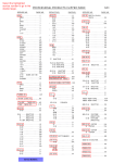
Z06 Rear Muffler and Butterfly Valve Vacuum Assembly Installation Overview: Exhaust Valve Operation (GM™ Service Manual) Exhaust Tail Pipe Flow Control System Description and Operation The Exhaust Flow Control (EFC) System enhances engine performance. The system has 2 modes of operation: Normal Mode When the vehicle is stationary with the engine running the exhaust flow control module (EFCM) commands the vacuum solenoid On, which supplies engine vacuum to both exhaust flow control valves. This causes the valves to close, diverting exhaust flow through a baffled path inside the mufflers. As vehicle speed increases, throttle position reaches 25 percent or greater and engine speed reaches 3500 RPM, the EFCM commands the vacuum solenoid off. This causes the valves to open, diverting exhaust flow through an un-baffled path inside the mufflers, thus enhancing engine performance. Competition Mode When traction control is driver disabled, vehicle speed increases, throttle position reaches 25 percent or greater and engine speed reaches 3000 RPM, the EFCM commands the vacuum solenoid off. This causes the valves to open; diverting exhaust flow through an un-baffled path inside the mufflers more frequently and at lower engine speeds. The system also delays exhaust valve activity during wide-open throttle acceleration to inhibit exhaust valve actuation when the accelerator pedal is released and reapplied while shifting gears. The EFCM has the ability to detect electrical malfunctions within the system. Any electrical malfunction detected will cause the system to be disabled and increased exhaust audibility. The system uses the engine control module (ECM), body control module (BCM), electronic brake control module (EBCM), EFCM, exhaust flow control valve vacuum solenoid, vacuum reservoir, vacuum lines, 2 exhaust flow control valves and the serial data circuit to perform the system functions. Page 1 of 13 Z06 Rear Muffler and Butterfly Valve Vacuum Assembly Installation Page 2 of 13 Z06 Rear Muffler and Butterfly Valve Vacuum Assembly Installation Call # GM Part # Description Qty 001 15837271 Valve, Intake Manifold Vacuum Check (Part of 002) 01 002 14047619 Valve, Intake Manifold Vacuum Check (Part of 001) (AC Delco #14047619) 01 003 10276208 Clip, Fuel Front Pipe 01 004 11514517 Nut, HEX w/CON SPR WA,M6X1,5.7THK,18 O.D.,9,7111M (Fuel Feed & Return Pipe 04 005 10288898 Clip, Fuel Feed & Return Pipe 01 006 15816225 Pipe, Exhaust Tail Pipe Cont Vacuum Front (3.163) 01 007 10276219 Retainer, Fuel Feed & Return Front Pipe 03 008 12522916 Retainer, Fuel Return Pipe FTG (Part of 9, 19) (BLUE) (INCLS INST SHT & RET) (USE WITH 5/16 TUBE, NYLON) 01 009 15782801 Pipe, Intake Manifold RR C/OVR (INCLUDES 8,10) 01 010 01648216 Clamp, worm gear, hex-slot screw ¼ X 5/8, 320 WIDE BAND, BLACK (Part of 9) (AC DELCO #1648216) 01 011 10284014 Bolt, Intake Manifold RR C/OVR PIPE (M6.3X1.27-25 HEX HD) (7.833) 02 012 11610324 Clamp, Loop, Single, DIA 9.5MM, C-TO-C 17.8, WIDTH 15.9, HOLE DIA 11.1 (INT MANIF TUBE) 02 013 15782803 Hose, Intake Manifold Tuning Valve Actuator (INCLS 14) 01 014 12040984 Clip, Evaporation Emission Canister Harness (Part of 13) (Black Polypropylene) (Holds 6MM CONVOLUTED CONDUIT) (2.383) 01 015 Cost Notes Harness, Body Front & I/P WRG (SEE GROUP 02.000 “WIRING HARNESS/INSTRUMENT PANEL & BODY” FOR DETAILED ILLUSTRATED VIEW) 016 15296305 Module, Exhaust Tail Pipe Flow Valve Control 01 017 03530297 Nut, HFH, M6X1, 5.85THK, 14.2 O.D., 10, Z0R (Intake Manifold Tuning Valve Vacuum Control Solenoid Valve) 01 018 15211319 Valve, Intake Manifold Tuning Vacuum Control Solenoid (Part of 19) 01 019 15782802 Solenoid, Intake Manifold Tuning Valve Actuator (INCLS 8, 18) 01 020 15973049 Tank, Exhaust Tail Pipe Flow Valve Vacuum Pipe Reservoir 01 021 11561319 Bolt, Exhaust Tail Pipe Flow Control Valve Vacuum Pipe Tank (Bolt, HEX w/INT TORX, W/FL WA, M6X1X17.5, 10MM SOC, T30 INT LOBE, 11MM THD) 02 15237510 F55 console switch 01 88988116 F55 female connector plug 01 89046833 Connector for Vacuum solenoid 01 Add-a-circuit 01 Totals Page 3 of 13 Manual override valves PEP BOYS Z06 Rear Muffler and Butterfly Valve Vacuum Assembly Installation Page 4 of 13 Z06 Rear Muffler and Butterfly Valve Vacuum Assembly Installation Part I: Bumper Removal (author: codename Bil Doe) Tools Needed: - T15 torx - 7mm socket wrench - 8mm socket wrench - 10mm socket wrench - flathead screwdriver This is the picture after everything is reassembled but it serves as a starting point. Make a checklist of all bolts removed and then lay them out in their respective positions off to the side just to make it easier during reinstallation. Page 5 of 13 Z06 Rear Muffler and Butterfly Valve Vacuum Assembly Installation Jack up and support the car. Remove the rear wheels and taillights. Lay out the tail lights from left to right. I noticed that they didn't fit well in the wrong hole. Use a T15 torx for each tail light screw (One screw per light on the top). Page 6 of 13 Z06 Rear Muffler and Butterfly Valve Vacuum Assembly Installation Remove the two 3" long plastic screws that attach the cover to the foam bumper. These are located behind the license plate and have square heads but you can use a flathead screwdriver to remove. Page 7 of 13 Z06 Rear Muffler and Butterfly Valve Vacuum Assembly Installation Remove 3 of the bolts on the back half of the fender liner. This will give you enough access to pull the liner out a little and reach the 3 lower nuts connecting the rear bumper to the quarter panel. There are 5 bolts total holding the bumper to each quarter panel along a black rail on each side. Use a 10mm socket wrench to remove the lowest bolt. The lowest is a nut/bolt combo and the second and third up are just nuts. The third is much higher than the first two (mid way up the quarter panel) so it takes a little more of a reach to get to. Page 8 of 13 Z06 Rear Muffler and Butterfly Valve Vacuum Assembly Installation Remove the 4th and 5th bolts easily through the outer tail light holes. They are very easy to see and are within 4" of each other. You can also see the side marker light that must be disconnected further below. Page 9 of 13 Z06 Rear Muffler and Butterfly Valve Vacuum Assembly Installation Using a 7mm socket, remove (8) hex head screws attaching the bumper to the car where it wraps under to the left and right of the mufflers. There are (4) screws per side. VERY IMPORTANT!!! Using a 10mm wrench with an elbow joint, remove the (2) bolts that hold the center of the bumper to the frame. The bolts are above the muffler tips and hold two metal L-brackets. There is a plastic washer between the L-bracket and the body so make sure not to lose this! (It’s much easier to take these two bolts rather than the two screws holding each L-bracket to the bumper) Page 10 of 13 Z06 Rear Muffler and Butterfly Valve Vacuum Assembly Installation DO NOT DRILL OUT THE RIVETS ON THE MANUAL TRUNK RELEASE LOCK!! Free the manual trunk release lock by disconnecting the cable from the inside. To do this, pop the trunk and pull the carpeting away from the lock mechanism. There are two plastic xmas tree pins holding the carpet down on each side of it. Though the picture is fuzzy, you will see where the cable end sits in a plastic u-shaped arm. Pull the arm to the passenger side of the car while sliding the cable end toward the driver's side and (with a little stretch) you will have enough to slide it out. Open the two metal "arms" hugging the excess cable and push the rubber grommet gently through the hole to the rear bumper. Page 11 of 13 Z06 Rear Muffler and Butterfly Valve Vacuum Assembly Installation With a T15 torx, remove the 6 torx screws across the inside of the top bumper. You will need to pop the hatch/trunk to do perform this step. Don't worry, the bumper won't fall as it rests on a lip and you have to lift it off the lip to remove it. Page 12 of 13 Z06 Rear Muffler and Butterfly Valve Vacuum Assembly Installation As far as I can remember, these are the connectors which must be disconnected to remove the bumper. Note: the wiring harness does not have to be unclipped from the bumper. It all can go as one piece saving a lot of time reinstalling. To access these connections, you will have to lift the bumper off the top lip and hold it while disconnecting. I made this a little easier by resting it temporarily on the muffler tips. a) Disconnect the two side marker lights in each quarter panel. There is just enough flexibility/room to remove these without loosening the panel. b) Disconnect the reverse lights on the bottom corners of the bumper c) Disconnect the 3rd brake light (I don't remember if this is connected to the harness that spans the length of the bumper or not d) Disconnect the main plug on the right side of the bumper. It is connected with a plastic hold down at the end of the ground strap inside the bumper. The ground strap is obvious so just follow it to the end until you see the connector. You can see the main plug on the right in this picture. It's coming through the rear with a thick rubber grommet to seal out moisture. Total time with removal/installation and addition of muffler parts + 2 trips to the store was 5 hours as a one-person job. Page 13 of 13