1
View Safety Info
Return to Master TOC
RETURN TO MAIN MENU
SVM177-A
V160-S & -T
October, 2007
For use with machines having Code Numbers: 10877, 10878
11031, 11032
Return to Master TOC
View Safety Info
Return to Master TOC
View Safety Info
Safety Depends on You
Lincoln arc welding and cutting
equipment is designed and built
with safety in mind. However, your
overall safety can be increased by
proper installation ... and thoughtful operation on your part. DO
NOT INSTALL, OPERATE OR
REPAIR THIS EQUIPMENT
WITHOUT READING THIS
MANUAL AND THE SAFETY
PRECAUTIONS CONTAINED
THROUGHOUT. And, most
importantly, think before you act
and be careful.
View Safety Info
Return to Master TOC
SERVICE MANUAL
Copyright © Lincoln Global Inc.
• World's Leader in Welding and Cutting Products •
• Sales and Service through Subsidiaries and Distributors Worldwide •
Cleveland, Ohio 44117-1199 U.S.A. TEL: 216.481.8100 FAX: 216.486.1751 WEB SITE: www.lincolnelectric.com
SAFETY
Return to Master TOC
i
i
WARNING
CALIFORNIA PROPOSITION 65 WARNINGS
Diesel engine exhaust and some of its constituents
The engine exhaust from this product contains
are known to the State of California to cause canchemicals known to the State of California to cause
cer, birth defects, and other reproductive harm.
cancer, birth defects, or other reproductive harm.
The Above For Gasoline Engines
The Above For Diesel Engines
ARC WELDING CAN BE HAZARDOUS. PROTECT YOURSELF AND OTHERS FROM POSSIBLE SERIOUS INJURY OR DEATH.
KEEP CHILDREN AWAY. PACEMAKER WEARERS SHOULD CONSULT WITH THEIR DOCTOR BEFORE OPERATING.
Return to Master TOC
Return to Master TOC
Return to Master TOC
Read and understand the following safety highlights. For additional safety information, it is strongly recommended that you
purchase a copy of “Safety in Welding & Cutting - ANSI Standard Z49.1” from the American Welding Society, P.O. Box 351040,
Miami, Florida 33135 or CSA Standard W117.2-1974. A Free copy of “Arc Welding Safety” booklet E205 is available from the
Lincoln Electric Company, 22801 St. Clair Avenue, Cleveland, Ohio 44117-1199.
BE SURE THAT ALL INSTALLATION, OPERATION, MAINTENANCE AND REPAIR PROCEDURES ARE
PERFORMED ONLY BY QUALIFIED INDIVIDUALS.
FOR ENGINE
powered equipment.
1.a. Turn the engine off before troubleshooting and maintenance
work unless the maintenance work requires it to be running.
____________________________________________________
1.b.Operate engines in open, well-ventilated
areas or vent the engine exhaust fumes
outdoors.
____________________________________________________
1.c. Do not add the fuel near an open flame welding arc or when the engine is running. Stop
the engine and allow it to cool before refueling to prevent spilled fuel from vaporizing on
contact with hot engine parts and igniting. Do
not spill fuel when filling tank. If fuel is spilled,
wipe it up and do not start engine until fumes
have been eliminated.
____________________________________________________
1.d. Keep all equipment safety guards, covers and devices in position and in good repair.Keep hands, hair, clothing and tools
away from V-belts, gears, fans and all other moving parts
when starting, operating or repairing equipment.
____________________________________________________
1.e. In some cases it may be necessary to remove safety
guards to perform required maintenance. Remove
guards only when necessary and replace them when the
maintenance requiring their removal is complete.
Always use the greatest care when working near moving
parts.
___________________________________________________
1.f. Do not put your hands near the engine fan.
Do not attempt to override the governor or
idler by pushing on the throttle control rods
while the engine is running.
___________________________________________________
1.g. To prevent accidentally starting gasoline engines while
turning the engine or welding generator during maintenance
work, disconnect the spark plug wires, distributor cap or
magneto wire as appropriate.
1.h. To avoid scalding, do not remove the
radiator pressure cap when the engine is
hot.
ELECTRIC AND
MAGNETIC FIELDS
may be dangerous
2.a. Electric current flowing through any conductor causes
localized Electric and Magnetic Fields (EMF). Welding
current creates EMF fields around welding cables and
welding machines
2.b. EMF fields may interfere with some pacemakers, and
welders having a pacemaker should consult their physician
before welding.
2.c. Exposure to EMF fields in welding may have other health
effects which are now not known.
2.d. All welders should use the following procedures in order to
minimize exposure to EMF fields from the welding circuit:
2.d.1. Route the electrode and work cables together - Secure
them with tape when possible.
2.d.2. Never coil the electrode lead around your body.
2.d.3. Do not place your body between the electrode and
work cables. If the electrode cable is on your right
side, the work cable should also be on your right side.
2.d.4. Connect the work cable to the workpiece as close as
possible to the area being welded.
2.d.5. Do not work next to welding power source.
Mar ʻ95
Return to Master TOC
Return to Master TOC
ii
SAFETY
ELECTRIC SHOCK can kill.
3.a. The electrode and work (or ground) circuits
are electrically “hot” when the welder is on.
Do not touch these “hot” parts with your bare
skin or wet clothing. Wear dry, hole-free
gloves to insulate hands.
3.b. Insulate yourself from work and ground using dry insulation.
Make certain the insulation is large enough to cover your full
area of physical contact with work and ground.
In addition to the normal safety precautions, if welding
must be performed under electrically hazardous
conditions (in damp locations or while wearing wet
clothing; on metal structures such as floors, gratings or
scaffolds; when in cramped positions such as sitting,
kneeling or lying, if there is a high risk of unavoidable or
accidental contact with the workpiece or ground) use
the following equipment:
• Semiautomatic DC Constant Voltage (Wire) Welder.
• DC Manual (Stick) Welder.
• AC Welder with Reduced Voltage Control.
3.c. In semiautomatic or automatic wire welding, the electrode,
electrode reel, welding head, nozzle or semiautomatic
welding gun are also electrically “hot”.
3.d. Always be sure the work cable makes a good electrical
connection with the metal being welded. The connection
should be as close as possible to the area being welded.
3.e. Ground the work or metal to be welded to a good electrical
(earth) ground.
3.f. Maintain the electrode holder, work clamp, welding cable and
welding machine in good, safe operating condition. Replace
damaged insulation.
Return to Master TOC
3.g. Never dip the electrode in water for cooling.
3.h. Never simultaneously touch electrically “hot” parts of
electrode holders connected to two welders because voltage
between the two can be the total of the open circuit voltage
of both welders.
3.i. When working above floor level, use a safety belt to protect
yourself from a fall should you get a shock.
3.j. Also see Items 6.c. and 8.
ARC RAYS can burn.
4.a.
ii
Use a shield with the proper filter and cover
plates to protect your eyes from sparks and
the rays of the arc when welding or observing
open arc welding. Headshield and filter lens
should conform to ANSI Z87. I standards.
4.b. Use suitable clothing made from durable flame-resistant
material to protect your skin and that of your helpers from
the arc rays.
4.c. Protect other nearby personnel with suitable, non-flammable
screening and/or warn them not to watch the arc nor expose
themselves to the arc rays or to hot spatter or metal.
FUMES AND GASES
can be dangerous.
5.a. Welding may produce fumes and gases
hazardous to health. Avoid breathing these
fumes and gases.When welding, keep
your head out of the fume. Use enough
ventilation and/or exhaust at the arc to keep
fumes and gases away from the breathing zone. When
welding with electrodes which require special
ventilation such as stainless or hard facing (see
instructions on container or MSDS) or on lead or
cadmium plated steel and other metals or coatings
which produce highly toxic fumes, keep exposure as
low as possible and below Threshold Limit Values (TLV)
using local exhaust or mechanical ventilation. In
confined spaces or in some circumstances, outdoors, a
respirator may be required. Additional precautions are
also required when welding on galvanized steel.
5. b. The operation of welding fume control equipment is affected
by various factors including proper use and positioning of the
equipment, maintenance of the equipment and the specific
welding procedure and application involved. Worker exposure level should be checked upon installation and periodically thereafter to be certain it is within applicable OSHA PEL
and ACGIH TLV limits.
5.c. Do not weld in locations near chlorinated hydrocarbon vapors
coming from degreasing, cleaning or spraying operations.
The heat and rays of the arc can react with solvent vapors to
form phosgene, a highly toxic gas, and other irritating products.
5.d. Shielding gases used for arc welding can displace air and
cause injury or death. Always use enough ventilation,
especially in confined areas, to insure breathing air is safe.
Return to Master TOC
5.e. Read and understand the manufacturerʼs instructions for this
equipment and the consumables to be used, including the
material safety data sheet (MSDS) and follow your
employerʼs safety practices. MSDS forms are available from
your welding distributor or from the manufacturer.
5.f. Also see item 1.b.
Aug ʻ06
Return to Master TOC
iii
WELDING SPARKS can
cause fire or explosion.
SAFETY
6.a. Remove fire hazards from the welding area.
If this is not possible, cover them to prevent
the welding sparks from starting a fire.
Remember that welding sparks and hot
materials from welding can easily go through small cracks
and openings to adjacent areas. Avoid welding near
hydraulic lines. Have a fire extinguisher readily available.
7.b. Always keep cylinders in an upright position securely
chained to an undercarriage or fixed support.
6.d. Do not heat, cut or weld tanks, drums or containers until the
proper steps have been taken to insure that such procedures
will not cause flammable or toxic vapors from substances
inside. They can cause an explosion even though they have
been “cleaned”. For information, purchase “Recommended
Safe Practices for the Preparation for Welding and Cutting of
Containers and Piping That Have Held Hazardous
Substances”, AWS F4.1 from the American Welding Society
(see address above).
7.d. Never allow the electrode, electrode holder or any other
electrically “hot” parts to touch a cylinder.
Return to Master TOC
6.e. Vent hollow castings or containers before heating, cutting or
welding. They may explode.
6.f. Sparks and spatter are thrown from the welding arc. Wear oil
free protective garments such as leather gloves, heavy shirt,
cuffless trousers, high shoes and a cap over your hair. Wear
ear plugs when welding out of position or in confined places.
Always wear safety glasses with side shields when in a
welding area.
Return to Master TOC
7.a. Use only compressed gas cylinders
containing the correct shielding gas for the
process used and properly operating
regulators designed for the gas and
pressure used. All hoses, fittings, etc. should be suitable for
the application and maintained in good condition.
6.b. Where compressed gases are to be used at the job site,
special precautions should be used to prevent hazardous
situations. Refer to “Safety in Welding and Cutting” (ANSI
Standard Z49.1) and the operating information for the
equipment being used.
6.c. When not welding, make certain no part of the electrode
circuit is touching the work or ground. Accidental contact can
cause overheating and create a fire hazard.
Return to Master TOC
CYLINDER may explode
if damaged.
iii
6.g. Connect the work cable to the work as close to the welding
area as practical. Work cables connected to the building
framework or other locations away from the welding area
increase the possibility of the welding current passing
through lifting chains, crane cables or other alternate circuits.
This can create fire hazards or overheat lifting chains or
cables until they fail.
6.h. Also see item 1.c.
7.c. Cylinders should be located:
• Away from areas where they may be struck or subjected to
physical damage.
• A safe distance from arc welding or cutting operations and
any other source of heat, sparks, or flame.
7.e. Keep your head and face away from the cylinder valve outlet
when opening the cylinder valve.
7.f. Valve protection caps should always be in place and hand
tight except when the cylinder is in use or connected for
use.
7.g. Read and follow the instructions on compressed gas
cylinders, associated equipment, and CGA publication P-l,
“Precautions for Safe Handling of Compressed Gases in
Cylinders,” available from the Compressed Gas Association
1235 Jefferson Davis Highway, Arlington, VA 22202.
FOR ELECTRICALLY
powered equipment.
8.a. Turn off input power using the disconnect
switch at the fuse box before working on
the equipment.
8.b. Install equipment in accordance with the U.S. National
Electrical Code, all local codes and the manufacturerʼs
recommendations.
8.c. Ground the equipment in accordance with the U.S. National
Electrical Code and the manufacturerʼs recommendations.
Mar ʻ95
Return to Master TOC
Return to Master TOC
Return to Master TOC
Return to Master TOC
iv
PRÉCAUTIONS DE SÛRETÉ
SAFETY
Pour votre propre protection lire et observer toutes les instructions
et les précautions de sûreté specifiques qui parraissent dans ce
manuel aussi bien que les précautions de sûreté générales suivantes:
Sûreté Pour Soudage A LʼArc
1. Protegez-vous contre la secousse électrique:
a. Les circuits à lʼélectrode et à la piéce sont sous tension
quand la machine à souder est en marche. Eviter toujours
tout contact entre les parties sous tension et la peau nue
ou les vétements mouillés. Porter des gants secs et sans
trous pour isoler les mains.
b. Faire trés attention de bien sʼisoler de la masse quand on
soude dans des endroits humides, ou sur un plancher metallique ou des grilles metalliques, principalement dans
les positions assis ou couché pour lesquelles une grande
partie du corps peut être en contact avec la masse.
c. Maintenir le porte-électrode, la pince de masse, le câble de
soudage et la machine à souder en bon et sûr état defonctionnement.
d.Ne jamais plonger le porte-électrode dans lʼeau pour le
refroidir.
e. Ne jamais toucher simultanément les parties sous tension
des porte-électrodes connectés à deux machines à souder
parce que la tension entre les deux pinces peut être le total
de la tension à vide des deux machines.
f. Si on utilise la machine à souder comme une source de
courant pour soudage semi-automatique, ces precautions
pour le porte-électrode sʼapplicuent aussi au pistolet de
soudage.
2. Dans le cas de travail au dessus du niveau du sol, se protéger
contre les chutes dans le cas ou on recoit un choc. Ne jamais
enrouler le câble-électrode autour de nʼimporte quelle partie du
corps.
3. Un coup dʼarc peut être plus sévère quʼun coup de soliel, donc:
a. Utiliser un bon masque avec un verre filtrant approprié ainsi
quʼun verre blanc afin de se protéger les yeux du rayonnement de lʼarc et des projections quand on soude ou
quand on regarde lʼarc.
b. Porter des vêtements convenables afin de protéger la peau
de soudeur et des aides contre le rayonnement de lʻarc.
c. Protéger lʼautre personnel travaillant à proximité au
soudage à lʼaide dʼécrans appropriés et non-inflammables.
4. Des gouttes de laitier en fusion sont émises de lʼarc de
soudage. Se protéger avec des vêtements de protection libres
de lʼhuile, tels que les gants en cuir, chemise épaisse, pantalons sans revers, et chaussures montantes.
5. Toujours porter des lunettes de sécurité dans la zone de
soudage. Utiliser des lunettes avec écrans lateraux dans les
zones où lʼon pique le laitier.
iv
6. Eloigner les matériaux inflammables ou les recouvrir afin de
prévenir tout risque dʼincendie dû aux étincelles.
7. Quand on ne soude pas, poser la pince à une endroit isolé de
la masse. Un court-circuit accidental peut provoquer un
échauffement et un risque dʼincendie.
8. Sʼassurer que la masse est connectée le plus prés possible de
la zone de travail quʼil est pratique de le faire. Si on place la
masse sur la charpente de la construction ou dʼautres endroits
éloignés de la zone de travail, on augmente le risque de voir
passer le courant de soudage par les chaines de levage,
câbles de grue, ou autres circuits. Cela peut provoquer des
risques dʼincendie ou dʼechauffement des chaines et des
câbles jusquʼà ce quʼils se rompent.
9. Assurer une ventilation suffisante dans la zone de soudage.
Ceci est particuliérement important pour le soudage de tôles
galvanisées plombées, ou cadmiées ou tout autre métal qui
produit des fumeés toxiques.
10. Ne pas souder en présence de vapeurs de chlore provenant
dʼopérations de dégraissage, nettoyage ou pistolage. La
chaleur ou les rayons de lʼarc peuvent réagir avec les vapeurs
du solvant pour produire du phosgéne (gas fortement toxique)
ou autres produits irritants.
11. Pour obtenir de plus amples renseignements sur la sûreté, voir
le code “Code for safety in welding and cutting” CSA Standard
W 117.2-1974.
PRÉCAUTIONS DE SÛRETÉ POUR
LES MACHINES À SOUDER À
TRANSFORMATEUR ET À
REDRESSEUR
1. Relier à la terre le chassis du poste conformement au code de
lʼélectricité et aux recommendations du fabricant. Le dispositif
de montage ou la piece à souder doit être branché à une
bonne mise à la terre.
2. Autant que possible, Iʼinstallation et lʼentretien du poste seront
effectués par un électricien qualifié.
3. Avant de faires des travaux à lʼinterieur de poste, la debrancher à lʼinterrupteur à la boite de fusibles.
4. Garder tous les couvercles et dispositifs de sûreté à leur place.
Mar ʻ93
I
- MASTER TABLE OF CONTENTS FOR ALL SECTIONS RETURN TO MAIN INDEX
RETURN TO MAIN MENU
Page
Safety . . . . . . . . . . . . . . . . . . . . . . . . . . . . . . . . . . . . . . . . . . . . . . . . . . . . . . . . . . . . . . . . . . . . . . . . . . .i-iv
Installation (V160-S) . . . . . . . . . . . . . . . . . . . . . . . . . . . . . . . . . . . . . . . . . . . . . . . . . . . . . . . . . .Section A
Installation (V160-T) . . . . . . . . . . . . . . . . . . . . . . . . . . . . . . . . . . . . . . . . . . . . . . . . . . . . . . . . .Section AA
Operation (V160-S) . . . . . . . . . . . . . . . . . . . . . . . . . . . . . . . . . . . . . . . . . . . . . . . . . . . . . . . . . . .Section B
Operation (V160-T) . . . . . . . . . . . . . . . . . . . . . . . . . . . . . . . . . . . . . . . . . . . . . . . . . . . . . . . . . .Section BB
Accessories (V160-S) . . . . . . . . . . . . . . . . . . . . . . . . . . . . . . . . . . . . . . . . . . . . . . . . . . . . . . . . .Section C
Accessories (V160-T) . . . . . . . . . . . . . . . . . . . . . . . . . . . . . . . . . . . . . . . . . . . . . . . . . . . . . . .Section CC
Maintenance (V160-S) . . . . . . . . . . . . . . . . . . . . . . . . . . . . . . . . . . . . . . . . . . . . . . . . . . . . . . . .Section D
Maintenance (V160-T) . . . . . . . . . . . . . . . . . . . . . . . . . . . . . . . . . . . . . . . . . . . . . . . . . . . . . . .Section DD
Theory of Operation (V160-S) . . . . . . . . . . . . . . . . . . . . . . . . . . . . . . . . . . . . . . . . . . . . . . . . . .Section E
Theory of Operation (V160-T) . . . . . . . . . . . . . . . . . . . . . . . . . . . . . . . . . . . . . . . . . . . . . . . . .Section EE
Troubleshooting and Repair (V160-S / T) . . . . . . . . . . . . . . . . . . . . . . . . . . . . . . . . . . . . . . . . .Section F
Electrical Diagrams (V160-S / T) . . . . . . . . . . . . . . . . . . . . . . . . . . . . . . . . . . . . . . . . . . . . . . . .Section G
Parts Manual (V160-S / T) . . . . . . . . . . . . . . . . . . . . . . . . . . . . . . . . . . . . . . . . . . . . . . . . . . . . . . . . .P-403
V160-S & -T
I
Return to Master TOC
A-1
TABLE OF CONTENTS - INSTALLATION SECTION V160-S
A-1
Installation . . . . . . . . . . . . . . . . . . . . . . . . . . . . . . . . . . . . . . . . . . . . . . . . . . . . . . . . . . . . . . . . . . . . . . . . . . . . .A-1
Technical Specifications . . . . . . . . . . . . . . . . . . . . . . . . . . . . . . . . . . . . . . . . . . . . . . . . . . . . . . . . . . . . . . . .A-2
Safety Precautions . . . . . . . . . . . . . . . . . . . . . . . . . . . . . . . . . . . . . . . . . . . . . . . . . . . . . . . . . . . . . . . . . . . .A-3
Select Suitable Location . . . . . . . . . . . . . . . . . . . . . . . . . . . . . . . . . . . . . . . . . . . . . . . . . . . . . . . . . . . . . . . .A-3
Stacking . . . . . . . . . . . . . . . . . . . . . . . . . . . . . . . . . . . . . . . . . . . . . . . . . . . . . . . . . . . . . . . . . . . . . . . . . . . .A-3
Return to Master TOC
Tilting . . . . . . . . . . . . . . . . . . . . . . . . . . . . . . . . . . . . . . . . . . . . . . . . . . . . . . . . . . . . . . . . . . . . . . . . . . . . . .A-3
Input Connections . . . . . . . . . . . . . . . . . . . . . . . . . . . . . . . . . . . . . . . . . . . . . . . . . . . . . . . . . . . . . . . . . . . .A-3
Ground Connection . . . . . . . . . . . . . . . . . . . . . . . . . . . . . . . . . . . . . . . . . . . . . . . . . . . . . . . . . . . . . . . .A-3/A-4
Output Connections . . . . . . . . . . . . . . . . . . . . . . . . . . . . . . . . . . . . . . . . . . . . . . . . . . . . . . . . . . . . . . . . . . .A-5
Output and Gas Connection for Tig Welding . . . . . . . . . . . . . . . . . . . . . . . . . . . . . . . . . . . . . . . . . . . . . . . .A-5
Output Connection for Stick Welding . . . . . . . . . . . . . . . . . . . . . . . . . . . . . . . . . . . . . . . . . . . . . . . . . . . . . .A-5
Quick Disconnect Plug . . . . . . . . . . . . . . . . . . . . . . . . . . . . . . . . . . . . . . . . . . . . . . . . . . . . . . . . . . . . . .A-6
Output Connection for Tig Welding . . . . . . . . . . . . . . . . . . . . . . . . . . . . . . . . . . . . . . . . . . . . . . . . . . . . .A-6
Return to Master TOC
Return to Master TOC
Remote Control Connection . . . . . . . . . . . . . . . . . . . . . . . . . . . . . . . . . . . . . . . . . . . . . . . . . . . . . . . . . .A-6
V160-S & -T
INSTALLATION
Return to Master TOC
Return to Section TOC
A-2
TECHNICAL SPECIFICATION V160-S
INPUT - SINGLE PHASE ONLY
Input Voltages / 50 /60 Hz.
115 V (20 A branch)
115 V (30 A branch)
230 V
Output Amps
Duty Cycle
Return to Master TOC
Max. Input Current at rated Output
RATED OUTPUT
Output Volts
60 (Stick)
90 (TIG)
100%
Return to Section TOC
A-2
80 (Stick)
110 (TIG)
160 (Stick)
160 (TIG)
35%
130 (Stick)
130 (TIG)
100%
Output Current Range
5-160 Amps
20 A
25 A
34 A
Input Circuit
22.4
13.6
115V (20A Branch)
26.4
16.4
230V (30A Branch)
23.2
14.4
115V (30A Branch)
25.2
15.2
230V (30A Branch)
OUTPUT
Maximum Open Circuit Voltage
48 Volts Max.
Type of Output
DC
Return to Section TOC
Return to Master TOC
Return to Section TOC
Return to Master TOC
RECOMMENDED INPUT WIRE AND FUSE SIZES FOR MAXIMUM RATED OUTPUT
INPUT VOLTAGE /
FREQUENCY (HZ)
230/50/60
Height
12.6 in.
320 mm
Width
7.9 in.
200 mm
TYPE S, SO ST, STO, OR EXTRA
HARD USAGE INPUT CORD AWG
#12
PHYSICAL DIMENSIONS
Depth
16.9 in.
430 mm
TEMPERATURE RANGES
MAXIMUM TIME-DELAY CIRCUIT
BREAKER OR FUSE SIZE (AMPS)
30
Weight
Approx. 24.2lbs.
11 kgs.
STORAGE TEMPERATURE RANGE
-50°C to +85°C
OPERATING TEMPERATURE RANGE
-20°C to +40°C
V160-S & -T
INSTALLATION
Return to Master TOC
Return to Master TOC
Return to Master TOC
Return to Section TOC
Return to Section TOC
Return to Section TOC
A-3
Read entire installation section before starting
installation.
SAFETY PRECAUTIONS
WARNING
ELECTRIC SHOCK can kill.
• Only qualified personnel should perform this installation.
• Disconnect input power by removing
plug from receptacle before working
inside V160-S. Allow machine to sit for
5 minutes minimum to allow the power capacitors
to discharge before working inside this equipment.
• Insulate yourself from the work and ground.
• Always wear dry insulating gloves.
• Always connect the V160-S to a power supply
grounded according to the National Electrical Code
and local codes.
-----------------------------------------------------------SELECT SUITABLE LOCATION
This machine will operate in harsh environments.
However, it is important that simple preventative measures are followed to assure long life and reliable operation.
• Do not place or operate this machine on a surface
with an incline greater than 15° from horizontal.
• This machine must be located where there is free circulation of clean air without restrictions for air movement to and from the air vents. Do not cover the
machine with paper, cloth or rags when switched on.
• Dirt and dust that can be drawn into the machine
should be kept to a minimum.
• Keep the machine dry and do not place it on wet
ground or in puddles.
• When operated in ambient temperatures greater
than 40°C, the output duty cycle may be reduced.
Return to Master TOC
Return to Section TOC
• Do not mount over combustible surfaces.
STACKING
The Invertec V160-S cannot be stacked.
A-3
TILTING
Place the machine directly on a secure, level surface.
The machine may topple over if this procedure is not
followed.
INPUT CONNECTIONS
WARNING
ELECTRIC SHOCK can kill.
• Have a qualified electrician install
and service this equipment.
• Disconnect input power by removing
plug from receptacle before working
inside V160-S. Allow machine to sit for
5 minutes minimum to allow the power capacitors
to discharge before working inside this equipment.
• Do not touch electrically live parts.
-----------------------------------------------------------------------
GROUND CONNECTION
The frame of the welder must be grounded. A ground
terminal marked with the symbol is
located on the under panel for this purpose. See your local and national electrical codes for proper grounding methods.
CAUTION
A grounding conductor is supplied in the input
cord, it is important that the supply receptacle
ground is connected.
-----------------------------------------------------------------------
WARNING
This installation should be performed by a qualified electrician to ensure correct connections of
the leads to the plug spades.
• The electrical system must be made by skilled
technicians with the specific professional and
technical qualifications and in compliance with
the regulations in force in the country where the
equipment is installed.
• The welding power source supply cable is provided with a green or yellow/green wire that must
ALWAYS be earthed. This green or yellow/green
wire must NEVER be used with other voltage conductors.
• lnstall only plugs that confirm with safety regulations.
------------------------------------------------------------------------
V160-S & -T
Return to Master TOC
Return to Section TOC
A-4
INSTALLATION
Fuse the input circuit with time delay fuses marked “D”
or delay type1 circuit breakers. Using fuses or circuit
breakers smaller than recommended may result in
“nuisance” shut-offs from welder inrush currents even
if not welding at high currents.
1
Also called “inverse time” or “thermal/magnetic” circuit breakers.
These circuit breakers have a delay in tripping action that decreases
as the magnitude of the current increases.
The Invertec V160-S is recommended for use on an
individual branch circuit.
Return to Master TOC
Return to Section TOC
115V INPUT
The rated output of the V160-S is available when connected to a 30A branch circuit. When connected to a
branch circuit with lower ampacity, lower welding current and duty cycle must be used. An output guide is
provided below. The values are approximate and must
be adjusted downward if the fuse or circuit breaker
trips off. Other loads on the circuit and fuse/circuit
breaker characteristics will affect the available output.
Do not exceed these welding conditions:
15A plug on a 15A branch
10% duty cycle
Stick: 65A
TIG:
95A
Return to Master TOC
Return to Master TOC
Return to Section TOC
Return to Section TOC
When the ARFU has been activated due to an input
over current condition, the output will be turned off and
the green Power LED will blink indicating an over-current condition. This condition usually occurs when the
unit is operated beyond its rated duty cycle. The unit
will self-restore after a short time and will be ready for
normal operation once the green Power LED stops
blinking and remains on.
NOTE: The ARFU replaces a fuse (F2) that was used
in older V160ʼs.
WARNING
• Failure to wire as instructed may cause personal
injury or damage to equipment. To be installed or
checked by an electrician or qualified person
only.
---------------------------------------------------------------------------
230V INPUT
To achieve the full output capacity of the V160-S,
230VAC inputs should be used. The change over is
accomplished by replacing the 115VAC plug with a 30
Amp 230VAC plug (NEMA 6-30P).
ATTACHMENT PLUG
In all cases, the green or green/yellow grounding wire
must be connected to the grounding pin of the plug, usually identified by a green screw.
15A plug on a 20A branch
10% duty cycle
Stick: 75A
TIG:
105A
All attachment plugs must comply with the Standard for
Attachment Plugs and Receptacles, UL498.
20A plug on a 20A branch
10% duty cycle
Stick: 85A
TIG:
120A
The product is considered acceptable for use only when
an attachment plug as specified is properly attached to
the supply cord.
The Invertec V160-S is provided with a 115/230V
cable, 6.6ft.(2m) in length, with a 15Amp 5-15P plug
molded onto the cord.
The V160-S is supplied with an additional 20A plug that
can replace the 15A plug to achieve higher output. To
install the supplied 20A plug:
Connect the white (neutral) wire under terminal clamp
with silver screw, and black (hot) wire under terminal
clamp with brass screw. Connect green wire under terminal clamp with green screw.
ARFU (Auto-Restore Fuse)
A-4
The dual input voltage machine is provided with an
ARFU device. It only operates when the input is connected to an 115V supply and protects from input over
current conditions.
The Invertec V160-S will auto reconnect to either 115V
or 230V supplies.
ENGINE DRIVEN GENERATOR
For use on engine drives, keep in mind the above input
draw restrictions and the following precaution.
The Invertec V160-S can be operated on engine driven
generators as long as the 230 volt auxiliary meets the
following conditions:
• The AC waveform peak voltage is below 400 volts*.
• The AC waveform frequency is between 45 and
65Hz.
• The RMS voltage of the AC waveform is always
greater than 208VAC *.
* for 115 VAC input divide these values in half.
The following Lincoln engine drives meet these conditions when run in the high idle mode:
V160-S & -T
INSTALLATION
Return to Master TOC
Return to Section TOC
A-5
• Ranger 250,305
• Commander 300, 400, & 500
Many engine drives do not meet these conditions (eg
Miller Bobcats, etc). Operation of the Invertec V160-S
is not recommended on engine drives not conforming
to these conditions. Such combinations may overvoltage the Invertec V160-S power source.
WARNING
OUTPUT CONNECTIONS
Return to Master TOC
Return to Section TOC
ELECTRIC SHOCK can kill.
• Insulate yourself from work and ground.
• Turn the input line Switch on the Invertec V160S “off” before connecting or disconnecting output cables or other equipment.
Return to Section TOC
Return to Master TOC
Return to Master TOC
----------------------------------------------------------The Work Cable and Electrode Cable are supplied with
the welder. To connect the cables,turnthe PowerSwitch
“OFF”.
Return to Section TOC
This unit does not include a TIG torch, but one may be
purchased separately. The Lincoln (K1781-7 PTA-9FV,
K1782-11 PTA-17FV) and (K1782-6, K1782-8 PTA17V) are recommended for use with this machine for
this purpose; however, any similar TIG torch can be
used. To attach the Twist-Mate Plug to a Lincoln Torch,
slide the rubber boot onto the torch cable (enlarge the
boot opening if necessary), screw the fitting on the
torch cable into the brass connector snugly and slide
the boot back over the brass connector.
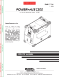
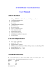
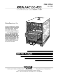
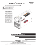
OUTPUT CONNECTION
WELDING (FIGURE A.2)
FIGURE A.2
OUTPUT AND GAS CONNECTION FOR
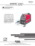
TIG WELDING (FIGURE A.1)
FIGURE A.1
GAS HOSE NOZZLE
WORK CABLE
STICK
ELECTRODE
HOLDER
First determine the proper electrode polarity for the
electrode to be used. Consult the electrode data for
this information. Then connect the output cables to the
output terminals corresponding to this polarity. For
instance, for DC(+) welding, connect the electrode
cable (which is connected to the electrode holder) to
the “+” output terminal and the work cable (which is
connected to the work clamp) to the “-” output terminal.
Insert the connector with the key lining up with the key
way, and rotate approximately 1/4 turn clockwise; until
the connection is snug. Do not over tighten.
TIG TORCH
WORK CABLE
FOR
WORK CLAMP
• Keep the electrode holder and
cable insulation in good condition.
• Do not touch electrically live parts
or electrode with skin or wet
clothing.
A-5
WORK CLAMP
V160-S & -T
INSTALLATION
Return to Master TOC
Return to Section TOC
A-6
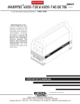
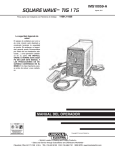
QUICK DISCONNECT PLUG (FOR STICK ELECTRODE CABLE)
A quick disconnect system is used for the welding
cable connections. The stick electrode cable will need
to have a plug attached.
1. Cut off welding cable lug, if present.
2. Remove .75 in. (19mm) of welding cable insulation.
3. Slide rubber boot onto cable end. The boot end
may be trimmed to match the cable diameter. Use
soap or other nonpetroleum-based lubricant to help
slide the boot over the cable, if needed.
BOOT
WELDING CABLE
.75 in.
Return to Master TOC
Return to Section TOC
19 mm
TRIM, IF REQ'D
TO FIT OVER CABLE
4. Cut 45-50% of the copper strands back 1/4” (6
mm).
REMOTE CONTROL CONNECTION
A remote control receptacle is provided on the lower
center case front of the welder for connecting a remote
control to the machine. The V160-S will automatically
sense if a remote control connection is made. In Lift
TIG mode (GTAW), WITHOUT a remote control device
connected to the V160-S, the output will come on automatically. WITH a remote control device connected to
the unit, the output will need to be triggered, i.e. a Foot
Amptrol. Refer to the Optional Accessories section of
this manual for available remote controls.
The following items can be connected to the 6 pin
socket on the front panel:
• Remote control potentiometer (K857) for Stick welding.
• Remote Foot Amptrol (K870), Hand Amptrol (K963-3).
WELDING CABLE
.25 in.
6 mm
5. Fold copper strands over cut strands and insert into
ferrule.
COPPER FERRULE
Return to Master TOC
Return to Master TOC
Return to Section TOC
WELDING CABLE
Return to Section TOC
A-6
.50 in. max
12 mm max.
SET SCREW
BRASS PLUG
6. Slide the copper ferrule into the brass plug.
7. Tighten set screw to collapse copper tube. Screw
must apply pressure against welding cable. The top
of the set screw will be well below the surface of the
brass plug after tightening.
COPPER TUBE
OUTPUT CONNECTION FOR TIG WELDING
A one piece Gas Valve Tig Torch is recommended for
use with the V160-S. A K960-1 Tig Torch adapter is
required. See Accessories Section.
V160-S & -T
Return to Master TOC
B-1
TABLE OF CONTENTS - OPERATION SECTION
B-1
Operation . . . . . . . . . . . . . . . . . . . . . . . . . . . . . . . . . . . . . . . . . . . . . . . . . . . . . . . . . . . . . . . . . . . . . . . . . . . . . .B-1
Safety Precautions . . . . . . . . . . . . . . . . . . . . . . . . . . . . . . . . . . . . . . . . . . . . . . . . . . . . . . . . . . . . . . . . . . . .B-2
General Description . . . . . . . . . . . . . . . . . . . . . . . . . . . . . . . . . . . . . . . . . . . . . . . . . . . . . . . . . . . . . . . . . . .B-2
Welding Capability . . . . . . . . . . . . . . . . . . . . . . . . . . . . . . . . . . . . . . . . . . . . . . . . . . . . . . . . . . . . . . . . . . . .B-2
Limitations . . . . . . . . . . . . . . . . . . . . . . . . . . . . . . . . . . . . . . . . . . . . . . . . . . . . . . . . . . . . . . . . . . . . . . . . . .B-2
Controls and Settings . . . . . . . . . . . . . . . . . . . . . . . . . . . . . . . . . . . . . . . . . . . . . . . . . . . . . . . . . . . . . .B-3/B-4
DIP Switch Functions (Service Information) . . . . . . . . . . . . . . . . . . . . . . . . . . . . . . . . . . . . . . . . . . . . . . . . .B-5
DIP Switch 1: Machine Type . . . . . . . . . . . . . . . . . . . . . . . . . . . . . . . . . . . . . . . . . . . . . . . . . . . . . . . . .B-5
DIP Switch 6: European/USA Machine Configuration . . . . . . . . . . . . . . . . . . . . . . . . . . . . . . . . . . . . . .B-6
Return to Master TOC
Return to Master TOC
Return to Master TOC
Rear Control Panel . . . . . . . . . . . . . . . . . . . . . . . . . . . . . . . . . . . . . . . . . . . . . . . . . . . . . . . . . . . . . . . . . . . .B-3
V160-S & -T
OPERATION
Return to Master TOC
Return to Section TOC
B-2
Read and understand this entire section before
operating your machine.
SAFETY INSTRUCTIONS
WARNING
ELECTRIC SHOCK can kill.
• Do not touch electrically live parts such
as output terminals or internal wiring.
• Insulate yourself from the work and ground.
Return to Master TOC
Return to Section TOC
• Always wear dry insulating gloves.
____________________________________
FUMES AND GASES
can be dangerous.
• Keep your head out of fumes.
• Use ventilation or exhaust to
remove fumes from breathing
zone.
Return to Master TOC
The Invertec V160-S is an industrial 160 amp arc welding power source which utilizes single phase input
power, to produce constant current output. The welding response of this Invertec has been optimized for
stick (SMAW) and Touch Start TIG (GTAW). The unit is
ideal for industrial applications where portability is
important.
The Invertec V160-S is recommended for stick welding
with such popular electrodes as Fleetweld 35,
Fleetweld 37, Fleetweld 180 and LH 78. It features
adjustable arc control to adjust the arc force and start.
The Invertec V160-S performs DC Touch Start Tig
Starting with excellent results.
WELDING CAPABILITY
The Invertec V160-S is rated at 160 amps, 26.4 volts,
at 35% duty cycle on a ten minute basis. It is capable
of higher duty cycles at lower output currents. It is
capable of 130 amps, 25.2 volts at at 100% duty
cycle(1). If the duty cycle is exceeded, a thermal protector will shut off the output until the machine cools.
See Technical Specifications in A-1 for other rated outputs.
The Invertec V160-S is recommended for stick welding
with such popular electrodes as Fleetweld® 35,
Fleetweld 37, Fleetweld 180 and Jet-LH 78 MR. It features adjustable arc control to adjust the arc force and
start.
WELDING, CUTTING and
GOUGING SPARKS
can cause fire or explosion
Return to Section TOC
GENERAL DESCRIPTION
• Keep flammable material away.
• Do not weld, cut or gouge on
containers that have held combustibles.
ARC RAYS
can burn.
LIMITATIONS
The V160-S is not recommended for pipe thawing.
(1)When
Return to Master TOC
• Wear eye, ear and body
protection.
Return to Section TOC
B-2
____________________________________
Observe additional guidelines detailed in the beginning
of this manual.
Only qualified personnel should operate this equipment. Observe all safety information throughout this
manual.
V160-S & -T
connected to 230VAC inputs.
OPERATION
Return to Master TOC
Return to Master TOC
Return to Section TOC
Return to Section TOC
B-3
REAR CONTROL PANEL
1. Power Switch: Controls the input power to the
machine. Make sure the machine is properly connected to the input supply before turning the
machine on.(See Figure B.1)
2. Fan: The cooling fan will turn ON when the machine
is turned ON and it will continue to run whenever the
output of the machine is ON. If the output of the
machine is OFF for more than five minutes, the fan
will turn OFF. This reduces the amount of dirt that is
deposited inside the machine and reduces power
consumption.(See Figure B.1)
Refer to the Output LED section below for more information about conditions when the output of the
machine is ON. (See Figure B.1)
CONTROLS AND SETTINGS (See Figure B.2)
3. Mode Switch: This switch changes the welding
modes of the machine. The V160-S has two welding
modes: Stick (SMAW) and Lift TIG (GTAW).
When the mode switch is in the Lift TIG position, the
stick welding functions are disabled and the machine is
ready for Lift TIG welding. Lift TIG is a method of starting a TIG weld by first pressing the TIG torch electrode
on the work piece in order to create a low current short
circuit. Then, the electrode is lifted from the work piece
to start the TIG arc.
4. Arc Control: The Arc Control simultaneously adjust the
level at Hot Start and Arc Force. Increasing the Arc
Control setting increases both Hot Start and Arc Force.
• Hot Start: This is a temporary increase in the output
current during the start of the stick welding process.
This helps ignite the arc quickly and reliably.
• Arc Force: This is a temporary increase in the output
current during normal stick welding. This temporary
increase in output current is used to clear intermittent shorts between the electrode and the weld puddle that occur during normal stick welding.
5. Power LED: This indicator will blink on and off when
the machine is first turned on. After approximately 2
seconds it will stop blinking and remain on to signal
that the machine is ready. The indicator will also
blink during over current conditions when operating
on 115V input.
6. Thermal LED: This indicator will turn on when the
machine is overheated and the output has been disabled. This normally occurs when the duty cycle of the
machine has been exceeded. Leave the machine on to
allow the internal components to cool. When the indicator turns off, normal operation is again possible.
Return to Master TOC
Return to Section TOC
FIGURE B.1
1
1
2
Return to Master TOC
2
Return to Section TOC
B-3
V160-S & -T
1. Power Switch
2. Fan
OPERATION
Return to Master TOC
Return to Section TOC
B-4
7. Remote LED: This indicator will turn on when a
remote control is connected to the machine via the
remote control connector. Using a remote control
will change the function of the output current control,
refer to the output current control section below.
8. Output LED: This indicator turns on when the output
of the machine is on.
• In stick welding mode, the output of the machine is
automatically turned ON.
Return to Master TOC
Return to Master TOC
Return to Section TOC
Return to Section TOC
• In Lift TIG welding mode without a remote control,
the output of the machine is automatically turned
ON. In this condition a triggering device is not needed.
• In Lift TIG welding mode with a remote control, the
output of the machine is turned ON and OFF by the
remote device (i.e. hand or foot amptrol) connected
to the remote connector on the front of the machine.
Output must be triggered ON (output LED lit) to
enable Lift TIG starting. After machine output is triggered ON, the arc must be started within 6.5 seconds or output will turn OFF and trigger sequence
must be restarted. (Note: Any remote control device
with trigger-only circuit, such as the K814 Arc Start
Switch, will not be sensed by the V160-S remote
control connection, and therefore will not allow control of the output).
6
3
Return to Master TOC
Return to Section TOC
4
10
11
FIGURE B.2
5
7
9. Output Current Control: This controls the output or
welding current of the machine.
The function of this control knob is changed if a
remote control is connected. If the Remote LED is
ON, this indicates that a remote control is connected
and the function of the output current control will be:
• Stick Welding Mode: The remote control will adjust
the output current of the machine from 5 to 160A.
The output current control knob on the display panel
is not used.
• TIG Welding Modes: The maximum output current of
the machine is set by the output current control knob.
The remote control then adjusts the output current
from the minimum output (5A) to the value set by the
output current control knob. For example, if the output current control knob on the machine is set to
100A then the remote control will adjust the output
current from a minimum of 5A to a maximum of
100A.
10. “Twist-Mate” Connection (Negative):
11. Remote Control Connector:
12. “Twist-Mate” Connection (Positive):
8
9
B-4
3. Mode Switch
4. Arc Control
5. Power LED
6. Thermal LED
7 Remote LED
8. Output LED
9. Output Current Control
10. Electrode Connection (Negative)
11. Remote Control Connector
12. Electrode Connection (Positive)
12
V160-S & -T
Return to Master TOC
Return to Master TOC
Return to Master TOC
Return to Master TOC
Return to Section TOC
Return to Section TOC
Return to Section TOC
Return to Section TOC
B-5
DIP SWITCH FUNCTIONS
OPERATION
This section has 8 DIP switch functions of the V160-S.
Read and understand the functions before making any
changes because abnormal operation can occur with
the wrong settings. The machine must be turned OFF
when the DIP Switches are changed.
WARNING
B-5
DIP Switch 1: Machine Type
This controls the output of the V160-S and some welding waveform functions. It configures the V160-S to
automatically turn ON depending on the position of the
Welding Mode switch. Refer to DIP Switch 6 for more
information.
DIP Switch 2 thru 5 non-functional for the V160-S.
ELECTRIC SHOCK CAN KILL:
Be sure that all installation, operation,
maintenance and repair procedures
are performed only by qualified individuals.
Lincoln Electric is not
responsible for damages caused by
improper installation, improper care or abnormal
operation.
FIGURE B.3
Front of machine
Before opening the machine to make changes to
the DIP Switches it must first be turned OFF and
disconnected from the input source. Do not open
the machine or change the DIP Switches with
power applied to the machine. Only Lincoln
trained service technicians are authorized to perform these modifications.
------------------------------------------------------------------------
The DIP switches are numbered from 1 to 8 shown in
Figure B.3. Switch 1 is on the bottom and switch 8 is
on the top. When a switch is pushed to the right (or to
the back of the machine) it is ON; when it is pushed to
the left (or to the front of the machine) it is OFF.
The standard production settings for the V160-S are
shown with in bold letters ON Table B.1. If a switch setting has bold letters ON, do not make any changes;
abnormal operation could occur.
TABLE B.1
DIP
V160-S
Switch
CE
1
2
3
4
5
6
7
8
ON
OFF
OFF
ON
OFF
OFF
OFF
OFF
DIP
Switch 8
V160-S
USA
ON
OFF
ON
OFF
OFF
ON
OFF
OFF
DIP
Switch 1
V160-S & -T
Return to Master TOC
Return to Master TOC
Return to Section TOC
Return to Section TOC
B-6
DIP
Switch
Configuration
6:
European/USA
OPERATION
Machine
This configures several functions of the V160-S as
required by the European and USA markets. For the
European market it is OFF and for the USA market it
is ON.
Specifically, this configures the operation of the TIG
slope timers, remote control, and trigger. However,
this configuration also depends on the position of DIP
Switch 1 which selects the machine type. This setting
can be changed but only if the following functions are
clearly understood.
(DIP Switch 1 = ON)
In TIG welding mode, the following conditions can
exist.
• No TIG slopes are available. If slopes are needed a
foot pedal remote control can be used.
• No remote control connected. With no remote control connected, the output is ON and a trigger is not
needed. Simple Lift TIG welding is possible.
• Remote control connected. With a remote control
connected, the output is OFF and a trigger is needed. Simple Lift-TIG welding is possible using a 2step trigger sequence.
Return to Section TOC
Return to Master TOC
Return to Section TOC
Return to Master TOC
DIP Switch 7 thru 8 non-functional for the V160-S.
START/CRATER CURRENT ADJUSTMENT
It is not possible to change the start/crater current of a
"S" type machine. The values set from the factory are:
European Machines: 20% (160A welding current =
32A start/crater current)
USA Machines:
10% (160A welding current =
16A start/crater current)
V160-S & -T
B-6
TABLE OF CONTENTS - ACCESSORIES SECTION
Optional Accessories and Compatible Equipment . . . . . . . . . . . . . . . . . . . . . . . . . . . . . . . . . . . . . . . . . . . .C-2
Factory, Field Installed . . . . . . . . . . . . . . . . . . . . . . . . . . . . . . . . . . . . . . . . . . . . . . . . . . . . . . . . . . . . . . . . .C-2
Return to Master TOC
Return to Master TOC
C-1
Accessories . . . . . . . . . . . . . . . . . . . . . . . . . . . . . . . . . . . . . . . . . . . . . . . . . . . . . . . . . . . . . . . . . . . . . . . . . . . .C-1
Return to Master TOC
Return to Master TOC
C-1
V160-S & -T
Return to Master TOC
Return to Section TOC
C-2
OPTIONAL ACCESSORIES
AND COMPATIBLE EQUIPMENT
ACCESSORIES
CABLE PLUGS
K852-50 - Cable Plug Kit for #1-#2 cable. Attaches to
welding cable to provide quick disconnect from
machine.
Factory Installed
Electrical Holder and Cable Assembly
Work Cable and Clamp
Strap Packet
Instruction Manual
TIG Torch Parts Kits - Parts kits are available for the
PTA-17 TIG torch. This kit includes back cap, collets,
collect bodies, nozzles and tungsten.
Order KP508 for PTA-17 torches
See publication E12.150 for parts kits breakdown.
Return to Master TOC
K870 - Foot Amptroltm for TIG welding. When the
V160-Sʼs Output Control is in the “REMOTE” position,
the foot Amptrol energizes the output and controls the
output remotely. The Foot Amptrol connects directly to
the 6 pin Amphenol.
Cut Length Consumables - TIG welding filler metals
are available for welding stainless steel, mild steel, aluminum and copper alloys. See publication C9.10.
K963-3 - Hand Amptroltm for TIG welding. When the
V160-Sʼs Output Control is in the “Remote” position,
the hand Amptrol energizes the output and controls the
output remotely. The Hand Amptrol connects directly to
the 6 pin Amphenol.
PTA-17V TIG Torch - 150 Amp air-cooled compact and
durable Tig Torch with integral gas valve for gas control
at the torch. The following 1-piece cable torches can be
used with a K960-1 adapter:
Return to Master TOC
• K1782-6 (12.50 Ft.) 1-Piece Cable
• K1782-8 (25.0 Ft.) 1-Piece Cable
Return to Master TOC
Return to Section TOC
Return to Section TOC
Field Installed
Return to Section TOC
C-2
PTA-9FV TIG Torch - Gas Valve flexible head torch:
• K1781-7 (25.0 Ft.) 1-Piece Cable
PTA-17FV TIG Torch - Gas Valve flexible head torch:
• K1782-11 (25.0 Ft.) 1-Piece Cable
K960-1-TIG Torch Adapter - for connection of PTA17V torches (1-piece cable) to power sources without
gas passing through the Twist Mate connection.
NOTE: Any remote control with trigger-only circuit,
such as the K814 Arc Start Switch, will not be sensed
by the V160-S remote control connection, and therefore will not allow control of the output.
V160-S & -T
Return to Master TOC
D-1
TABLE OF CONTENTS - MAINTENANCE SECTION
D-1
Maintenance . . . . . . . . . . . . . . . . . . . . . . . . . . . . . . . . . . . . . . . . . . . . . . . . . . . . . . . . . . . . . . . . . . . . . . . . . . .D-1
Safety Precautions . . . . . . . . . . . . . . . . . . . . . . . . . . . . . . . . . . . . . . . . . . . . . . . . . . . . . . . . . . . . . . . . . . . .D-2
Input Filter Capacitor Discharge Procedure . . . . . . . . . . . . . . . . . . . . . . . . . . . . . . . . . . . . . . . . . . . . . . . . .D-2
Return to Master TOC
Return to Master TOC
Return to Master TOC
Routine Maintenance . . . . . . . . . . . . . . . . . . . . . . . . . . . . . . . . . . . . . . . . . . . . . . . . . . . . . . . . . . . . . . . . . .D-2
V160-S & -T
Return to Master TOC
Return to Section TOC
D-2
SAFETY PRECAUTIONS
WARNING
MAINTENANCE
ELECTRIC SHOCK can kill.
• Have an electrician install and service this equipment.
• Turn the input power off at the fuse
box, disconnect supply lines and
allow machine to sit for five minutes
minimum to allow the power capacitors to discharge before working
inside this equipment.
• Disconnect the power supply before every operation.
-----------------------------------------------------------------------• Always use gloves in compliance with the safety
standards.
• Do not touch electrically hot parts.
Return to Master TOC
Return to Master TOC
Return to Master TOC
Return to Section TOC
Return to Section TOC
----------------------------------------------------------------------
Return to Section TOC
CAUTION
D-2
INPUT FILTER CAPACITOR
DISCHARGE PROCEDURE
WARNING
The machine has internal capacitors which are
charged to a high voltage during power-on conditions.
This voltage is dangerous and must be discharged
before the machine can be serviced. Discharging is
done automatically by the machine each time the
power is switched off. However, you must allow the
machine to sit for at least 5 minutes to allow time for
the process to take place.
------------------------------------------------------------------------
ROUTINE MAINTENANCE
Prevent metal powder from accumulating near the
Heat Sink fins.
WARNING
•Disconnect the power supply before every operation.
-----------------------------------------------------------------------Carry out the following periodic controls on the power
source:
• Clean the power source inside by means of lowpressure compressed air.
• Check the electric connections and all the connection cables.
V160-S & -T
Return to Master TOC
E-1
TABLE OF CONTENTS-THEORY OF OPERATION SECTION
E-1
Theory of Operation . . . . . . . . . . . . . . . . . . . . . . . . . . . . . . . . . . . . . . . . . . . . . . . . . . . . . . . . . . . . . . . . . . . . .E-1
General Description . . . . . . . . . . . . . . . . . . . . . . . . . . . . . . . . . . . . . . . . . . . . . . . . . . . . . . . . . . . . . . . . . . .E-2
Welding Capability . . . . . . . . . . . . . . . . . . . . . . . . . . . . . . . . . . . . . . . . . . . . . . . . . . . . . . . . . . . . . . . . . . . .E-2
Limitations . . . . . . . . . . . . . . . . . . . . . . . . . . . . . . . . . . . . . . . . . . . . . . . . . . . . . . . . . . . . . . . . . . . . . . . . . .E-2
Input Board . . . . . . . . . . . . . . . . . . . . . . . . . . . . . . . . . . . . . . . . . . . . . . . . . . . . . . . . . . . . . . . . . . . . . . . . . .E-3
Return to Master TOC
Inverter Board . . . . . . . . . . . . . . . . . . . . . . . . . . . . . . . . . . . . . . . . . . . . . . . . . . . . . . . . . . . . . . . . . . . . . . . .E-4
Display Board . . . . . . . . . . . . . . . . . . . . . . . . . . . . . . . . . . . . . . . . . . . . . . . . . . . . . . . . . . . . . . . . . . . . . . . .E-5
Insulated Gate Bipolar Transistor (IGBT) Operation . . . . . . . . . . . . . . . . . . . . . . . . . . . . . . . . . . . . . . . . . .E-6
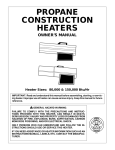
FIGURE E.1 – V160-S BLOCK LOGIC DIAGRAM
S1
115/230/1/50/60
Vac
WHITE 2
1 BLUE
BLACK 4
3 BROWN
RED
AC1
DC+
DC+
DC-
DC-A
AC2
INVERTER BOARD
W05X0190
(SCHEMATIC X0190)
Return to Master TOC
Y/G
GREEN
GND
INPUT BOARD
W05X0250
GND
JP1
(SCHEMATIC X0203)
FAN
1 2 3 4 5 6 7 8 9 10
1
2
JP2
3
6
JP1
DCW1
1 2 3 4 5 6 7 8 9 10 11 12 13 14 15 16
26 25 24 23 22 21 20 19 18 17 16 15 14 13 12 11
DISPLAY BOARD
W05X0245
10 9 8 7 6 5 4 3 2 1
J1
Return to Master TOC
(SCHEMATIC X0245)
WELD CONTROLLER
W05X0233
(SCHEMATIC X0233)
JP1
1
WARNING HIGH VOLTAGE CAN KILL
• Do not operate with coers removed.
• Disconnect input power by unplugging
power cord before servicing.
• Do not touch electrically live parts.
• Only qualified persons should install,
use or service this machine
W1
+
W2
-
BLACK
2
D
3
4
E
5
6
7
8
C
B
A
REMOTE
CONNECTOR
CW
V160-S & -T
THEORY OF OPERATION
Return to Master TOC
Return to Section TOC
E-2
E-2
FIGURE E.2 – GENERAL DESCRIPTION
S1
115/230/1/50/60
Vac
WHITE 2
1 BLUE
BLACK 4
3 BROWN
RED
AC1
DC+
DC+
W1
+
W2
-
BLACK
DC-
DC-A
AC2
INVERTER BOARD
W05X0190
(SCHEMATIC X0190)
Y/G
GREEN
GND
INPUT BOARD
W05X0250
GND
JP1
(SCHEMATIC X0203)
1 2 3 4 5 6 7 8 9 10
1
2
FAN
JP2
3
6
JP1
W1
DC-
1 2 3 4 5 6 7 8 9 10 11 12 13 14 15 16
26 25 24 23 22 21 20 19 18 17 16 15 14 13 12 11
DISPLAY BOARD
W05X0245
10 9 8 7 6 5 4 3 2 1
J1
Return to Master TOC
Return to Master TOC
Return to Master TOC
Return to Section TOC
Return to Section TOC
Return to Section TOC
(SCHEMATIC X0245)
WELD CONTROLLER
W05X0233
(SCHEMATIC X0233)
JP1
1
WARNING HIGH VOLTAGE CAN KILL
• Do not operate with coers removed.
• Disconnect input power by unplugging
power cord before servicing.
• Do not touch electrically live parts.
• Only qualified persons should install,
use or service this machine
2
D
3
4
E
5
6
7
8
C
B
A
REMOTE
CONNECTOR
CW
GENERAL DESCRIPTION
WELDING CAPABILITY
The V160-S is an industrial 160 amp arc welding
power source which utilizes single phase input power,
to produce constant current output. The welding
response of this Invertec has been optimized for stick
(SMAW) and Touch Start TIG (GTAW). The unit is ideal
for industrial applications were portability is important.
The Invertec V-160-S is rated at 160 amps, 26.4 volts,
at 35% duty cycle on a ten minute basis. It is capable
of higher duty cycles at lower output currents. It is
capable of 130 amps, 25.2 volts at a 100% duty cycle.
If the duty cycle is exceeded, a thermal protector will
shut off the output until the machine cools. See
Technical Specifications in A-2 for other related outputs.
The Invertec V160-S is recommended for stick welding
with such popular electrodes as Fleetweld 35,
Fleetweld 37, Fleetweld 180 and LH 78. It features
adjustable arc control to adjust the arc force and start.
The Invertec V160-S performs DC Touch Start Tig
Starting with excellent results.
LIMITATIONS
The V160-S is not recommended for pipe thawing.
NOTE: Unshaded areas of Block Logic
Diagram are the subject of discussion
V160-S & -T
THEORY OF OPERATION
Return to Master TOC
Return to Section TOC
E-3
E-3
FIGURE E.3 – INPUT BOARD
S1
115/230/1/50/60
Vac
RED
1 BLUE
WHITE 2
W1
+
W2
-
BLACK
3 BROWN
BLACK 4
DC+
DC+
AC1
DC-
DC-A
AC2
INVERTER BOARD
W05X0190
(SCHEMATIC X0190)
Y/G
GREEN
GND
INPUT BOARD
W05X0250
GND
JP1
(SCHEMATIC X0203)
FAN
1 2 3 4 5 6 7 8 9 10
1
2
JP2
3
6
JP1
W1
DC-
1 2 3 4 5 6 7 8 9 10 11 12 13 14 15 16
Return to Master TOC
Return to Section TOC
26 25 24 23 22 21 20 19 18 17 16 15 14 13 12 11
DISPLAY BOARD
W05X0245
10 9 8 7 6 5 4 3 2 1
J1
(SCHEMATIC X0245)
WELD CONTROLLER
W05X0233
(SCHEMATIC X0233)
JP1
1
WARNING HIGH VOLTAGE CAN KILL
• Do not operate with coers removed.
• Disconnect input power by unplugging
power cord before servicing.
• Do not touch electrically live parts.
• Only qualified persons should install,
use or service this machine
2
D
3
4
E
5
6
7
8
C
B
A
REMOTE
CONNECTOR
CW
INPUT BOARD
rectified by the input on the input rectifier on the
input board and the resultant DC voltage is applied at
inverter Pcb’s.
Return to Master TOC
Return to Section TOC
The input board includes the following circuits:
INPUT LINE VOLTAGE, FAN CIRCUIT, AUXILIARY VOLTAGE AND
PRECHARGE
The Invertec V160-S can be connected to a 115V or
230V single phase input voltage.
This unit can also connect to engine driven generators but it must follow the below conditions:
Return to Master TOC
Return to Section TOC
• Vac peak voltage: below 250V (for 115Vac input)
or 410V (for 230Vac input).
• Vac frequency: in the range of 50 and 60 Hertz.
• RMS voltage of the AC waveform:
V160-S: 115Vac or 230Vac +/- 10%
The initial power is applied to the Invertec V160-S
directly on the input board. A line switch located on
the back of the machine supplies the logic part that
manages machine functions. The voltage is after
During the precharge time the DC input voltage is
applied to the filter capacitors (located on the inverter
Pcb) through a precharge resistances (located on
input board) that limit the charge current. During
precharge time, an automatic system (manages by
reconnect board mounted on the input board) sets
the input board for 115V or 230V working mode (voltage duplicator when 115Vac is applied). After this
time the start relays go closed and they by-pass the
precharge resistances (there are two precharge
relays, RL1B and RL4B). The input voltage is also
applied to an auxiliary voltage circuit, that gives the
necessary low voltages (+15V, -5V and +5V) for the
control / display board and inverter board.
The fan is activated when the power is first supplied
to the machine. It will stay on as long as output is
present. The fan shuts down after 5 minutes when
the output is shut off.
NOTE: Unshaded areas of Block Logic
Diagram are the subject of discussion
V160-S & -T
Return to Master TOC
Return to Section TOC
E-4
FIGURE E.4 – INVERTER BOARD
S1
115/230/1/50/60
Vac
WHITE 2
1 BLUE
BLACK 4
3 BROWN
RED
AC1
DC+
DC+
DC-A
DC-
INVERTER BOARD
W05X0190
(SCHEMATIC X0190)
Y/G
GREEN
GND
GND
INPUT BOARD
W05X0250
JP1
(SCHEMATIC X0203)
1 2 3 4 5 6 7 8 9 10
1
2
JP2
3
6
JP1
DCW1
Return to Master TOC
Return to Section TOC
1 2 3 4 5 6 7 8 9 10 11 12 13 14 15 16
26 25 24 23 22 21 20 19 18 17 16 15 14 13 12 11
DISPLAY BOARD
W05X0245
10 9 8 7 6 5 4 3 2 1
J1
(SCHEMATIC X0245)
WELD CONTROLLER
W05X0233
(SCHEMATIC X0233)
JP1
1
WARNING HIGH VOLTAGE CAN KILL
• Do not operate with coers removed.
• Disconnect input power by unplugging
power cord before servicing.
• Do not touch electrically live parts.
• Only qualified persons should install,
use or service this machine
2
D
3
4
E
5
6
7
8
C
B
A
REMOTE
CONNECTOR
CW
Return to Master TOC
INVERTER BOARD
Return to Section TOC
The inverter board includes the following circuits:
- Inverter circuit: Transforms the DC current at 80KHz
and feeds the main transformer. The current is regulated via Pulse Width Modulation
- Main transformer: It has two functions:
1) gives the correct output voltage for welding
2) Insulates the operator side from the output
line
- Output circuit: The output diodes rectify the output
the current from the main transformer. The choke filters the output current.The shunt provides output
feedback information to the control board.
Return to Master TOC
W1
+
W2
-
BLACK
AC2
FAN
Return to Section TOC
E-4
THEORY OF OPERATION
NOTE: Unshaded areas of Block Logic
Diagram are the subject of discussion
V160-S & -T
THEORY OF OPERATION
Return to Master TOC
Return to Section TOC
E-5
E-5
FIGURE E.5 – CONTROL/DISPLAY BOARD
S1
115/230/1/50/60
Vac
WHITE 2
1 BLUE
BLACK 4
3 BROWN
RED
DC+
AC1
DC+
DC-A
AC2
DC-
INVERTER BOARD
W05X0190
(SCHEMATIC X0190)
Y/G
GREEN
GND
INPUT BOARD
W05X0250
GND
JP1
(SCHEMATIC X0203)
1 2 3 4 5 6 7 8 9 10
1
2
FAN
JP2
3
6
JP1
DCW1
1 2 3 4 5 6 7 8 9 10 11 12 13 14 15 16
Return to Master TOC
Return to Section TOC
26 25 24 23 22 21 20 19 18 17 16 15 14 13 12 11
DISPLAY BOARD
W05X0245
10 9 8 7 6 5 4 3 2 1
J1
(SCHEMATIC X0245)
WELD CONTROLLER
W05X0233
(SCHEMATIC X0233)
JP1
1
WARNING HIGH VOLTAGE CAN KILL
• Do not operate with coers removed.
• Disconnect input power by unplugging
power cord before servicing.
• Do not touch electrically live parts.
• Only qualified persons should install,
use or service this machine
2
D
3
4
E
5
6
7
8
C
B
A
REMOTE
CONNECTOR
CW
Return to Section TOC
Return to Master TOC
Return to Master TOC
DISPLAY BOARD
Return to Section TOC
W1
+
W2
-
BLACK
The display board receives status and analog signals
from the inverter board and various sensors. It is composed of 2 parts:
- Weld controller: Interprets signals, makes decisions
and changes the machine mode and output to satisfy the requirements dictated by the operator.
- Display board: Supports all the potentiometer,
switches and LED
NOTE: Unshaded areas of Block Logic
Diagram are the subject of discussion
V160-S & -T
THEORY OF OPERATION
Return to Section TOC
Return to Master TOC
Return to Section TOC
Return to Master TOC
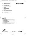
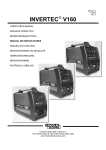
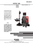
E-6
INSULATED GATE BIPOLAR TRANSISTOR (IGBT) OPERATION
An IGBT is a type of transistor. IGBT are semiconductors well suited for high frequency switching and high
current applications.
Example A in figure E.6 shows an IGBT in passive
mode. There is no gate signal, zero volts relative to the
source, and therefore, no current flow. The drain terminal of the IGBT may be connected to a voltage supply; but since there is no conduction, the circuit will not
supply current to the components connected to the
source. The circuit is turned OFF like a light switch.
POSITIVE
VOLTAGE
APPLIED
Return to Master TOC
Return to Master TOC
n+
Return to Section TOC
Example B shows the IGBT in an active mode. When
the gate signal, a positive DC voltage relative to the
source, is applied to the gate terminal of the IGBT, it is
capable of conducting current. A voltage supply connected to the drain terminal will allow the IGBT to conduct and supply current to the circuit components
coupled to the source. Current will flow through the
conducting IGBT to downstream components as long
as the positive gate signal is present. This is similar to
turning ON a light switch.
FIGURE E.6 - IGBT
SOURCE
Return to Section TOC
E-6
GATE
SOURCE
n+
n+
GATE
n+
p
BODY REGION
p
BODY REGION
n-
DRAIN DRIFT REGION
n-
DRAIN DRIFT REGION
n+
BUFFER LAYER
n+
BUFFER LAYER
p+
INJECTING LAYER
p+
INJECTING LAYER
DRAIN
DRAIN
B. ACTIVE
A. PASSIVE
V160-S & -T
Return to Master TOC
AA-1
TABLE OF CONTENTS - INSTALLATION SECTION V160-T
AA-1
Installation . . . . . . . . . . . . . . . . . . . . . . . . . . . . . . . . . . . . . . . . . . . . . . . . . . . . . . . . . . . . . . . . . . . . . . . . . . .AA-1
Technical Specifications . . . . . . . . . . . . . . . . . . . . . . . . . . . . . . . . . . . . . . . . . . . . . . . . . . . . . . . . . . . . . . .AA-2
Select Suitable Location . . . . . . . . . . . . . . . . . . . . . . . . . . . . . . . . . . . . . . . . . . . . . . . . . . . . . . . . . . . . . .AA-3
Stacking . . . . . . . . . . . . . . . . . . . . . . . . . . . . . . . . . . . . . . . . . . . . . . . . . . . . . . . . . . . . . . . . . . . . . . . . . . .AA-3
Tilting . . . . . . . . . . . . . . . . . . . . . . . . . . . . . . . . . . . . . . . . . . . . . . . . . . . . . . . . . . . . . . . . . . . . . . . . . . . . .AA-3
Return to Master TOC
Machine Grounding and High Frequency Interference Protection . . . . . . . . . . . . . . . . . . . . . . . . . .AA-3/AA-4
Input Connections . . . . . . . . . . . . . . . . . . . . . . . . . . . . . . . . . . . . . . . . . . . . . . . . . . . . . . . . . . . . . . . . . . .AA-4
Ground Connection . . . . . . . . . . . . . . . . . . . . . . . . . . . . . . . . . . . . . . . . . . . . . . . . . . . . . . . . . . . . . .AA-4/AA-5
Output Connections . . . . . . . . . . . . . . . . . . . . . . . . . . . . . . . . . . . . . . . . . . . . . . . . . . . . . . . . . . . . . . . . . .AA-6
Output and Gas Connection for Tig Welding . . . . . . . . . . . . . . . . . . . . . . . . . . . . . . . . . . . . . . . . . . . . . . .AA-6
Work Cable Connection . . . . . . . . . . . . . . . . . . . . . . . . . . . . . . . . . . . . . . . . . . . . . . . . . . . . . . . . . . .AA-6
Output Connection for Stick Welding . . . . . . . . . . . . . . . . . . . . . . . . . . . . . . . . . . . . . . . . . . . . . . . . . . . . .AA-6
Quick Disconnect Plug . . . . . . . . . . . . . . . . . . . . . . . . . . . . . . . . . . . . . . . . . . . . . . . . . . . . . . . . . . . . .AA-7
Return to Master TOC
Return to Master TOC
Shielding Gas Connection . . . . . . . . . . . . . . . . . . . . . . . . . . . . . . . . . . . . . . . . . . . . . . . . . . . . . . . . . .AA-7
Remote Control Connection . . . . . . . . . . . . . . . . . . . . . . . . . . . . . . . . . . . . . . . . . . . . . . . . . . . . . . . . .AA-7
V160-S & -T
INSTALLATION
Return to Master TOC
Return to Section TOC
AA-2
TECHNICAL SPECIFICATIONS - V160-T
INPUT - SINGLE PHASE ONLY
Return to Master TOC
Max. Input Current at rated Output
Input Voltages / 50 /60 Hz.
115 V (20 A Plug and branch)
115 V (30 A branch)
230 V
Output Amps
Duty Cycle
RATED OUTPUT
Output Volts
60 (Stick)
90 (TIG)
100%
Return to Section TOC
AA-2
22.4
13.6
80 (Stick)
110 (TIG)
160 (Stick)
160 (TIG)
35%
Output Current Range
5-160 Amps
Input Circuit
115V (20A Plug and Branch)
23.2
14.4
115V (30A Branch)
25.2
15.2
230V (30A Branch)
230V (30A Branch)
26.4
16.4
130 (Stick)
130 (TIG)
100%
20 A
25 A
34 A
OUTPUT
Maximum Open Circuit Voltage
48 Volts Max.
Type of Output
DC
Return to Section TOC
Return to Master TOC
Return to Section TOC
Return to Master TOC
RECOMMENDED INPUT WIRE AND FUSE SIZES FOR MAXIMUM RATED OUTPUT
INPUT VOLTAGE /
FREQUENCY (HZ)
230/50/60
Height
12.6 in.
320 mm
Width
7.9 in.
200 mm
TYPE S, SO ST, STO, OR EXTRA
HARD USAGE INPUT CORD AWG
#12
PHYSICAL DIMENSIONS
Depth
16.9 in.
430 mm
TEMPERATURE RANGES
MAXIMUM TIME-DELAY CIRCUIT
BREAKER OR FUSE SIZE (AMPS)
30
Weight
Approx. 24.2lbs.
11 kgs.
STORAGE TEMPERATURE RANGE
-50°C to +85°C
OPERATING TEMPERATURE RANGE
-20°C to +40°C
V160-S & -T
INSTALLATION
Return to Master TOC
Return to Section TOC
AA-3
Read entire installation section before starting
installation.
SAFETY PRECAUTIONS
WARNING
ELECTRIC SHOCK can kill.
• Only qualified personnel should perform this installation.
• Disconnect input power by removing
plug from receptacle before working
inside V160-T. Allow machine to sit for
5 minutes minimum to allow the power capacitors
to discharge before working inside this equipment.
Return to Master TOC
Return to Master TOC
Return to Master TOC
Return to Section TOC
Return to Section TOC
Return to Section TOC
• Insulate yourself from the work and ground.
• Always connect the V160-T to a power supply
grounded according to the National Electrical Code
and local codes.
• Always wear dry insulating gloves.
-----------------------------------------------------------SELECT SUITABLE LOCATION
This machine will operate in harsh environments.
However, it is important that simple preventative measures are followed to assure long life and reliable operation.
• Do not place or operate this machine on a surface
with an incline greater than 15° from horizontal.
• This machine must be located where there is free circulation of clean air without restrictions for air movement to and from the air vents. Do not cover the
machine with paper, cloth or rags when switched on.
• Dirt and dust that can be drawn into the machine
should be kept to a minimum.
• Do not mount over combustible surfaces.
AA-3
STACKING
The Invertec V160-T cannot be stacked.
TILTING
Place the machine directly on a secure, level surface.
The machine may topple over if this procedure is not
followed.
MACHINE GROUNDING AND HIGH FREQUENCY INTERFERENCE PROTECTION
The Capacitor Discharge Circuit used in the high frequency generator can be blamed for many radio, TV
and electronic equipment interference problems.
These problems may be the result of radiated interference. Proper grounding methods can reduce or eliminate radiated interference.
The Invertec V160-T has been field tested under recommended installation conditions. It complies with
FCC allowable limits for radiation.
Radiated interference can develop in the following four
ways:
1. Direct interference radiated from the welder.
2. Direct interference radiated from the welding leads.
3. Direct interference radiated from feedback into the
power lines.
4. Interference from re-radiation of “pickup” by
ungrounded metallic objects.
• Keep the machine dry and do not place it on wet
ground or in puddles.
• Locate the machine away from radio controlled
machinery. Normal operation may adversely affect
the operation of nearby radio controlled machinery,
which may result in injury or equipment damage.
Read the section on “Machine Grounding and High
Frequency Interference Protection” in this manual.
• When operated in ambient temperatures greater
than 40°C, the output duty cycle may be reduced.
V160-S & -T
Return to Master TOC
Return to Section TOC
AA-4
INSTALLATION
Keeping these contributing factors in mind, installing
equipment per the following instructions should minimize problems.
1. Keep the welder power supply lines as short as possible and enclose as much of them as possible in
rigid metallic conduit or equivalent shielding for a
distance of 50ft. (15.2m). Both ends of the conduit
should be connected to a driven ground and the
entire length should be continuous.
Return to Master TOC
Return to Section TOC
2. Keep the work and electrode leads as short as possible and as close together as possible. Lengths
should not exceed 25ft. (7.6m). Tape the leads
together when practical.
3. Be sure the torch and work cable rubber coverings
are free of cuts and cracks that allow high frequency leakage. Cables with high natural rubber content,
such as Lincoln Stable-Arc® better resist high frequency leakage than neoprene and other synthetic
rubber insulated cables.
5. The work terminal must be connected to a ground
within ten feet of the welder, using one of the following methods.
Return to Master TOC
Return to Section TOC
b) A 3/4” (19mm) galvanized pipe or a 5/8”
(16mm) solid galvanized iron, steel or copper
rod driven at least eight feet into the ground.
The ground should be securely made and the
grounding cable should be as short as possible
using cable of the same size as the work cable, or
larger. Grounding to the building frame electrical
conduit or a long pipe system can result in re-radiation, effectively making these members radiating
antennas.
6. Keep all panels securely in place.
Return to Master TOC
7. All electrical conductors within 50 ft (15.2m) of the
welder should be enclosed in grounded, rigid metallic conduit or equivalent shielding. Flexible metallic
conduit is generally not suitable.
8. When the welder is enclosed in a metal building,
several earth driven electrical grounds connected
(as in 5 (b) above) around the periphery of the building are recommended.
Failure to observe these recommended installation
procedures can cause radio or TV interference problems.
WARNING
ELECTRIC SHOCK can kill.
• Have a qualified electrician install
and service this equipment.
• Disconnect input power by removing
plug from receptacle before working
inside V160-T. Allow machine to sit
for 5 minutes minimum to allow the
power capacitors to discharge
before working inside this equipment.
• Do not touch electrically hot parts.
-----------------------------------------------------------------------
GROUND CONNECTION
The frame of the welder must be
grounded. A ground terminal marked
with the symbol is located on the under
panel for this purpose. See your local
and national electrical codes for proper
grounding methods.
4. Keep the torch in good repair and all connections
tight to reduce high frequency leakage.
a) A metal underground water pipe in direct contact with the earth for ten feet or more.
Return to Section TOC
INPUT CONNECTIONS
AA-4
CAUTION
The grounding is supplied in the input cord, it is
important that the Supply Receptacle Ground connection is connected.
-----------------------------------------------------------------------
WARNING
This installation should be performed by a qualified electrician to ensure correct connections of
the leads to the plug spades.
• The electrical system must be made by skilled
technicians with the specific professional and
technical qualifications and in compliance with
the regulations in force in the country where the
equipment is installed.
• The welding power source supply cable is provided with a green or yellow/green wire that must
ALWAYS be earthed. This green or yellow/green
wire must NEVER be used with other voltage conductors.
• lnstall only plugs that are corresponding to safety regulations.
------------------------------------------------------------------------
V160-S & -T
Return to Master TOC
Return to Section TOC
AA-5
INSTALLATION
Fuse the input circuit with time delay fuses marked “D”
or delay type1 circuit breakers. Using fuses or circuit
breakers smaller than recommended may result in
“nuisance” shut-offs from welder inrush currents even
if not welding at high currents.
1
Also called “inverse time” or “thermal/magnetic” circuit breakers.
These circuit breakers have a delay in tripping action that decreases
as the magnitude of the current increases.
The Invertec V160-T is recommended for use on an
individual branch circuit.
Return to Master TOC
Return to Section TOC
115V INPUT
The rated output of the V160-T is available when connected to a 30A branch circuit. When connected to a
branch circuit with lower ampacity, lower welding current and duty cycle must be used. An output guide is
provided below. The values are approximate and must
be adjusted downward if the fuse or circuit breaker
trips off. Other loads on the circuit and fuse/circuit
breaker characteristics will affect the available output.
Do not exceed these welding conditions:
15A plug on a 15A branch
10% duty cycle
Stick: 65A
TIG:
95A
Return to Master TOC
Return to Master TOC
Return to Section TOC
Return to Section TOC
When the ARFU has been activated due to an input
over current condition, the output will be turned off and
the green Power LED will blink indicating an over-current condition. This condition usually occurs when the
unit is operated beyond its rated duty cycle. The unit
will self-restore after a short time and will be ready for
normal operation once the green Power LED stops
blinking and remains on.
NOTE: The ARFU replaces a fuse (F2) that was used
in older V160ʼs.
WARNING
• Failure to wire as instructed may cause personal
injury or damage to equipment. To be installed or
checked by an electrician or qualified person
only.
------------------------------------------------------------------------
230V INPUT
To achieve the full output capacity of the V160-T,
230VAC inputs should be used. The change over is
accomplished by replacing the 115VAC plug with a 30
Amp 230VAC plug (NEMA 6-30P).
ATTACHMENT PLUG
In all cases, the green or green/yellow grounding wire
must be connected to the grounding pin of the plug, usually identified by a green screw.
15A plug on a 20A branch
10% duty cycle
Stick: 75A
TIG: 105A
All attachment plugs must comply with the Standard for
Attachment Plugs and Receptacles, UL498.
The product is considered acceptable for use only when
an attachment plug as specified is properly attached to
the supply cord.
20A plug on a 20A branch
10% duty cycle
Stick: 85A
TIG:
120A
The Invertec V160-T is provided with a 115/230V
cable, 6.6ft.(2m) in length, with a 15Amp 5-15P plug
molded onto the cord.
The V160-T is supplied with an additional 20A plug that
can replace the 15A plug to achieve higher output. To
install the supplied 20A plug:
Connect the white (neutral) wire under terminal clamp
with silver screw, and black (hot) wire under terminal
clamp with brass screw. Connect green wire under terminal clamp with green screw.
ARFU (Auto-Restore Fuse)
AA-5
The dual input voltage machine is provided with an
ARFU device. It only operates when the input is connected to an 115V supply and protects from input over
current conditions.
The Invertec V160-T will auto reconnect to either 115V
or 230V supplies.
ENGINE DRIVEN GENERATOR
For use on engine drives, keep in mind the above input
draw restrictions and the following precaution.
The Invertec V160-T can be operated on engine driven
generators as long as the 230 volt auxiliary meets the
following conditions:
• The AC waveform peak voltage is below 400 volts*.
• The AC waveform frequency is between 45 and
65Hz.
• The RMS voltage of the AC waveform is always
greater than 208VAC *.
* for 115 VAC input divide these values in half.
The following Lincoln engine drives meet these conditions when run in the high idle mode:
V160-S & -T
INSTALLATION
Return to Master TOC
Return to Section TOC
AA-6
• Ranger 250,305
• Commander 300, 400, & 500
Many engine drives do not meet these conditions (eg
Miller Bobcats, etc). Operation of the Invertec V160-T
is not recommended on engine drives not conforming
to these conditions. Such combinations may overvoltage the Invertec V160-T power source.
WARNING
OUTPUT CONNECTIONS
Return to Master TOC
Return to Section TOC
ELECTRIC SHOCK can kill.
• Keep the electrode holder, TIG
torch and cables insulation in good
condition and in place.
OUTPUT AND GAS CONNECTION FOR
TIG WELDING (FIGURE AA.1)
FIGURE AA.1
GAS HOSE NOZZLE
TIG TORCH
Return to Master TOC
Return to Section TOC
WORK CABLE
Return to Master TOC
Return to Section TOC
COMPOSÉ DE RETENUE
The ground lead and TIG Torch Twist Mate®
Connector are supplied with the welder. To connect the
cables, turn the PowerSwitch “OFF”. Connect the torch
Twist Mate plug into the DC(-) Electrode/Gas Output
Receptacle on the front of the welder and turn it clockwise until tight.
WORK CABLE CONNECTION
Next, connect the work cable to the “+” output terminal
in the same way.
To minimize high frequency interference, refer to
Machine Grounding and High Frequency
Interference Protection section of this manual for the
proper procedure on grounding the work clamp and
work piece.
• Do not touch electrically live parts or electrode
with skin or wet clothing.
• Insulate yourself from work and ground.
• Turn the input line Switch on the Invertec V160T “off” before connecting or disconnecting output cables or other equipment.
-----------------------------------------------------------
WORK CLAMP
This unit does not include a TIG torch, but one may be
purchased separately. The Lincoln PTA-9 (K1781-1 or
K1781-3 only with no gas valve) or PTA-17 (K1782-1
or K1782-3) are recommended for use with this
machine for this purpose; however, any similar TIG
torch can be used. To attach the Twist-Mate Plug to a
Lincoln Torch, slide the rubber boot onto the torch
cable (enlarge the boot opening if necessary), screw
the fitting on the torch cable into the brass connector
snugly and slide the boot back over the brass connector.
ADAPTEUR DE TIG
AA-6
OUTPUT CONNECTION
WELDING (FIGURE AA.2)
FIGURE AA.2
FOR
STICK
WORK CLAMP
WORK CABLE
ELECTRODE
HOLDER
First determine the proper electrode polarity for the
electrode to be used. Consult the electrode data for
this information. Then connect the output cables to the
output terminals corresponding to this polarity. For
INITIALISATION DE PASSE-FILS
instance, for DC(+) welding, connect the electrode
cable (which is connected to the electrode holder) to
the “+” output terminal and the work cable (which is
connected to the work clamp) to the “-” output terminal.
Insert the connector with the key lining up with the keyLE TIG INCENDIENT LE CABLE ÉLECTRIQUE AVEC LE GAZ FITING
way, and rotate approximately 1/4 turn clockwise; until
the connection is snug. Do not over tighten.
V160-S & -T
INSTALLATION
Return to Master TOC
Return to Section TOC
AA-7
QUICK DISCONNECT PLUG (FOR STICK ELECTRODE CABLE)
A quick disconnect system is used for the welding
cable connections. The stick electrode cable will need
to have a plug attached.
1. Cut off welding cable lug, if present.
2. Remove .75 in. (19mm) of welding cable insulation.
3. Slide rubber boot onto cable end. The boot end
may be trimmed to match the cable diameter. Use
soap or other nonpetroleum-based lubricant to help
slide the boot over the cable, if needed.
SHIELDING GAS CONNECTION
Obtain the necessary inert shielding gas. Connect the
cylinder of gas with a pressure regulator and flow
gage. Install a gas hose between the regulator and gas
inlet (located on the rear of the welder). The gas inlet
has a 5/16-18 right hand female thread; CGA #032.
WARNING
CYLINDER could explode
if damaged.
•Keep cylinder upright
chained to a support.
BOOT
Return to Master TOC
Return to Section TOC
WELDING CABLE
.75 in.
TRIM, IF REQ'D
TO FIT OVER CABLE
4. Cut 45-50% of the copper strands back 1/4” (6
mm).
19 mm
WELDING CABLE
.25 in.
6 mm
5. Fold copper strands over cut strands and insert into
ferrule.
COPPER FERRULE
Return to Master TOC
Return to Section TOC
WELDING CABLE
Return to Master TOC
and
•Keep cylinder away from areas where it could
be damaged.
•Never allow the torch to touch the cylinder.
•Keep cylinder away from live electrical circuits.
___________________________________________
REMOTE CONTROL CONNECTION
A remote control receptacle is provided on the lower
center case front of the welder for connecting a remote
control to the machine. Refer to the Optional
Accessories section of this manual for available
remote controls.
The following items can be connected to the 6 pin
socket on the front panel:
.50 in. max
12 mm max.
6. Slide the copper ferrule into the brass plug.
7. Tighten set screw to collapse copper tube. Screw
must apply pressure against welding cable. The top
of the set screw will be well below the surface of the
brass plug after tightening.
SET SCREW
Return to Section TOC
AA-7
• Remote control potentiometer (K857) for Stick welding.
• Remote Foot Amptrol (K870), Hand Amptrol (K963-3).
• Arc Start Switch (K814).
BRASS PLUG
COPPER TUBE
8. Slide rubber boot over brass plug. The rubber boot
must be positioned to completely cover all electrical
surfaces after the plug is locked into the receptacle.
V160-S & -T
Return to Section TOC
Return to Master TOC
Return to Section TOC
Return to Master TOC
Return to Master TOC
Return to Section TOC
Return to Master TOC
Return to Section TOC
AA-8
NOTES
V160-S & -T
AA-8
Return to Master TOC
BB-1
TABLE OF CONTENTS - OPERATION SECTION
BB-1
Operation . . . . . . . . . . . . . . . . . . . . . . . . . . . . . . . . . . . . . . . . . . . . . . . . . . . . . . . . . . . . . . . . . . . . . . . . . . . .BB-1
Safety Precautions . . . . . . . . . . . . . . . . . . . . . . . . . . . . . . . . . . . . . . . . . . . . . . . . . . . . . . . . . . . . . . . . . . .BB-2
General Description . . . . . . . . . . . . . . . . . . . . . . . . . . . . . . . . . . . . . . . . . . . . . . . . . . . . . . . . . . . . . . . . . .BB-2
Welding Capability . . . . . . . . . . . . . . . . . . . . . . . . . . . . . . . . . . . . . . . . . . . . . . . . . . . . . . . . . . . . . . . . . . .BB-2
Limitations . . . . . . . . . . . . . . . . . . . . . . . . . . . . . . . . . . . . . . . . . . . . . . . . . . . . . . . . . . . . . . . . . . . . . . . . .BB-2
Return to Master TOC
Rear Control Panel . . . . . . . . . . . . . . . . . . . . . . . . . . . . . . . . . . . . . . . . . . . . . . . . . . . . . . . . . . . . . . . . . .BB-3
Controls and Settings, 2 Step and 4 Step Tig Sequence . . . . . . . . . . . . . . . . . . . . . . . . . . . . . . . . .BB-3/BB-6
DIP Switch Functions (Service Information) . . . . . . . . . . . . . . . . . . . . . . . . . . . . . . . . . . . . . . . . . . . . . . .BB-7
DIP Switch 1: Machine Type . . . . . . . . . . . . . . . . . . . . . . . . . . . . . . . . . . . . . . . . . . . . . . . . . . . . . . . .BB-7
DIP Switch 2: Preflow Timer . . . . . . . . . . . . . . . . . . . . . . . . . . . . . . . . . . . . . . . . . . . . . . . . . . . . . . . . .BB-7
DIP Switch 3: 2 Step Restart Enable . . . . . . . . . . . . . . . . . . . . . . . . . . . . . . . . . . . . . . . . . . . . . . . . . .BB-8
DIP Switch 4: 4 Step Restart Enable . . . . . . . . . . . . . . . . . . . . . . . . . . . . . . . . . . . . . . . . . . . .BB-9/BB-10
DIP Switch 5: Low OCV Enable . . . . . . . . . . . . . . . . . . . . . . . . . . . . . . . . . . . . . . . . . . . . . . . . . . . . .BB-11
Return to Master TOC
Return to Master TOC
DIP Switch 6: European/USA Machine Configuration . . . . . . . . . . . . . . . . . . . . . . . . . . . . . . . . . . . .BB-11
DIP Switch 7 & 8: Upslope Timer . . . . . . . . . . . . . . . . . . . . . . . . . . . . . . . . . . . . . . . . . . . . . . . . . . . .BB-12
Start/Crater Current Adjustment . . . . . . . . . . . . . . . . . . . . . . . . . . . . . . . . . . . . . . . . . . . . . . . . . . . . .BB-12
V160-S & -T
OPERATION
Return to Master TOC
Return to Section TOC
BB-2
Read and understand this entire section before
operating your machine.
SAFETY INSTRUCTIONS
WARNING
ELECTRIC SHOCK can kill.
• Do not touch electrically live parts such
as output terminals or internal wiring.
Return to Master TOC
Return to Section TOC
• Insulate yourself from the work and
ground.
• Always wear dry insulating gloves.
____________________________________
FUMES AND GASES
can be dangerous.
• Use ventilation or exhaust to
remove fumes from breathing
zone.
WELDING, CUTTING and
GOUGING SPARKS
can cause fire or explosion
Return to Master TOC
The Invertec V160-T is an industrial 160 amp arc welding power source which utilizes single phase input
power, to produce constant current output. The welding
response of this Invertec has been optimized for stick
(SMAW) and TIG (GTAW). The unit is ideal for industrial applications where portability is important.
The Invertec V160-T performs DC TIG with high frequency or Touch Start Tig Starting with excellent
results.
WELDING CAPABILITY
The Invertec V160-T is rated at 160 amps, 26.4 volts,
at 35% duty cycle on a ten minute basis. It is capable
of higher duty cycles at lower output currents. It is
capable of 130 amps, 25.2 volts at 100% duty cycle(1).
If the duty cycle is exceeded, a thermal protector will
shut off the output until the machine cools. See
Technical Specifications in A-1 for other rated outputs.
The Invertec V160-T is recommended for stick welding
with such popular electrodes as Fleetweld® 35,
Fleetweld 37, Fleetweld 180 and Jet-LH 78 MR.
• Keep your head out of fumes.
____________________________________
Return to Section TOC
GENERAL DESCRIPTION
LIMITATIONS
The V160-T is not recommended for pipe thawing.
(1)When
• Keep flammable material away.
• Do not weld, cut or gouge on
containers that have held combustibles.
____________________________________
ARC RAYS
can burn.
Return to Master TOC
• Wear eye, ear and body
protection.
Return to Section TOC
BB-2
____________________________________
Only qualified personnel should operate this equipment. Observe all safety information throughout this
manual.
V160-S & -T
connected to 230VAC inputs.
Return to Master TOC
Return to Master TOC
Return to Section TOC
Return to Section TOC
BB-3
REAR CONTROL PANEL
OPERATION
1. Power Switch: Controls the input power to the
machine. Make sure the machine is properly connected to the input supply before turning the
machine on.(See Figure BB.1)
2. Fan: The cooling fan will turn ON when the machine
is turned ON and it will continue to run whenever the
output of the machine is ON. If the output of the
machine is OFF for more than five minutes, the fan
will turn OFF. This reduces the amount of dirt that is
deposited inside the machine and reduces power
consumption.(See Figure BB.1)
Refer to the Output LED section below for more information about conditions when the output of the
machine is ON.
3. Gas Inlet: Connector for the TIG shielding gas. The
gas source must have a pressure regulator and flow
gage installed.(See Figure BB.1)
BB-3
• Hot Start: This is a temporary increase in the output
current during the start of the stick welding process.
This helps ignite the arc quickly and reliably.
• Arc Force: This is a temporary increase in the output current during normal stick welding. This temporary increase in output current is used to clear intermittent connections between the electrode and the
weld puddle that occur during normal stick welding.
• Anti-Sticking: This is a function which decreases the
output current of the machine to a low level when
the operator makes an error and sticks the electrode to the work piece. This decrease in current
allows the operator to remove the electrode from the
electrode holder without creating large sparks which
can damage the electrode holder.
CONTROLS AND SETTINGS (See Figure BB.2)
4. Mode Switch: This switch changes the welding
modes of the machine. The V160-T has three welding modes: Stick (SMAW), Lift TIG (GTAW) and HF
TIG (GTAW).
Return to Master TOC
Return to Section TOC
When the mode switch is in the Stick position, the following welding features are enabled:
FIGURE BB.1
1. Power Switch
2. Fan
3. Gas Inlet
1
Return to Master TOC
Return to Section TOC
2
3
V160-S & -T
OPERATION
Return to Master TOC
Return to Master TOC
Return to Master TOC
Return to Section TOC
Return to Section TOC
Return to Section TOC
BB-4
When the mode switch is in the Lift TIG position, the stick
welding functions are disabled and the machine is ready
for Lift TIG welding. Lift TIG is a method of starting a TIG
weld by first pressing the TIG torch electrode on the work
piece in order to create a low current short circuit. Then,
the electrode is lifted from the work piece to start the TIG
arc. After machine output is triggered ON, the arc must be
started within 6.5 seconds or output will turn OFF and trigger sequence must be restarted.
When the mode switch is in the HF TIG position, the stick
welding functions are disabled and the machine is ready
for HF TIG welding. During the HF TIG mode, the TIG arc
is started by HF without pressing the electrode on the
work piece. After triggering output ON, the HF (and output) used for starting the TIG arc will remain ON for 6.5
seconds. If the arc is not started in this time limit, the trigger sequence must be restarted.
5. Trigger Mode Switch: This switch changes between 2step and 4-step trigger sequences. For an explanation of
these trigger sequences refer to the Trigger Mode
Sequences following Controls and Settings.
6. Power LED: This indicator will blink on and off when
the machine is first turned on. After approximately 2
seconds it will stop blinking and remain on to signal that
the machine is ready. The indicator will also blink dur-
ing over current conditions when operating on 115V
input.
7. Thermal LED: This indicator will turn on when the
machine is overheated and the output has been disabled.
This normally occurs when the duty cycle of the machine
has been exceeded. Leave the machine on to allow the
internal components to cool. When the indicator turns off,
normal operation is again possible.
5
4
14
Return to Master TOC
Return to Section TOC
15
16
17
18
19
7
6
FIGURE BB.2
8
9
11
13
10
12
20
BB-4
8. Remote LED: This indicator will turn ON when a
remote control is connected to the machine via the
remote control connector. Using a remote control will
change the function of the output current control., refer
to the output current control section below. (Note:
When K814 Arc Start Switch is connected to remote
connector, remote LED will remain OFF).
9. Output LED: This indicator turns on when the output of
the machine is on.
• In the stick welding mode, the output of the machine is
automatically turned ON.
• For both of the TIG welding modes, the output of the
machine is turned ON and OFF by an Arc Start Switch
or Hand/Foot Amptrol attached to the Remote Control
Connector. (See #4 - Mode Switch - above for details
on output triggering for TIG arc starting).
10. Output Current Control: This controls the output or
welding current of the machine.
The function of this control knob is changed if a remote
control is connected. If the Remote LED is ON, this indicates that a remote control is connected and the function
of the output current control will be:
• Stick Welding Mode: The remote control will adjust the
output current of the machine from 5 to 160A. The
output current control knob on the display panel is not
used.
• TIG Welding Modes: The maximum output current of
the machine is set by the output current control knob.
The remote control then adjusts the output current
from the minimum output (5A) to the value set by the
output current control knob. For example, if the output
current control knob on the machine is set to 100A
then the remote control will adjust the output current
from a minimum of 5A to a maximum of 100A.
11. Downslope Control: In the TIG welding modes, this
control knob will adjust the downslope time from 0.5 to
20 seconds. (The default upslope time is 0.5 seconds.) Refer to the trigger sequence section below to
understand how downslope is activated. In Stick welding mode, this function is not used.
4. Mode Switch
5. Trigger Mode Switch
6. Power LED
7. Thermal LED
8. Remote LED
9. Output LED
10. Output Current Control
11. Downslope Control
12. Postflow Control
13. Digital Display
V160-S & -T
14.
15.
16.
17.
18.
19.
20.
Pulse Mode Switch
Pulse LED
Pulse Frequence Control
Background Current Control
Electrode Connection (Negative)
Remote Control Connector
Electrode Connection (Positive)
Return to Master TOC
Return to Section TOC
BB-5
OPERATION
12. Postflow Control: In the TIG welding modes, this
control knob will adjust the shielding gas postflow time
from 0.5 to 30 seconds. (The preflow time is always
0.5 seconds.) In Stick welding mode, this function is
not used.
13. Digital Display: This meter displays the preset welding current before welding and the actual welding current during welding. Like the output current control,
the function of the meter is changed if a remote control is connected.
Return to Master TOC
Return to Master TOC
Return to Master TOC
Return to Section TOC
Return to Section TOC
Return to Section TOC
14. Pulsing Mode Switch: In the TIG welding modes,
this switch turns the pulsing function ON and controls
the pulsing frequency range (20Hz or 300Hz). In Stick
welding mode, this function is not used.
15. Pulsing LED: This indicator shows the pulsing frequency when pulsing is turned ON. With this indication, the operator can adjust the frequency to the
desired value before welding. (Note: At higher frequencies the LED blinks very fast and seems to be
continuously ON however it is pulsing.) If pulsing is
turned OFF or if the machine is in Stick welding mode,
the indicator will be OFF.
BB-5
After the arc is started the output current will be
increased to the welding current. The time for this
increase or upslope is presettable. The default is 0.5
seconds.
2. Release the Arc Start Switch to stop welding.
The machine will now decrease the output current at
a controlled rate or downslope time, until the
Start/Crater current is reached and the output of the
machine is turned OFF. The downslope time is
adjusted by the Downslope Parameter.
After the arc is turned OFF, the gas valve will remain
open to continue the flow of the shielding gas to the
hot electrode and work piece. The duration of this
postflow shielding gas is adjusted by the Postflow
Parameter. This operation is shown in (2 step diagram 1).
2 Step Diagram 1
16. Pulsing Frequency Control: When the pulsing function is ON, this control knob will adjust the pulsing frequency. The pulsing frequency adjustment range is
0.2 - 20Hz or 3 - 300Hz depending on the Pulsing
Mode Switch position.
17. Background Current Control: When the pulsing
function is ON, this control knob will adjust the pulsing
background current. This is the current during the low
portion of the pulse waveform; it can be adjusted from
10% to 90% of the welding current.
TRIGGER MODE SEQUENCES
For the V160-T, TIG welding can be done in either the 2step or 4-step mode which is selected with the Trigger
Mode Switch. DIP Switch functions are set by the factory.
For adjustments on DIP Switch settings and functions see
DIP SWITCH FUNCTIONS in this Operations Section.
Possible variations of this standard sequence is shown
below. It is possible to press and hold the TIG torch
trigger a second time during downslope to restart. After
the trigger is pressed the output current will increase to
the welding current. This operation is shown in (2 step
diagram 2).
2-Step Sequence
Note: 2-Step works with either an Arc Start Switch (for
output triggering only, current control is at machine) or
with a Foot or Hand Amptrol™ (for both remote output
triggering and current control). 2-Step used with Arc Start
Switch is referenced in following sequence.
1. Press and hold the Arc Start Switch to start the
sequence.
The machine will open the gas valve to start the flow of
the shielding gas. After a 0.5 second preflow time to
purge air from the torch hose, the output of the machine
is turned ON. At this time the arc can be started.
V160-S & -T
2 Step Diagram 2
Return to Master TOC
Return to Master TOC
Return to Section TOC
Return to Section TOC
BB-6
4-Step Sequence
OPERATION
Note: 4-Step works with Arc Start Switch only. Amptrol™
type devices will not work properly and should not
be used. The Arc Start Switch's actuator is also
referred to as the "Tig torch trigger" in the following
sequence.
1. Press and hold the Arc Start Switch to start the
sequence. The machine will open the gas valve to start
the flow of the shielding gas. After 0.5 second preflow
time to purge air from the torch hose, the output of the
machine is turned ON. At this time the arc can be started. After the arc is started the output current will be at
the Start/Finish current. This condition can be maintained as long or as short as necessary.
Possible variations of this standard sequence are
shown below. It is possible to press and hold the TIG
torch trigger another time to end the downslope time
and maintain the output current at the Start/Finish current. When the TIG torch trigger is released the output
will turn OFF and postflow will begin. This operation
shown in (4 step diagram 2).
If the Start/Finish current is not necessary, do not hold
the TIG torch trigger as described at the beginning of
this step. Instead, quickly press and release the trigger.
In this condition, the machine will automatically pass
from Step 1 to Step 2 when the arc is started.
2. Release the TIG torch trigger to start the main part of
the weld.
The output current will increase to the welding current.
The time for this increase or upslope is presettable.
The default is 0.5 seconds.
Return to Section TOC
Return to Master TOC
Return to Master TOC
3. Press and hold the TIG torch trigger when the main part
of the weld is complete.
Return to Section TOC
BB-6
The machine will now decrease the output current at a
controlled rate or downslope time, until the Start/Finish
current is reached. The downslope time is adjusted by
the Downslope Parameter. This Start/Finish current
can be maintained as long or as short as necessary.
4. Release the TIG torch trigger.
The output current of the machine will turn OFF and the
gas valve will remain open to continue the flow of the
shielding gas. The duration of this postflow time is
adjusted by the Postflow control knob. This operation is
shown in (4 step diagram 1).
4 Step Diagram 1
V160-S & -T
4 Step Diagram 2
Return to Master TOC
Return to Master TOC
Return to Master TOC
DIP SWITCH FUNCTIONS
OPERATION
The following sections explain the 8 DIP switch func-
tions of the V160. Read and understand the functions
before making any changes because abnormal operation can occur with the wrong settings. The machine
must be turned OFF when the DIP Switches are
changed.
WARNING
ELECTRIC SHOCK CAN KILL:
Be sure that all installation, operation,
maintenance and repair procedures
are performed only by qualified individuals.
Lincoln Electric is not
responsible for damages caused by improper
installation, improper care or abnormal operation.
DIP Switch 1: Machine Type
DIP Switch 2: Preflow Timer
This controls the preflow timer for TIG welding (used
only on "T" type machines). When the DIP switch is
OFF the preflow time is 0.5 seconds. When it is ON
the preflow time is 0.1 seconds.
FIGURE BB.3
Front of machine
The DIP switches are numbered from 1 to 8 shown in
Figure BB.3. Switch 1 is on the bottom and switch 8 is
on the top. When a switch is pushed to the right (or to
the back of the machine) it is ON; when it is pushed to
the left (or to the front of the machine) it is OFF.
The standard production settings for the V160-T are
shown with in bold letters OFF Table BB.1. If a switch
setting has bold letters OFF, do not make any
changes; abnormal operation could occur.
1
2
3
4
5
6
7
8
OFF
OFF
OFF
ON
OFF
OFF
OFF
OFF
TABLE BB.1
V160-T Pulse
CE
OFF
OFF
OFF
ON
OFF
OFF
OFF
OFF
BB-7
This controls the output of the V160-T and some welding waveform functions. It configures the V160-T to
automatically turn OFF depending on the position of
the Welding Mode switch. Refer to DIP Switch 6 for
more information.
Before opening the machine to make changes to
the DIP Switches it must first be turned OFF and
disconnected from the input source. Do not open
the machine or change the DIP Switches with
power applied to the machine. Only Lincoln
trained service technicians are authorized to perform these modifications.
------------------------------------------------------------------------
DIP
V160-T
Switch
CE
Return to Master TOC
Return to Section TOC
Return to Section TOC
Return to Section TOC
Return to Section TOC
BB-7
DIP
Switch 8
V160-T
USA
OFF
OFF
ON
OFF
OFF
ON
OFF
OFF
DIP
Switch 1
V160-S & -T
Return to Master TOC
Return to Master TOC
Return to Master TOC
Return to Master TOC
Return to Section TOC
Return to Section TOC
Return to Section TOC
Return to Section TOC
BB-8
OPERATION
DIP Switch 3: 2 Step Restart Enable
This controls the 2 Step Restart function. When the
switch is ON the 2 Step Restart function is enabled.
2-Step Restart Disabled (DIP Switch 3 = OFF)
1. Press and hold the TIG torch trigger to start the
sequence. The machine will open the gas valve to
start the flow of the shielding gas. After the preflow
time, the output of the machine is turned ON. At this
time the arc is started according to the selected
welding mode (Lift TIG or HF TIG). After the arc is
started the output current will be increased (upslope) to the welding current.
2-Step Restart Enabled (DIP Switch 3 = ON)
BB-8
Same as step 1.
Same as step 2.
As shown in figure BB.6, it is possible to press and
hold the TIG torch trigger a second time during downslope to restart. After the trigger is pressed the output
current will increase to the welding current, like in step
1. When the main part of the weld is complete go to
the beginning of step 2.
FIGURE BB.6
2. Release the TIG torch trigger to stop welding. The
machine will now decrease the output current at a
controlled rate (downslope), until the Start/Crater
current is reached and the output of the machine is
turned OFF. After the arc is turned OFF, the gas
valve will remain open for the duration of the postflow time.
FIGURE BB.4
As shown in figure BB.5, it is also possible to press and
hold the TIG torch trigger a second time during downslope to end the downslope time and maintain the output current at the Start/Crater current. When the TIG
torch trigger is released the output will turn OFF and
the postflow time will start.
FIGURE BB.5
V160-S & -T
OPERATION
Return to Master TOC
Return to Master TOC
Return to Section TOC
Return to Section TOC
BB-9
DIP Switch 4: 4 Step Restart Enable
This controls the 4 Step Restart function. When the
switch is ON the 4 Step Restart function is enabled.
("Foot pedal" remote controls should never be used
with the 4 step sequences.)
4-Step Restart Disabled (DIP Switch 4 = OFF)
1. Press and hold the TIG torch trigger to start the
sequence. The machine will open the gas valve to
start the flow of the shielding gas. After the preflow
time, the output of the machine is turned ON. At this
time the arc is started according to the selected
welding mode (Lift TIG or HF TIG). After the arc is
started the output current will be at the Start/Crater
current. This condition can be maintained as long or
as short as necessary.
FIGURE BB.7
(1)
Return to Master TOC
Return to Master TOC
Return to Section TOC
(3)
4. Release the TIG torch trigger. The output current of
the machine will turn OFF and the gas valve will
remain open for the duration of the postflow time.
As shown in figure BB.8, after the TIG torch trigger
is quickly pressed and released from step 3A, it is
possible to press and hold the TIG torch trigger
another time to end the downslope time and maintain the output current at the Start/Crater current.
When the TIG torch trigger is released the output
will turn OFF and postflow will begin.
FIGURE BB.8
(3A)
TORCH
BUTTON
––GAS ON––
POST-FLOW
If the Start/Crater current is not necessary, do not hold
the TIG torch trigger as described at the beginning of
this step. Instead, quickly press and release it. In this
condition, the machine will automatically pass from
Step 1 to Step 2 when the arc is started.
(4)
OUTPUT
CURRENT
(4)
––GAS 0N––
GAS
POST-FLOW
Return to Section TOC
(2)
BB-9
POST-FLOW
As shown in figure BB.9, again after the TIG torch
trigger is quickly pressed and released from step
3A, it is possible to quickly press and release the
TIG torch trigger a second time to end the downslope time and stop welding.
FIGURE BB.9
2. Release the TIG torch trigger to start the main part
of the weld. The output current will be increased
(upslope) to the welding current.
3. Press and hold the TIG torch trigger when the main
part of the weld is complete. The machine will now
decrease the output current at a controlled rate
(downslope), until the Start/Crater current is
reached. This Start/Crater current can be maintained as long or as short as necessary.
3A. If it is not necessary to maintain the Start/Crater
current, the TIG torch trigger can be pressed and
released instead of holding it. In this case, step 4
will automatically follow.
V160-S & -T
TORCH
BUTTON
(3A)
OUTPUT
CURRENT
GAS
POST-FLOW
––GAS ON––
OPERATION
Return to Master TOC
Return to Master TOC
Return to Master TOC
Return to Master TOC
Return to Section TOC
Return to Section TOC
Return to Section TOC
Return to Section TOC
BB-10
4-Step Restart Enabled (DIP Switch 4 = ON)
Same as step 1.
TORCH
BUTTON
Same as step 2.
3. Press and hold the TIG torch trigger when the main
part of the weld is complete. The machine will now
decrease the output current at a controlled rate
(downslope), until the Start/Crater current is
reached. This Start/Crater current can be maintained as long or as short as necessary.
FIGURE BB.10
TORCH
BUTTON
(1)
(2)
(3)
(4)
(3A)
OUTPUT
CURRENT
GAS
POST-FLOW
FIGURE BB.11
––GAS ON––
BB-10
(4)
(3A)
OUTPUT
CURRENT
––GAS ON––
GAS
As shown in figure BB.12, again after the TIG torch
trigger is quickly pressed and released from step 3A,
it is possible to quickly press and release the TIG
torch trigger a second time to end the downslope
time and stop welding.
POST-FLOW
This sequence has an automatic restart so welding
will continue after this step. If the weld is completely finished, use the following sequence instead of
step 3 described above.
3A. Quickly press and release the TIG torch trigger.
The machine will now decrease the output current
at a controlled rate (downslope), until the
Start/Crater current is reached and the output of
the machine is turned OFF. After the arc is turned
OFF the postflow time will start.
4. Release the TIG torch trigger. The output current
will again increase (upslope) to the welding current,
like in step 2, to continue welding. When the main
part of the weld is complete go to step 3.
As shown in figure BB.11, after the TIG torch trigger
is quickly pressed and released from step 3A, it is
possible to press and hold the TIG torch trigger
another time to end the downslope time and maintain the output current at the Start/Crater current.
When the TIG torch trigger is released the output
will again increase (upslope) to the welding current,
like in step 4, to continue welding. When the main
part of the weld is complete go to step 3.
V160-S & -T
FIGURE BB.12
TORCH
BUTTON
(3A)
OUTPUT
CURRENT
GAS
POST-FLOW
––GAS ON––
Return to Master TOC
Return to Section TOC
BB-11
DIP Switch 5: Low OCV Enable
This controls the OCV of the machine. When the DIP
switch is OFF the OCV is set to the normal level as
stated in the manuals for the machines. When the
DIP switch is ON the OCV is reduced to 20V. This
low OCV mode was created for the Australian markets and should only be used as required by these
Australian specifications. The low OCV will somewhat
reduce the starting performance of the machine when
dirt, rust, and/or slag is present on the work piece.
Return to Master TOC
DIP Switch 6:
Configuration
Return to Section TOC
OPERATION
• Remote control connected. The TIG slope functions
are disabled for the 2 step trigger mode. If slopes
are needed a foot pedal remote control can be used.
The TIG slope functions are enabled for the 4 step
trigger mode.
A trigger is always needed to turn ON the output of
the machine.
European/USA Machine
This configures several functions of the V160 as
required by the European and USA markets. For the
European market it is OFF and for the USA market it
is ON.
Specifically, this configures the operation of the TIG
slope timers, remote control, and trigger. However,
this configuration also depends on the position of DIP
Switch 1 which selects the machine type. This setting
can be changed but only if the following functions are
clearly understood.
Return to Master TOC
Return to Section TOC
(DIP Switch 1 = OFF)
In TIG welding mode, the following conditions can
exist.
• European Machine Configuration (DIP Switch 6 =
OFF)
The TIG slope functions are always enabled. After
the arc is started the output current will be increased
(upslope) to the welding current. At the end of the
weld the current will be decreased with the downslope function. Using a "foot pedal" remote control is
not recommended with this setup.
A trigger is always needed to turn ON the output of
the machine.
Return to Master TOC
• USA Machine Configuration (DIP Switch 6 = ON)
The TIG slope functions depends on the possible
connection of a remote control.
Return to Section TOC
BB-11
• No remote control connected. The TIG slope functions are enabled. After the arc is started the output
current will be increased (upslope) to the welding
current. At the end of the weld the current will be
decreased with the downslope function.
V160-S & -T
Return to Master TOC
Return to Section TOC
BB-12
DIP Switch 7 & 8: Upslope Timer
OPERATION
These control the upslope timer for TIG welding (used
only on "T" type machines). The following table
shows the DIP Switch settings and selected upslope
time.
DIP Switch 7
ON
OFF
ON
OFF
DIP Switch 8
ON
OFF
OFF
ON
Upslope Time
0.1 seconds
0.5 seconds
1 second
4 seconds
Return to Master TOC
Return to Master TOC
Return to Master TOC
Return to Section TOC
Return to Section TOC
1. Remove the cover of the machine to access the
control Printed Circuit Boards on the case front.
2. To adjust the start/crater current, output current from
the machine must flow through a load bank or a TIG
arc. Connect the necessary equipment. In both
cases, load bank or TIG arc, a trigger must be connected to the machine. If a load bank is used, it must
be setup for 160A and approximately 25V.
3. Make sure all electrical connections are free from
contact with other parts of the machine. Reconnect
the case back if necessary. Turn ON the machine.
Start/Crater Current Adjustment
Return to Section TOC
BB-12
The start/crater current of a "T" type machine can be
changed if necessary. The values are set from the factory.
European Machines:
20% (160A welding current = 32A start/crater current)
USA Machines:
10% (160A welding current = 16A start/crater current)
WARNING
Be sure that all installation, operation, maintenance and repair procedures are performed only
by qualified individuals. Lincoln Electric is not
responsible for damages caused by improper
installation, improper care or abnormal operation.
This adjustment procedure must be performed
only by Lincoln trained service technicians. The
machine will be operating with the cover removed
where it is possible to come in contact with high
voltages. Read all the following instructions
before starting the procedure.
ELECTRIC SHOCK CAN KILL:
• Welding equipment generates high
voltages.
• Do not touch the live parts of the
machine, the electrode, the work
clamp, or connected work pieces
when this equipment is on.
• Insulate yourself from live electrical connections, the electrode, the work clamp, and the
connected work pieces.
-----------------------------------------------------------------------
4. On the control panel of the machine, select the following:
• Mode Switch: LIFT TIG (Do not use HF TIG or damage to measuring equipment will occur.)
• Trigger Mode: 4 Step
• Pulsing: OFF
• Output Current: Maximum (160A)
5. Activate the trigger of the machine to achieve the
start or crater current portion of the welding
sequence. Refer to the trigger sequences explained
above if more information is needed.
6. In this condition, measure the output current of the
machine and adjust the start/crater current as necessary. The calibration trimmer for the start/crater
current is located on the left side of the machine (as
viewed from the front) on the display board. The
access hole for this trimmer is the higher one on the
display board. (Do not adjust the lower trimmer on
the display board; this is the output current calibration.)
The output current is set to 160A, therefore the
start/crater current calibration will be a percentage
of this 160A setting. Use the following equation for
determining the desired start/crater current calibration:
Desired start/crater current percentage multiplied
by 160 = calibration current.
For example, to calibrate the machine for 15%
start/crater current, multiply this by 160 to get the
calibration current ( 0.15 x 160 = 24).
7. Release the trigger to turn off the output of the
machine. Turn OFF the machine and disconnect it
from the input source. Reassemble the machine
making sure the ground wire to the cover is connected.
V160-S & -T
TABLE OF CONTENTS - ACCESSORIES SECTION
Optional Accessories and Compatible Equipment . . . . . . . . . . . . . . . . . . . . . . . . . . . . . . . . . . . . . . . . . .CC-2
Factory, Field Installed . . . . . . . . . . . . . . . . . . . . . . . . . . . . . . . . . . . . . . . . . . . . . . . . . . . . . . . . . . . . . . . .CC-2
Return to Master TOC
Return to Master TOC
CC-1
Accessories . . . . . . . . . . . . . . . . . . . . . . . . . . . . . . . . . . . . . . . . . . . . . . . . . . . . . . . . . . . . . . . . . . . . . . . . . .CC-1
Return to Master TOC
Return to Master TOC
CC-1
V160-S & -T
Return to Master TOC
Return to Section TOC
CC-2
OPTIONAL ACCESSORIES
AND COMPATIBLE EQUIPMENT
ACCESSORIES
CABLE PLUGS
Factory Installed
1-Twist-Mate Torch Connector (W/Gas Pass Through)
1- Ground Lead and Plug Assembly
Strap Packet
Instruction Manual
Return to Section TOC
Return to Master TOC
Return to Section TOC
Return to Master TOC
Field Installed
K870 - Foot Amptroltm for TIG welding. When the
V160-Tʼs Output Control is in the “REMOTE” position,
the foot Amptrol energizes the output and controls the
output remotely. The Foot Amptrol connects directly to
the 6 pin Amphenol.
K963-3 - Hand Amptroltm for TIG welding. When the
V160-Tʼs Output Control is in the “Remote” position,
the hand Amptrol energizes the output and controls the
output remotely. The Hand Amptrol connects directly to
the 6 pin Amphenol.
K852-50 - Cable Plug Kit for 1/0-2/0 cable. Attaches to
welding cable to provide quick disconnect from
machine.
Twist-Mate Torch Adapter K1622-1 - One is shipped
with the welder to connect the Magnum PTA-9 torch. If
you do not care to interchange this part between torches (one is required to connect Magnum PTA-9 or PTA-17
TIG torches with one-piece cable to the V160-T) you
may order an additional adapters. The quick connect
plug provides connection for both gas and welding current.
TIG Torch Parts Kits - Parts kits are available for the
PTA-9 and PTA-17 TIG torches. These kits include
back cap, collets, collect bodies, nozzles and tungsten.
Order KP507 for PTA-9 torches
Order KP508 for PTA-17 torches
See publication E12.150 for parts kits breakdown.
Cut Length Consumables - TIG welding filler metals
are available for welding stainless steel, mild steel, aluminum and copper alloys. See publication C9.10.
K814 - Arc Start Switch - Energizes the output for TIG
welding if remote output control of the amperage is not
desired. It allows on/off TIG welding at the current set
by the Current Control on the control panel. When
using the Arc Start Switch set the Output Control to the
“LOCAL” position.
Magnum® PTA-9 and PTA-17 TIG Torches - The following standard Magnum® TIG torches with one-piece
cable may be used with the Invertec V160-T.
• K1781-1
• K1781-3
• K1782-1
• K1782-3
PTA-9
PTA-9
PTA-17
PTA-17
12.5 ft
25 ft
12.5 ft
25 ft
medium back cap
medium back cap
long back cap
long back cap
Return to Master TOC
NOTE: Each torch requires a Twist-Mate adapter,(one
is included with the machine). Collects, collect
bodies, and nozzles are not included and must
be ordered separately.
Return to Section TOC
CC-2
V160-S & -T
Return to Master TOC
DD-1
TABLE OF CONTENTS - MAINTENANCE SECTION
DD-1
Maintenance . . . . . . . . . . . . . . . . . . . . . . . . . . . . . . . . . . . . . . . . . . . . . . . . . . . . . . . . . . . . . . . . . . . . . . . . . .DD-1
Safety Precautions . . . . . . . . . . . . . . . . . . . . . . . . . . . . . . . . . . . . . . . . . . . . . . . . . . . . . . . . . . . . . . . . . .DD-2
Input Filter Capacitor Discharge Procedure . . . . . . . . . . . . . . . . . . . . . . . . . . . . . . . . . . . . . . . . . . . . . . .DD-2
Routine Maintenance . . . . . . . . . . . . . . . . . . . . . . . . . . . . . . . . . . . . . . . . . . . . . . . . . . . . . . . . . . . . . . . . .DD-2
Return to Master TOC
Return to Master TOC
Return to Master TOC
Major Component Location for V160S/T . . . . . . . . . . . . . . . . . . . . . . . . . . . . . . . . . . . . . . . . . . . . . . . . . .DD-3
V160-S & -T
Return to Master TOC
Return to Section TOC
DD-2
SAFETY PRECAUTIONS
WARNING
MAINTENANCE
ELECTRIC SHOCK can kill.
• Have an electrician install and service this equipment.
• Turn the input power off at the fuse
box, disconnect supply lines and
allow machine to sit for five minutes
minimum to allow the power capacitors to discharge before working
inside this equipment.
• Disconnect the power supply before every operation.
-----------------------------------------------------------------------• Always use gloves in compliance with the safety
standards.
• Do not touch electrically live parts.
Return to Master TOC
Return to Master TOC
Return to Master TOC
Return to Section TOC
Return to Section TOC
----------------------------------------------------------------------
Return to Section TOC
CAUTION
DD-2
INPUT FILTER CAPACITOR
DISCHARGE PROCEDURE
WARNING
The machine has internal capacitors which are
charged to a high voltage during power-on conditions.
This voltage is dangerous and must be discharged
before the machine can be serviced. Discharging is
done automatically by the machine each time the
power is switched off. However, you must allow the
machine to sit for at least 5 minutes to allow time for
the process to take place.
------------------------------------------------------------------------
ROUTINE MAINTENANCE
Prevent metal powder from accumulating near the
Heat Sink fins.
WARNING
•Disconnect the power supply before every operation.
-----------------------------------------------------------------------Carry out the following periodic controls on the power
source:
• Clean the power source inside by means of lowpressure compressed air.
• Check the electric connections and all the connection cables.
V160-S & -T
Return to Section TOC
Return to Master TOC
Return to Section TOC
Return to Master TOC
Return to Section TOC
Return to Master TOC
Return to Section TOC
Return to Master TOC
DD-3
1) Front Assembly
2) Rear Assembly
3) Base/Main Assembly
MAINTENANCE
3
1
V160-S & -T
DD-3
Figure DD.1 - Major Component Locations
2
Return to Section TOC
Return to Master TOC
Return to Section TOC
Return to Master TOC
Return to Master TOC
Return to Section TOC
Return to Master TOC
Return to Section TOC
DD-4
NOTES
V160-S & -T
DD-4
Return to Master TOC
EE-1
TABLE OF CONTENTS-THEORY OF OPERATION SECTION
EE-1
Theory of Operation . . . . . . . . . . . . . . . . . . . . . . . . . . . . . . . . . . . . . . . . . . . . . . . . . . . . . . . . . . . . . . . . . . . . .E-1
General Description . . . . . . . . . . . . . . . . . . . . . . . . . . . . . . . . . . . . . . . . . . . . . . . . . . . . . . . . . . . . . . . . . .EE-2
Welding Capability . . . . . . . . . . . . . . . . . . . . . . . . . . . . . . . . . . . . . . . . . . . . . . . . . . . . . . . . . . . . . . . . . . .EE-2
Limitations . . . . . . . . . . . . . . . . . . . . . . . . . . . . . . . . . . . . . . . . . . . . . . . . . . . . . . . . . . . . . . . . . . . . . . . . .EE-2
Input Board . . . . . . . . . . . . . . . . . . . . . . . . . . . . . . . . . . . . . . . . . . . . . . . . . . . . . . . . . . . . . . . . . . . . . . . .EE-3
Return to Master TOC
Inverter Board . . . . . . . . . . . . . . . . . . . . . . . . . . . . . . . . . . . . . . . . . . . . . . . . . . . . . . . . . . . . . . . . . . . . . .EE-4
Display Board . . . . . . . . . . . . . . . . . . . . . . . . . . . . . . . . . . . . . . . . . . . . . . . . . . . . . . . . . . . . . . . . . . . . . . .EE-5
Insulated Gate Bipolar Transistor (IGBT) Operation . . . . . . . . . . . . . . . . . . . . . . . . . . . . . . . . . . . . . . . . .EE-6
FIGURE E.1 — BLOCK LOGIC DIAGRAM.
S1
115/230/1/50/60
Vac
WHITE 2
1 BLUE
BLACK 4
3 BROWN
RED
AC1
DC+
DC+
W1
+
W2
-
BLACK
DC-
DC-A
AC2
INVERTER BOARD
W05X0190
(SCHEMATIC X0190)
Return to Master TOC
Y/G
GREEN
GND
INPUT BOARD
W05X0250
GND
JP1
(SCHEMATIC X0203)
FAN
1 2 3 4 5 6 7 8 9 10
1
2
JP2
3
6
JP1
DCW1
1 2 3 4 5 6 7 8 9 10 11 12 13 14 15 16
26 25 24 23 22 21 20 19 18 17 16 15 14 13 12 11
DISPLAY BOARD
W05X0245
10 9 8 7 6 5 4 3 2 1
J1
(SCHEMATIC X0245)
METER BOARD
W05X0207
Return to Master TOC
(SCHEMATIC X0207)
WELD CONTROLLER
W05X0233
(SCHEMATIC X0233)
JP1
1
WARNING HIGH VOLTAGE CAN KILL
• Do not operate with coers removed.
• Disconnect input power by unplugging
power cord before servicing.
• Do not touch electrically live parts.
• Only qualified persons should install,
use or service this machine
2
D
3
4
E
5
6
7
8
C
B
A
REMOTE
CONNECTOR
CW
V160-S & -T
THEORY OF OPERATION
Return to Master TOC
Return to Section TOC
EE-2
EE-2
FIGURE EE.2 – GENERAL DESCRIPTION, WELDING CAPABILITY & LIMITATIONS
S1
115/230/1/50/60
Vac
WHITE 2
1 BLUE
BLACK 4
3 BROWN
RED
DC+
AC1
DC+
W1
+
W2
-
BLACK
DC-A
AC2
DC-
INVERTER BOARD
W05X0190
(SCHEMATIC X0190)
Y/G
GREEN
GND
INPUT BOARD
W05X0250
GND
JP1
(SCHEMATIC X0203)
1 2 3 4 5 6 7 8 9 10
1
2
FAN
JP2
3
6
JP1
DCW1
1 2 3 4 5 6 7 8 9 10 11 12 13 14 15 16
26 25 24 23 22 21 20 19 18 17 16 15 14 13 12 11
DISPLAY BOARD
W05X0245
10 9 8 7 6 5 4 3 2 1
J1
Return to Master TOC
Return to Master TOC
Return to Section TOC
Return to Section TOC
(SCHEMATIC X0245)
METER BOARD
W05X0207
(SCHEMATIC X0207)
WELD CONTROLLER
W05X0233
(SCHEMATIC X0233)
JP1
1
WARNING HIGH VOLTAGE CAN KILL
• Do not operate with coers removed.
• Disconnect input power by unplugging
power cord before servicing.
• Do not touch electrically live parts.
• Only qualified persons should install,
use or service this machine
2
3
D
4
E
5
6
7
8
C
B
A
REMOTE
CONNECTOR
CW
GENERAL DESCRIPTION
WELDING CAPABILITY
The V160-T is an industrial 160 amp arc welding power
source which utilizes single phase input power, to produce constant current output. The welding response
of this Invertec has been optimized for stick (SMAW)
and Touch Start TIG (GTAW). The unit is ideal for
industrial applications were portability is important.
The Invertec V-160-T is rated at 160 amps, 26.4 volts,
at 35% duty cycle on a ten minute basis. It is capable
of higher duty cycles at lower output currents. It is
capable of 130 amps, 25.2 volts at a 100% duty cycle.
If the duty cycle is exceeded, a thermal protector will
shut off the output until the machine cools. See
Technical Specifications in AA-2 for other related
outputs.
The Invertec V160-T performs DC TIG with high frequency or Touch Start Tig Starting with excellent
results.
The Invertec V160-T is recommended for stick welding
with such popular electrodes as Fleetweld 35,
Fleetweld 37, Fleetweld 180 and Jet-LH 78 MR. It features adjustable arc control to adjust the arc force and
start.
LIMITATIONS
Return to Master TOC
Return to Section TOC
The V160-S is not recommended for pipe thawing.
NOTE: Unshaded areas of Block Logic
Diagram are the subject of discussion
V160-S & -T
THEORY OF OPERATION
Return to Master TOC
Return to Section TOC
EE-3
EE-3
FIGURE EE.3 – INPUT BOARD
S1
115/230/1/50/60
Vac
WHITE 2
1 BLUE
BLACK 4
3 BROWN
RED
AC1
DC+
AC2
DC-A
DC+
W1
+
W2
-
BLACK
DC-
INVERTER BOARD
W05X0190
(SCHEMATIC X0190)
Y/G
GREEN
GND
INPUT BOARD
W05X0250
GND
JP1
(SCHEMATIC X0203)
FAN
1 2 3 4 5 6 7 8 9 10
1
2
JP2
3
6
JP1
DCW1
1 2 3 4 5 6 7 8 9 10 11 12 13 14 15 16
Return to Master TOC
Return to Section TOC
26 25 24 23 22 21 20 19 18 17 16 15 14 13 12 11
DISPLAY BOARD
W05X0245
10 9 8 7 6 5 4 3 2 1
J1
(SCHEMATIC X0245)
METER BOARD
W05X0207
(SCHEMATIC X0207)
WELD CONTROLLER
W05X0233
(SCHEMATIC X0233)
JP1
1
WARNING HIGH VOLTAGE CAN KILL
• Do not operate with coers removed.
• Disconnect input power by unplugging
power cord before servicing.
• Do not touch electrically live parts.
• Only qualified persons should install,
use or service this machine
2
D
3
4
E
5
6
7
8
C
B
A
REMOTE
CONNECTOR
CW
INPUT BOARD
Return to Master TOC
High Frequency circuit: It generates the high voltage to start the welding arc
INPUT LINE VOLTAGE, FAN CIRCUIT, AUXILIARY VOLTAGE AND
PRECHARGE
The Invertec V160-T can be connected to a 115V or
230V single phase input voltage.
This unit can also connect to engine driven generators but it must follow the below conditions:
Return to Master TOC
Return to Section TOC
Return to Section TOC
The input board includes the following circuits:
• Vac peak voltage: below 250V (for 115Vac input)
or 410V (for 230Vac input).
• Vac frequency: in the range of 50 and 60 Hertz.
• RMS voltage of the AC waveform:
V160-T: 115Vac or 230Vac +/- 10%
The initial power is applied to the Invertec V160-T
directly on the input board. A line switch located on
the back of the machine supplies the logic part that
manages machine functions. The voltage is after rectified by the input on the input rectifier on the input
board and the resultant DC voltage is applied at
inverter Pcb’s.
During the precharge time the DC input voltage is
applied to the filter capacitors (located on the inverter
Pcb) through a precharge resistances (located on
input board) that limit the charge current. During
precharge time, an automatic system (manages by
reconnect board mounted on the input board) sets
the input board for 115V or 230V working mode (voltage duplicator when 115Vac is applied). After this
time the start relays go closed and they by-pass the
precharge resistances (there are two precharge
relays, RL1B and RL4B). The input voltage is also
applied to an auxiliary voltage circuit, that gives the
necessary low voltages (+15V, -5V and +5V) for the
control / display board and inverter board.
The fan is activated when the power is first supplied
to the machine. It will stay on as long as output is
present. The fan shuts down after 5 minutes when
the output is shut off.
NOTE: Unshaded areas of Block Logic
Diagram are the subject of discussion
V160-S & -T
THEORY OF OPERATION
Return to Master TOC
Return to Section TOC
EE-4
EE-4
FIGURE EE.4 – INVERTER BOARD
S1
115/230/1/50/60
Vac
WHITE 2
1 BLUE
BLACK 4
3 BROWN
RED
AC1
DC+
AC2
DC-A
DC+
W1
+
W2
-
BLACK
DC-
INVERTER BOARD
W05X0190
(SCHEMATIC X0190)
Y/G
GREEN
GND
INPUT BOARD
W05X0250
GND
JP1
(SCHEMATIC X0203)
FAN
1 2 3 4 5 6 7 8 9 10
1
2
JP2
3
6
JP1
DCW1
Return to Master TOC
Return to Section TOC
1 2 3 4 5 6 7 8 9 10 11 12 13 14 15 16
26 25 24 23 22 21 20 19 18 17 16 15 14 13 12 11
DISPLAY BOARD
W05X0245
10 9 8 7 6 5 4 3 2 1
J1
(SCHEMATIC X0245)
METER BOARD
W05X0207
(SCHEMATIC X0207)
WELD CONTROLLER
W05X0233
(SCHEMATIC X0233)
JP1
1
WARNING HIGH VOLTAGE CAN KILL
• Do not operate with coers removed.
• Disconnect input power by unplugging
power cord before servicing.
• Do not touch electrically live parts.
• Only qualified persons should install,
use or service this machine
2
D
3
4
E
5
6
7
8
C
B
A
REMOTE
CONNECTOR
CW
Return to Master TOC
Return to Section TOC
INVERTER BOARD
The inverter board includes the following circuits:
- Inverter circuit: Transforms the DC current at 80KHz
and feeds the main transformer. The current is regulated via Pulse Width Modulation
- Main transformer: It has two functions:
1) gives the correct output voltage for welding
2) Insulates the operator side from the output
line
Return to Master TOC
Return to Section TOC
- Output circuit: The output diodes rectify the output
the current from the main transformer. The choke filters the output current.The shunt provides output
feedback information to the control board.
NOTE: Unshaded areas of Block Logic
Diagram are the subject of discussion
V160-S & -T
THEORY OF OPERATION
Return to Master TOC
Return to Section TOC
EE-5
EE-5
FIGURE EE.5 – DISPLAY BOARD
S1
115/230/1/50/60
Vac
WHITE 2
1 BLUE
BLACK 4
3 BROWN
RED
DC+
AC1
DC+
W1
+
W2
-
BLACK
DC-A
AC2
DC-
INVERTER BOARD
W05X0190
(SCHEMATIC X0190)
Y/G
GREEN
GND
INPUT BOARD
W05X0250
GND
JP1
(SCHEMATIC X0203)
FAN
1 2 3 4 5 6 7 8 9 10
1
2
JP2
3
6
JP1
DCW1
1 2 3 4 5 6 7 8 9 10 11 12 13 14 15 16
Return to Master TOC
Return to Section TOC
26 25 24 23 22 21 20 19 18 17 16 15 14 13 12 11
DISPLAY BOARD
W05X0245
10 9 8 7 6 5 4 3 2 1
J1
(SCHEMATIC X0245)
METER BOARD
W05X0207
(SCHEMATIC X0207)
WELD CONTROLLER
W05X0233
(SCHEMATIC X0233)
JP1
1
WARNING HIGH VOLTAGE CAN KILL
• Do not operate with coers removed.
• Disconnect input power by unplugging
power cord before servicing.
• Do not touch electrically live parts.
• Only qualified persons should install,
use or service this machine
2
D
3
4
E
5
6
7
8
C
B
A
REMOTE
CONNECTOR
CW
Return to Master TOC
Return to Section TOC
DISPLAY BOARD
The display board receives status and analog signals
from the inverter board and various sensors. It is composed of 2 parts:
- Weld controller: Interprets signals, makes decisions
and changes the machine mode and output to satisfy the requirements as dictated by the operator.
- Display board: Supports all the potentiometer,
switches and LED
Return to Master TOC
Return to Section TOC
- Meter board: Displays the pre-set and actual output
current
NOTE: Unshaded areas of Block Logic
Diagram are the subject of discussion
V160-S & -T
THEORY OF OPERATION
Return to Master TOC
Return to Section TOC
EE-6
INSULATED GATE BIPOLAR TRANSISTOR (IGBT) OPERATION
An IGBT is a type of transistor. IGBT are semiconductors well suited for high frequency switching and high
current applications.
Example A in figure EE.6 shows an IGBT in passive
mode. There is no gate signal, zero volts relative to the
source, and therefore, no current flow. The drain terminal of the IGBT may be connected to a voltage supply; but since there is no conduction, the circuit will not
supply current to the components connected to the
source. The circuit is turned OFF like a light switch.
EE-6
source, is applied to the gate terminal of the IGBT, it is
capable of conducting current. A voltage supply connected to the drain terminal will allow the IGBT to conduct and supply current to the circuit components
coupled to the source. Current will flow through the
conducting IGBT to downstream components as long
as the positive gate signal is present. This is similar to
turning ON a light switch.
Return to Master TOC
Return to Section TOC
Example B shows the IGBT in an active mode. When
the gate signal, a positive DC voltage relative to the
FIGURE EE.6 - IGBT
POSITIVE
VOLTAGE
APPLIED
SOURCE
Return to Section TOC
Return to Master TOC
Return to Section TOC
Return to Master TOC
n+
GATE
SOURCE
n+
n+
GATE
n+
p
BODY REGION
p
BODY REGION
n-
DRAIN DRIFT REGION
n-
DRAIN DRIFT REGION
n+
BUFFER LAYER
n+
BUFFER LAYER
p+
INJECTING LAYER
p+
INJECTING LAYER
DRAIN
DRAIN
B. ACTIVE
A. PASSIVE
V160-S & -T
Return to Master TOC
F-1
TABLE OF CONTENTS - TROUBLESHOOTING & REPAIR
F-1
Troubleshooting and Repair . . . . . . . . . . . . . . . . . . . . . . . . . . . . . . . . . . . . . . . . . . . . . . . . . . . . . . . . . . . . . .F-1
How to Use Troubleshooting Guide . . . . . . . . . . . . . . . . . . . . . . . . . . . . . . . . . . . . . . . . . . . . . . . . . . . . . . .F-2
PC Board Troubleshooting Procedures and Replacement . . . . . . . . . . . . . . . . . . . . . . . . . . . . . . . . . . . . .F-3
Troubleshooting Guide . . . . . . . . . . . . . . . . . . . . . . . . . . . . . . . . . . . . . . . . . . . . . . . . . . . . . . . . . . . . . . . . .F-4
Case Removal . . . . . . . . . . . . . . . . . . . . . . . . . . . . . . . . . . . . . . . . . . . . . . . . . . . . . . . . . . . . . . . . . . . . . . .F-7
Return to Master TOC
Test Procedures
Input Board Capacitor Discharge Procedure . . . . . . . . . . . . . . . . . . . . . . . . . . . . . . . . . . . . . . . . . . . . .F-9
Input Board Test . . . . . . . . . . . . . . . . . . . . . . . . . . . . . . . . . . . . . . . . . . . . . . . . . . . . . . . . . . . . . . . . .F-11
Main IGBT Inverter Board V160-T “Welding Logic and Inverter” Section Test . . . . . . . . . . . . . . . . . .F-19
Replacement Procedures
Input Board Removal and Replacement Procedure . . . . . . . . . . . . . . . . . . . . . . . . . . . . . . . . . . . . . .F-27
Main IGBT Inverter Board Removal and Replacement Procedure . . . . . . . . . . . . . . . . . . . . . . . . . . .F-31
Display Board Removal and Replacement . . . . . . . . . . . . . . . . . . . . . . . . . . . . . . . . . . . . . . . . . . . . .F-35
Return to Master TOC
Return to Master TOC
Retest After Repair . . . . . . . . . . . . . . . . . . . . . . . . . . . . . . . . . . . . . . . . . . . . . . . . . . . . . . . . . . . . . . . .F-38
V160-S & -T
Return to Master TOC
Return to Section TOC
F-2
TROUBLESHOOTING & REPAIR
HOW TO USE TROUBLESHOOTING GUIDE
WARNING
Service and Repair should only be performed by Lincoln Electric Factory Trained
Personnel. Unauthorized repairs performed on this equipment may result in danger to
the technician and machine operator and will invalidate your factory warranty. For your
safety and to avoid Electrical Shock, please observe all safety notes and precautions
detailed throughout this manual.
---------------------------------------------------------------------------------------------------------------------------
Return to Master TOC
Return to Master TOC
Return to Master TOC
Return to Section TOC
Return to Section TOC
Return to Section TOC
This Troubleshooting Guide is provided to
help you locate and repair possible machine
malfunctions. Simply follow the three-step
procedure listed below.
Step 1. LOCATE PROBLEM (SYMPTOM).
Look under the column labeled “PROBLEM
(SYMPTOMS)”. This column describes possible symptoms that the machine may exhibit. Find the listing that best describes the
symptom that the machine is exhibiting.
Symptoms are grouped into the following
categories: output problems, function problems, wire feeding problems, and welding
problems.
Step 2. PERFORM EXTERNAL TESTS.
The second column labeled “POSSIBLE
AREAS OF MISADJUSTMENT(S)” lists the
obvious external possibilities that may contribute to the machine symptom. Perform
these tests/checks in the order listed. In
general, these tests can be conducted without removing the case wrap-around cover.
Step 3. RECOMMENDED
COURSE OF ACTION
The last column labeled “Recommended
Course of Action” lists the most likely components that may have failed in your
machine. It also specifies the appropriate
test procedure to verify that the subject component is either good or bad. If there are a
number of possible components, check the
components in the order listed to eliminate
one possibility at a time until you locate the
cause of your problem.
All of the referenced test procedures
referred to in the Troubleshooting Guide are
described in detail at the end of this chapter.
Refer to the Troubleshooting and Repair
Table of Contents to locate each specific
Test Procedure. All of the specified test
points, components, terminal strips, etc. can
be found on the referenced electrical wiring
diagrams and schematic. Refer to the
Electrical Diagrams Section Table of
Contents to locate the appropriate diagram.
CAUTION
If for any reason you do not understand the test procedures or are unable to perform the
tests/repairs safely, contact the Lincoln Electric Service Department for technical troubleshooting
assistance before you proceed. Call 1-888-935-3877.
-----------------------------------------------------------------------------------------------------------------------------------
V160-S & -T
F-2
Return to Master TOC
Return to Section TOC
F-3
TROUBLESHOOTING & REPAIR
PC BOARD TROUBLESHOOTING PROCEDURES
WARNING
ELECTRIC SHOCK
can kill.
• Have an electrician install and
service this equipment. Turn the
input power OFF at the fuse box
before working on equipment. Do
not touch electrically hot parts.
Return to Master TOC
Return to Master TOC
Return to Master TOC
Return to Section TOC
Return to Section TOC
Return to Section TOC
CAUTION
Sometimes machine failures appear to be due to PC
board failures. These problems can sometimes be
traced to poor electrical connections. To avoid problems when troubleshooting and replacing PC boards,
please use the following procedure:
1. Determine to the best of your technical ability
that the PC board is the most likely component
causing the failure symptom.
2. Check for loose connections at the PC board
to assure that the PC board is properly
connected.
3. If the problem persists, replace the suspect PC
board using standard practices to avoid static
electrical damage and electrical shock. Read
the warning inside the static resistant bag and
perform the following procedures:
- Remove the PC board from the static-shielding bag
and place it directly into the equipment. Donʼt set the
PC board on or near paper, plastic or cloth which
could have a static charge. If the PC board canʼt be
installed immediately, put it back in the static-shielding bag.
- If the PC board uses protective shorting jumpers,
donʼt remove them until installation is complete.
- If you return a PC board to The Lincoln Electric
Company for credit, it must be in the static-shielding
bag. This will prevent further damage and allow proper failure analysis.
4. Test the machine to determine if the failure
symptom has been corrected by the
replacement PC board.
NOTE: It is desirable to have a spare (known good)
PC board available for PC board troubleshooting.
NOTE: Allow the machine to heat up so that all
electrical components can reach their operating
temperature.
5. Remove the replacement PC board and
substitute it with the original PC board to
recreate the original problem.
a. If the original problem does not reappear by
substituting the original board, then the PC
board was not the problem. Continue to look
for bad connections in the control wiring
harness, junction blocks, and terminal strips.
PC board can be damaged by static electricity.
- Remove your bodyʼs static
charge before opening the staticshielding bag. Wear an anti-static
wrist strap. For safety, use a 1
Meg ohm resistive cord connected
to a grounded part of the
ATTENTION
Static-Sensitive equipment frame.
Devices
- If you donʼt have a wrist strap,
Handle only at touch an un-painted, grounded,
Static-Safe
part of the equipment frame. Keep
Workstations
touching the frame to prevent
static build-up. Be sure not to
touch any electrically live parts at
the same time.
F-3
b. If the original problem is recreated by the
substitution of the original board, then the PC
board was the problem. Reinstall the
replacement PC board and test the machine.
6. Always indicate that this procedure was
followed when warranty reports are to be
submitted.
NOTE: Following this procedure and writing on the
warranty report, “INSTALLED AND SWITCHED PC
BOARDS TO VERIFY PROBLEM,” will help avoid
denial of legitimate PC board warranty claims.
- Tools which come in contact with the PC board must
be either conductive, anti-static or static-dissipative.
V160-S & -T
THEORY OF OPERATION
Return to Master TOC
Return to Master TOC
Return to Master TOC
Return to Master TOC
Return to Section TOC
Return to Section TOC
Return to Section TOC
Return to Section TOC
F-4
Observe Safety Guidelines detailed in the beginning of this manual.
PROBLEMS
(SYMPTOMS)
POSSIBLE AREAS OF
MISADJUSTMENT(S)
GENERAL PROBLEMS
F-4
RECOMMENDED
COURSE OF ACTION
The machine is dead
No LED
No Fan
1. Make sure that the input voltage is present
2. Check the input switch
3. Check the fuse F1, F2, Auto
(depending upon input board
installed
1. Connect correct input voltage
The machine has only the fan running, no display
1. Check the auxiliary voltages on
the JP1 to the input board
1. Perform the Input Board Test
2. Replace if necessary
3. Replace necessary fuse(s) if
they fail again perform the
Input Board Test
2. Replace the display board, if the
auxiliary voltages are present
The machine powers up correctly
but there is no output
1. Check the output LED
2. Check the torch trigger
3. Check the welding cable
CAUTION
1. If the output LED is on perform
the IGBT Inverter Board Test
2. The control board may be faulty
If for any reason you do not understand the test procedures or are unable to perform the tests/repairs safely,
contact the Lincoln Electric Service Department for technical troubleshooting assistance before you proceed.
Call 1-888-935-3877.
V160-S & -T
THEORY OF OPERATION
Return to Master TOC
Return to Master TOC
Return to Section TOC
Return to Section TOC
F-5
Observe Safety Guidelines detailed in the beginning of this manual.
PROBLEMS
(SYMPTOMS)
POSSIBLE AREAS OF
MISADJUSTMENT(S)
GENERAL PROBLEMS
1. Make sure that the tig torch is
good
1. The control board may be faulty
The machine has only touch start
and no HF (V160T pulse only)
1. Check the HF transformer for
loose or faulty connection in HF
area
1. Perform the Input Board Test
The fan does not operate
1. Check if the machine is in
stand-by condition (after 5 minutes of inactivity in tig mode the
fan stops)
1. Replace the fan
The gas solenoid does not work
(V160T only)
2. Check the fan supply voltage,
must be 12vdc
1. Check the gas solenoid supply
voltage, it must be 12vdc, when
the trigger is pressed
Return to Master TOC
Return to Master TOC
2. Perform the Input Board Test
3. The control board may be faulty
1. Perform the Input Board Test
2. The control board may be faulty
2. Replace the gas solenoid
The power LED on the front panel is
“blinking”
1. Check the input voltage
2. Check for high input current due
to exceeding duty cycle rating
1. Check the input voltage, must
match the rating plate
2. Check the mode switch
Return to Section TOC
RECOMMENDED
COURSE OF ACTION
The machine powers up correctly
but working only in stick mode
(V160T pulse)
Bad welding in stick mode
Return to Section TOC
F-5
1. Connect the machine to the correct voltage
2. Perform the Input Board Test
1. Maybe the arc force does not
work, Replace the weld controller board or the display
board
The thermal light remains lit
1. Check the thermal protector on
the output diodes heatsink
1. Perform the Inverter Board Test
The machine has output current but
it is not adjustable
1. Check the current potentiometer
1. Replace the control board
2. Perform the Inverter Board Test
CAUTION
If for any reason you do not understand the test procedures or are unable to perform the tests/repairs safely,
contact the Lincoln Electric Service Department for technical troubleshooting assistance before you proceed.
Call 1-888-935-3877.
V160-S & -T
Return to Section TOC
Return to Master TOC
Return to Section TOC
Return to Master TOC
Return to Master TOC
Return to Section TOC
Return to Master TOC
Return to Section TOC
F-6
NOTES
V160-S & -T
F-6
Return to Master TOC
Return to Section TOC
F-7
TROUBLESHOOTING & REPAIR
CASE COVER REMOVAL AND REPLACEMENT PROCEDURE
WARNING
Service and repair should be performed by only Lincoln Electric factory trained personnel.
Unauthorized repairs performed on this equipment may result in danger to the technician
or machine operator and will invalidate your factory warranty. For your safety and to avoid
electrical shock, please observe all safety notes and precautions detailed throughout this
manual.
Return to Master TOC
Return to Master TOC
Return to Master TOC
Return to Section TOC
Return to Section TOC
Return to Section TOC
If for any reason you do not understand the test procedures or are unable to perform the
test/repairs safely, contact the Lincoln Electric Service Department for electrical troubleshooting assistance before you proceed. Call 1-888-935-3877.
TEST DESCRIPTION
This procedure will aid the technician in the removal and replacement of the case cover.
MATERIALS NEEDED
Phillips Head Screwdriver
V160-S & -T
F-7
TROUBLESHOOTING & REPAIR
Return to Master TOC
Return to Master TOC
Return to Master TOC
Return to Section TOC
Return to Section TOC
Return to Section TOC
F-8
CASE COVER REMOVAL AND REPLACEMENT PROCEDURE (CONTINUED)
FIGURE F.1 – CASE REAR SCREWS - REMOVAL
Four Screws
PROCEDURE
1. Remove input power to the V160S/T
2. Using a phillips head screwdriver, remove the
four screws on the back. See Figure F.1
3. Pull out the rear panel, take off the handle,
then remove the cover.
Return to Master TOC
4. Perform the Input Filter Capacitor
Discharge Procedure detailed in this
section.
Return to Section TOC
F-8
V160-S & -T
Return to Master TOC
Return to Section TOC
F-9
TROUBLESHOOTING & REPAIR
INPUT FILTER CAPACITOR DISCHARGE PROCEDURE
WARNING
Service and repair should be performed by only Lincoln Electric factory trained
personnel. Unauthorized repairs performed on this equipment may result in danger
to the technician or machine operator and will invalidate your factory warranty. For
your safety and to avoid electrical shock, please observe all safety notes and precautions detailed throughout this manual.
Return to Master TOC
Return to Section TOC
If for any reason you do not understand the test procedures or are unable to perform the test / repairs safely, contact the Lincoln Electric Service Department for
electrical troubleshooting assistance before you proceed. Call 1-888-935-3877.
DESCRIPTION
This procedure will drain off any charge stored in the capacitor that is part of the input
board assembly. The procedure MUST be performed, as a safety precaution, before
conducting any test or repair procedure that requires you to touch internal components
of the machine.
MATERIALS NEEDED
Phillips Screwdriver
Insulated Pliers
Insulated Gloves
Return to Section TOC
Return to Master TOC
Return to Section TOC
Return to Master TOC
High Wattage Resistor (25-1000 ohms and 25 watts minimum)
Volt Meter
V160-S & -T
F-9
TROUBLESHOOTING & REPAIR
Return to Master TOC
Return to Section TOC
F-10
INPUT CAPACITOR DISCHARGE PROCEDURE (continued)
ELECTRIC SHOCK can
kill.
• Have an electrician install
and service this equipment.
• Turn the input power off at
the fuse box before working
on equipment.
Return to Master TOC
Return to Section TOC
• Do not touch electrically hot
parts.
• Prior to performing preventative maintenance, perform the following capacitor discharge procedure to
avoid electric shock.
DISCHARGE PROCEDURE
1. Remove the input power to the machine.
2. Using the phillips head screwdriver remove the
screws securing the case wraparound cover.
4. Obtain a high resistance and high wattage resistor
(25-1000 ohms and 25 watts minimum).
This resistor is not with the machine. NEVER USE
A SHORTING STRAP FOR THIS PROCEDURE.
5. Locate the eight capacitor solder pads shown in
Figure F.2.
6. Using electrically insulated gloves and pliers, hold
the body of the resistor with the pliers and connect
the resistor leads across the two capacitor solder
pads. Hold the resistor in place for 15 seconds.
DO NOT TOUCH CAPACITOR SOLDER PADS
WITH YOUR BARE HANDS.
7. Repeat the discharge procedure for the other
capacitor.
8. Check the voltage across the terminals of all capacitors with a DC voltmeter. Voltage should be zero.
If any voltage remains, repeat the capacitor discharge procedure.
3. Be careful not to make contact with the capacitor
solder pads located on the input board. See Figure
F.2.
Return to Section TOC
Return to Master TOC
Return to Master TOC
FIGURE F.2 – LOCATION OF INPUT FILTER CAPACITOR TERMINALS ON THE INPUT BOARD
Return to Section TOC
F-10
INSULATED
PLIERS
INSULATED
GLOVES
V160-S & -T
Return to Master TOC
Return to Section TOC
F-11
TROUBLESHOOTING & REPAIR
INPUT BOARD TEST
V160-S/T
WARNING
Service and repair should be performed by only Lincoln Electric factory trained
personnel. Unauthorized repairs performed on this equipment may result in danger
to the technician or machine operator and will invalidate your factory warranty. For
your safety and to avoid electrical shock, please observe all safety notes and precautions detailed throughout this manual.
Return to Master TOC
Return to Section TOC
If for any reason you do not understand the test procedures or are unable to perform the test / repairs safely, contact the Lincoln Electric Service Department for
electrical troubleshooting assistance before you proceed. Call 1-888-935-3877.
TEST DESCRIPTION
This test will help determine if the Input Board is functioning properly.
Note: There have been some revisions to the input boards. The older boards are identified with line art drawings. The later boards are presented as digital photographs. Perform correct test procedures for suspect boards.
MATERIALS NEEDED
Analog Volt/Ohmmeter
Phillips Head Screwdriver
Return to Section TOC
Return to Master TOC
Return to Section TOC
Return to Master TOC
Wiring Diagram
V160-S & -T
F-11
TROUBLESHOOTING & REPAIR
INPUT BOARD TEST
V160-S/T (continued)
Return to Master TOC
Return to Section TOC
F-12
FIGURE F.3 – INPUT BOARD
Return to Master TOC
Return to Master TOC
Return to Section TOC
Return to Section TOC
Input Board
TEST PROCEDURE
1. Remove
V160S/T
input
power
2. Perform
Case
Procedure.
to
Removal
3. Perform the Input Filter Capacitor
Discharge Procedure detailed
earlier in this section.
Return to Master TOC
4. Locate the Input board.
Figure F.3.
Return to Section TOC
the
See
V160-S & -T
F-12
TROUBLESHOOTING & REPAIR
Return to Master TOC
Return to Section TOC
F-13
INPUT BOARD TEST
V160-S/T (continued)
FIGURE F.4 – INPUT BOARD
Input board checks
Check the
Fuse F1
Return to Master TOC
Return to Section TOC
Check the
start resistor
(20 Ohms)
Return to Section TOC
Return to Master TOC
Return to Section TOC
Return to Master TOC
Check the input
bridge for shorts
or open
TEST PROCEDURE
1. Locate test points. See figure F.4.
2. Check capacitors + input bridge for
open or shorts.
See input board schematic.
3. Check Fuse F1.
4. Check start resistor for 20 ohms.
V160-S & -T
Check
capacitors for
shorts
F-13
TROUBLESHOOTING & REPAIR
F-14
INPUT BOARD TEST
V160-S/T (continued)
Return to Master TOC
Return to Section TOC
F-14
FIGURE F.5 – INPUT BOARD
Voltage check on JP1 input board
CONNECTOR JP1
Return to Master TOC
Return to Master TOC
Return to Master TOC
Return to Section TOC
Return to Section TOC
Return to Section TOC
PIN 15
PIN 1
PIN 16
Refer PIN 11 as ground
Pin 5 = -5Vdc
Pin 7 = +15Vdc
Pin 9 = +5Vdc
PIN 2
TEST PROCEDURE
1. Locate connector JP1. See figure
F.5.
2. Check pin 5 to pin 11 for -5vdc.
3. Check pin 7 to pin 11 for +15vdc.
4. Check pin 9 to pin 11 for +5vdc.
V160-S & -T
Return to Master TOC
Return to Master TOC
Return to Master TOC
Return to Master TOC
Return to Section TOC
Return to Section TOC
Return to Section TOC
Return to Section TOC
F-15
TROUBLESHOOTING & REPAIR
INPUT BOARD TEST
V160-S/T (continued)
FIGURE F.6 – INPUT BOARD
320 Vdc
DC- DC+
TEST PROCEDURE
1. Locate test points. See Figure F.6.
2. Check AC1 + AC2 for 115 VAC or
230 VAC depending on input
voltage.
3. Check DC+ to DC- for 320Vdc.
V160-S & -T
115V or 230Vac
AC1 AC2
F-15
TROUBLESHOOTING & REPAIR
F-16
INPUT BOARD TEST V160-S/T (continued)
Return to Master TOC
Return to Section TOC
F-16
FIGURE F.6A – INPUT BOARD
CONNECTOR JP1
F2 0 Ohms
Check Capacitors
For Shorts
F1 Fuse
PIN 15
PIN 1
PIN 16
Return to Master TOC
Return to Section TOC
PIN 2
Start Resistor
20 Ohms
TEST PROCEDURE:
D11 Rectifier
115VDC
AC
+
AC
D20 Rectifier
16VDC
1.
2.
3.
4.
-
-
AC
AC
+
Return to Section TOC
Return to Master TOC
Return to Section TOC
Return to Master TOC
INPUT PCB BACKSIDE
TEST PROCEDURE (NEW MODELS)
1. Locate connector JP1. See Figure F.6A.
See Figure F.7. See Figure F.8.
2. Check pin 5 to pin 11 for -5vdc.
3. Check pin 7 to pin 11 for 15vdc.
4. Check pin 9 to pin 11 for +5vdc.
V160-S & -T
Locate Connector JP1. See figure F5.
Check pin 5 to pin 11 for -5Vdc.
Check pin 7 to pin 11 for +15Vdc.
Check pin 9 to pin 11 for +5Vdc.
TROUBLESHOOTING & REPAIR
Return to Master TOC
Return to Section TOC
F-17
INPUT BOARD TEST V160-S/T (continued)
FIGURE F.7 – INPUT BOARD
V160 INPUT PCB INSIDE
F1 Fuse Protects
Reconnect Transformer
Revision Number
F2 Thermostat
-5 VDC Supply
Return to Master TOC
Return to Section TOC
+5 VDC Supply
+15 VDC Supply
Start Resistor
Reconnect Relay
Start Relay
D11 Rectifier
Reconnect PCB
Transformer Relay
Return to Section TOC
Return to Master TOC
Return to Section TOC
Return to Master TOC
T2 Transformer 115 & 230
V160-S & -T
D20 Rectifier
F-17
TROUBLESHOOTING & REPAIR
Return to Master TOC
Return to Section TOC
F-18
F-18
INPUT BOARD TEST V160-S/T (continued)
FIGURE F.8 – INPUT BOARD
V160 TOP VIEW
JP1
115AC or 230AC
Input
Input PCB
F2 Thermostat
320 VDC Input DC-
Return to Master TOC
Return to Master TOC
Return to Master TOC
Return to Section TOC
Return to Section TOC
Return to Section TOC
320 VDC Input DC+
Output Same As
Input
Input 115 or 230
Input Filter PCB
Not On All Models
PWM Drive PCB
Inverter PCB
V160-S & -T
Return to Master TOC
Return to Section TOC
F-19
TROUBLESHOOTING & REPAIR
MAIN IGBT INVERTER BOARD V160-S/T
“WELDING LOGIC AND INVERTER” SECTION TEST
WARNING
Service and repair should be performed by only Lincoln Electric factory trained
personnel. Unauthorized repairs performed on this equipment may result in danger
to the technician or machine operator and will invalidate your factory warranty. For
your safety and to avoid electrical shock, please observe all safety notes and precautions detailed throughout this manual.
Return to Master TOC
Return to Section TOC
If for any reason you do not understand the test procedures or are unable to perform the test / repairs safely, contact the Lincoln Electric Service Department for
electrical troubleshooting assistance before you proceed. Call 1-888-935-3877.
TEST DESCRIPTION
This test will help determine if all of the Welding Logic Circuit and Inverter are functioning
properly.
Note: There have been some revisions to the inverter boards. The older boards are
identified with line art drawings. The later boards are presented as digital photographs. Perform correct test procedures for suspect boards.
MATERIALS NEEDED
Return to Section TOC
Return to Master TOC
Return to Section TOC
Return to Master TOC
Volt/Ohmmeter
Phillips Head Screwdriver
Wiring Diagram
V160-S & -T
F-19
Return to Master TOC
Return to Section TOC
F-20
TROUBLESHOOTING & REPAIR
MAIN IGBT INVERTER BOARD V160-S/T
“WELDING LOGIC AND INVERTER” SECTION TEST (continued)
TEST PROCEDURE
1. Remove input power to the V160S/T
machine.
2. Perform
Case
Procedure.
Cover
Removal
Return to Section TOC
Return to Master TOC
Return to Section TOC
Return to Master TOC
3. Perform the Capacitor Discharge
Procedure detailed earlier in this section.
4. Locate the inverter section of the Main
inverter board.
FIGURE F.9 MAIN IGBT INVERTER BOARD LOCATION
Return to Master TOC
Return to Section TOC
Inverter Board
V160-S & -T
F-20
TROUBLESHOOTING & REPAIR
Return to Master TOC
Return to Section TOC
F-21
MAIN IGBT INVERTER BOARD V160-S/T
“WELDING LOGIC AND INVERTER” SECTION TEST (continued)
FIGURE F.10 MAIN IGBT INVERTER BOARD LOCATION
VOLTAGE CHECKS ON JP1 INVERTER BOARD
Return to Master TOC
Return to Master TOC
Return to Master TOC
Return to Section TOC
Return to Section TOC
REFER PIN 2 AS GROUND
PIN 3 = 15 VDC
PIN 7 = 15 VDC = INVERTER OFF
PIN 7 = 0 VDC = INVERTER ON
Return to Section TOC
F-21
PIN 3
PIN 7
PIN 2
V160-S & -T
CHECK FOR 320 VDC
Return to Master TOC
Return to Section TOC
F-22
TROUBLESHOOTING & REPAIR
MAIN IGBT INVERTER BOARD V160-S/T
“WELDING LOGIC AND INVERTER” SECTION TEST (continued)
FIGURE F.11 MAIN IGBT INVERTER BOARD LOCATION
Return to Master TOC
Return to Section TOC
WAVEFORM ON EACH GATE
Return to Master TOC
Return to Master TOC
Return to Section TOC
Return to Section TOC
5us/div
10V/div
Take note that you need an oscilloscope insulated from
the supply line to do this measure
TEST PROCEDURE
1. Locate 6 gate points indicated on Figure
F.11.
2. Connect scope probe, set at 5us/div +
10V/div, and check waveform on each
gate with ground probe to pin 2 in
molex J1.
V160-S & -T
1 3 5 7 9
NUMBERING
GROUND
2 4 6 8 10
F-22
Return to Master TOC
Return to Section TOC
F-23
TROUBLESHOOTING & REPAIR
MAIN IGBT INVERTER BOARD V160-S/T
“WELDING LOGIC AND INVERTER” SECTION TEST (continued)
F-23
FIGURE F.12 MAIN IGBT INVERTER BOARD LOCATION
CHECK THE IGBT S FOR SHORTS
(AN OPEN STATUS NORMALLY IS EVIDENT)
Return to Master TOC
Return to Section TOC
CHECK FOR THERMAL
PROTECTION (~ 36 OHMS)
CHECK THE OUTPUT
DIODES FOR SHORTS
Return to Master TOC
Return to Section TOC
CHECK FOR (~ 1K OHMS)
CHECK THE DIODES FOR SHORTS
TEST PROCEDURE
1. Locate test points on inverter
board. See Figure F.12.
Return to Master TOC
Return to Section TOC
2. Check IGBT and diodes for shorts.
3. Check thermal protector for ~ 36
ohms.
4. Check lower left section as marked
for ~ 1K Ohms.
V160-S & -T
Return to Master TOC
Return to Master TOC
Return to Section TOC
Return to Section TOC
F-24
TROUBLESHOOTING & REPAIR
MAIN IGBT INVERTER BOARD V160-S/T
“WELDING LOGIC AND INVERTER” SECTION TEST (continued)
F-24
FIGURE F.13 MAIN IGBT INVERTER BOARD LOCATION
VOLTAGE CHECKS ON JP1 INVERTER BOARD:
REFER PIN 2 AS GROUND
PIN 3 = 15 VDC
PIN 7 = O VDC (INVERTER ON)
PIN 7 = 15 VDC (INVERTER OFF)
JP1:9 TO JP1:2 C FB (Current feedback from shunt) (Voltage signal between 0-10V = 0-600 Example 100A=1.66V)
JP1:10 to JP1:2 V FB (Voltage feedback) (Voltage signal bewteen 0-10V = 0-60 Example 7.1V = 42v)
R17 PTC
36 Ohms
PIN 3
REVISION NUMBER
PIN 7
D11 CHECK FOR SHORT
PIN 2
2
1
Return to Master TOC
Return to Section TOC
1
OUTPUT DIODES
1K BOTH WAYS
CAN BE CHECKED AT
OUTPUT STUDS
ALSO
1
Return to Master TOC
2
1
1
2
2
1
CHECK
BETWEEN POINTS
1&2
FOR SHORTS
2
D17
CHECK FOR SHORT
27 Ohms
NORMAL
D19
CHECK FOR SHORT
27 Ohms
NORMAL
INVERTER PCB
Return to Section TOC
2
V160-S & -T
Return to Master TOC
Return to Section TOC
F-25
TROUBLESHOOTING & REPAIR
MAIN IGBT INVERTER BOARD V160-S/T
“WELDING LOGIC AND INVERTER” SECTION TEST (continued)
FIGURE F.14 MAIN IGBT INVERTER BOARD LOCATION
Return to Master TOC
Return to Section TOC
GATE DRIVE
OUTPUT
RECTIFIER
IGB T
IGBT
Return to Section TOC
Return to Master TOC
Return to Section TOC
Return to Master TOC
SHUNT
1 Ohm
OUTPUT
TRANSFORMER
T3
INSIDE INVERTER PCB
V160-S & -T
F-25
Return to Section TOC
Return to Master TOC
Return to Section TOC
Return to Master TOC
Return to Master TOC
Return to Section TOC
Return to Master TOC
Return to Section TOC
F-26
NOTES
V160-S & -T
F-26
Return to Master TOC
Return to Section TOC
F-27
TROUBLESHOOTING & REPAIR
INPUT BOARD REMOVAL AND REPLACEMENT PROCEDURE
WARNING
Service and repair should be performed by only Lincoln Electric factory trained
personnel. Unauthorized repairs performed on this equipment may result in danger
to the technician or machine operator and will invalidate your factory warranty. For
your safety and to avoid electrical shock, please observe all safety notes and precautions detailed throughout this manual.
Return to Master TOC
Return to Section TOC
If for any reason you do not understand the test procedures or are unable to perform the tests/repairs safely, contact the Lincoln Electric Service Department for
electrical troubleshooting assistance before you proceed. Call 1-888-935-3877.
DESCRIPTION
This procedure will aid the technician in the removal and replacement of the Input Board.
MATERIALS NEEDED
Analog Volt/Ohmmeter
Phillips Head Screwdriver
7mm Nutdriver
Return to Section TOC
Return to Master TOC
Return to Section TOC
Return to Master TOC
Wiring Diagram
V160-S & -T
F-27
Return to Master TOC
Return to Section TOC
F-28
TROUBLESHOOTING & REPAIR
INPUT BOARD REMOVAL AND REPLACEMENT PROCEDURE
(continued)
FIGURE F.15 – INPUT BOARD
Return to Master TOC
Return to Master TOC
Return to Section TOC
Return to Section TOC
Input Board
REMOVAL PROCEDURE
1. Remove input power to the V160-S/T.
2. Perform the Case Cover Removal
Procedure.
3. Perform the Capacitor Discharge
Procedure.
Return to Master TOC
Return to Section TOC
4. Locate the Input Board. See Figure F.15.
5. Label and remove plugs JP1, JP2, and
JP3. See Figure F.16.
6. Label and remove leads DC-, DC+, AC1,
AC2, and ground. See Figure F.16.
7. Using a 7mm nutdriver remove the four
P.C. Board mounting screws. See Figure
F.16.
8. The Board may now be tilted forward to
gain access to leads HF1 and HF2.
Label and disconnect these leads. See
Figure F.16.
9. Disconnect ground lead. See Figure
F.16.
10. Carefully remove and replace Input
Board.
V160-S & -T
F-28
Return to Master TOC
Return to Master TOC
Return to Master TOC
Return to Section TOC
Return to Section TOC
Return to Section TOC
F-29
JP1
TROUBLESHOOTING & REPAIR
INPUT BOARD REMOVAL AND REPLACEMENT PROCEDURE
(continued)
JP2
JP3
FIGURE F.16 – INPUT BOARD
AC1 AC2
DC- DC+
HF1
HF2
REPLACEMENT PROCEDURE
1. Connect leads HF1 and HF2 to the new
P.C. Board.
2. Replace 7mm P.C. Board mounting
screws.
4. Connect plugs JP1, JP2, JP3 & Ground
lead.
Return to Master TOC
Ground
7mm
Mounting
Bolts
3. Connect leads DC-. DC+, AC1, AC2, and
ground to P.C. Board.
Return to Section TOC
F-29
5. Install case cover.
V160-S & -T
Return to Section TOC
Return to Master TOC
Return to Section TOC
Return to Master TOC
Return to Master TOC
Return to Section TOC
Return to Master TOC
Return to Section TOC
F-30
NOTES
V160-S & -T
F-30
Return to Master TOC
Return to Section TOC
F-31
TROUBLESHOOTING & REPAIR
MAIN IGBT INVERTER BOARD REMOVAL AND REPLACEMENT
PROCEDURE
WARNING
Service and repair should be performed by only Lincoln Electric factory trained
personnel. Unauthorized repairs performed on this equipment may result in danger
to the technician or machine operator and will invalidate your factory warranty. For
your safety and to avoid electrical shock, please observe all safety notes and precautions detailed throughout this manual.
Return to Master TOC
Return to Section TOC
If for any reason you do not understand the test procedures or are unable to perform the test / repairs safely, contact the Lincoln Electric Service Department for
electrical troubleshooting assistance before you proceed. Call 1-888-935-3877.
DESCRIPTION
This procedure will aid the technician in the removal and replacement of the Main IGBT
Inverter Board.
MATERIALS NEEDED
Volt/Ohmmeter
Phillips Head Screwdriver
7mm Nutdriver
Return to Section TOC
Return to Master TOC
Return to Section TOC
Return to Master TOC
10mm Nutdriver
Wiring Diagram
Oscilloscope
V160-S & -T
F-31
Return to Master TOC
Return to Section TOC
F-32
TROUBLESHOOTING & REPAIR
MAIN IGBT INVERTER BOARD REMOVAL AND REPLACEMENT
PROCEDURE (continued)
REMOVAL PROCEDURE
7. Using a 10mm nutdriver remove the two
bolts connecting the P.C. Board to heavy
leads. See Figure F.19.
1. Remove input power to the V160-S/T.
2. Perform the Case Cover Removal
Procedure.
8. The Board may now be tilted forward to
gain access to the ground lead.
Return to Section TOC
Return to Master TOC
Return to Section TOC
Return to Master TOC
3. Perform the Capacitor Discharge
Procedure.
4. Locate the Inverter Board. See Figure F.17.
5. Using a 7mm nutdriver remove the four P.C.
Board mounting screws. See Figure F.19.
9. Label ground lead position and disconnect.
10. Remove and replace Main Input P.C.
Board.
6. Label and disconnect leads DC-, DC+ and
plug JP1 from the top of the Inverter Board.
See Figure F.18.
FIGURE F.17 MAIN IGBT INVERTER BOARD LOCATION
Return to Master TOC
Return to Section TOC
Inverter Board
V160-S & -T
F-32
Return to Master TOC
Return to Section TOC
F-33
TROUBLESHOOTING & REPAIR
MAIN IGBT INVERTER BOARD REMOVAL AND REPLACEMENT
PROCEDURE (continued)
REPLACEMENT PROCEDURE
1. Connect ground lead to new P.C. Board
2. Position new P.C. Board in its proper location.
3. Replace 2 10 mm bolts previously removed.
Return to Master TOC
Return to Section TOC
4. Connect leads DC-, DC+ and plugs to there
proper position.
5. Replace the previously removed 7mm P.C.
Board mounting screws.
6. Replace the case cover.
FIGURE F.18 MAIN IGBT INVERTER BOARD PLUG LOCATIONS
DC+
JP1
Return to Master TOC
Return to Section TOC
DC-
Return to Master TOC
Return to Section TOC
Ground
V160-S & -T
F-33
Return to Section TOC
Return to Master TOC
Return to Section TOC
Return to Master TOC
F-34
TROUBLESHOOTING & REPAIR
MAIN IGBT INVERTER BOARD REMOVAL AND REPLACEMENT
PROCEDURE (continued)
FIGURE F.19 MAIN IGBT INVERTER BOARD MOUNTING BOLTS
Return to Section TOC
Return to Master TOC
Return to Section TOC
Return to Master TOC
7MM SCREWS
10MM SCREWS
V160-S & -T
F-34
Return to Master TOC
Return to Section TOC
F-35
TROUBLESHOOTING & REPAIR
DISPLAY BOARD REMOVAL AND REPLACEMENT PROCEDURE
WARNING
Service and repair should be performed by only Lincoln Electric factory trained
personnel. Unauthorized repairs performed on this equipment may result in danger
to the technician or machine operator and will invalidate your factory warranty. For
your safety and to avoid electrical shock, please observe all safety notes and precautions detailed throughout this manual.
Return to Master TOC
Return to Section TOC
If for any reason you do not understand the test procedures or are unable to perform the test / repairs safely, contact the Lincoln Electric Service Department for
electrical troubleshooting assistance before you proceed. Call 1-888-935-3877.
DESCRIPTION
This procedure will aid the technician in the removal and replacement of the display
board.
MATERIALS NEEDED
Analog Volt/Ohmmeter
Phillips Head Screwdriver
7mm Nutdriver
Return to Section TOC
Return to Master TOC
Return to Section TOC
Return to Master TOC
2.5mm Allen Wrench
Wiring Diagram
V160-S & -T
F-35
Return to Section TOC
Return to Master TOC
Return to Section TOC
Return to Master TOC
F-36
TROUBLESHOOTING & REPAIR
DISPLAY BOARD REMOVAL AND REPLACEMENT PROCEDURE
(continued)
FIGURE F.20 – DISPLAY BOARD LOCATION
FOUR
2.5 MM
ALLEN
BOLTS
DISPLAY
BOARD
CONTROL
KNOB
RED
CAP
FOUR 7MM
MOUNTING
SCREWS
REMOVAL PROCEDURE
Return to Master TOC
Return to Section TOC
6MM NUT & WASHER
1. Remove input power to the V160-S/T.
2. Perform the Case Cover Removal
Procedure.
3. Perform the Capacitor Discharge
Procedure.
4. Locate the Display Board. See Figure
F.20.
5. Gently place machine on its side.
Return to Master TOC
Return to Section TOC
6. Using a 7mm nutdriver remove the three
casefront mounting screws located on
the bottom of the machine. See Figure
F.21.
7. Using a 7mm nutdriver remove the two
casefront mounting screws (four total) on
either side of the machine. See Figure
F.20.
8. The casefront may now be gently pulled
forward to gain access to display board
mounting bolts.
9. Using a thin knife blade or small flathead
screwdriver carefully remove the red
caps on the 5 control knobs located on
the front of the machine. See Figure
F.20.
10. Using a 6mm nutdriver remove the nut
and associated washers located
beneath the previously removed red
caps on the control knobs. See Figure
F.20.
11. Remove control knobs.
12. Using a 2.5mm allen wrench remove
the four display board mounting bolts
located at corners of board. Note
washer position for replacement. See
Figure F.20.
13. Disconnect plugs J1 and JP1 from the
display board.
14. Remove and replace display board.
V160-S & -T
F-36
Return to Master TOC
Return to Master TOC
Return to Master TOC
Return to Section TOC
Return to Section TOC
Return to Section TOC
F-37
TROUBLESHOOTING & REPAIR
DISPLAY BOARD REMOVAL AND REPLACEMENT PROCEDURE
(continued)
FIGURE F.21 – BOTTOM OF MACHINE
7 MM CASEFRONT MOUNTING SCREWS
REPLACEMENT PROCEDURE
1. Connect plugs J1 and JP1 to new display board.
2. Replace the four display board mounting
bolts.
3. Replace control knobs.
Return to Master TOC
Return to Section TOC
4. Replace nuts and associated washers
securing control knobs.
6. Replace the 4 mounting screws on either
side of the machine.
7. Replace the three mounting screws on
the bottom of the machine.
8. Replace the case cover.
5. Replace previously removed red caps.
V160-S & -T
F-37
TROUBLESHOOTING & REPAIR
Return to Master TOC
Return to Section TOC
F-38
RETEST AFTER REPAIR
If a failed test indicates that any mechanical part that could affect the machineʼs electrical characteristics must be replaced or if any electrical components are repaired or
replaced, the machine must be retested and meet the following standards.
INPUT - SINGLE PHASE ONLY
Input Voltages / 50 /60 Hz.
Return to Master TOC
Return to Section TOC
115 V (20 A Plug and branch)
115 V (30 A branch)
230 V
Duty Cycle
100%
35%
Return to Section TOC
Return to Master TOC
Return to Master TOC
100%
Return to Section TOC
F-38
Output Current Range
5-160 Amps
Max. Input Current at rated Output
Output Amps
60 (Stick)
90 (TIG)
RATED OUTPUT
Output Volts
22.4
13.6
80 (Stick)
110 (TIG)
160 (Stick)
160 (TIG)
130 (Stick)
130 (TIG)
20 A
25 A
34 A
Input Circuit
115V (20A Plug and Branch)
23.2
14.4
115V (30A Branch)
25.2
15.2
230V (30A Branch)
26.4
16.4
OUTPUT
Maximum Open Circuit Voltage
48 Volts Max.
230V (30A Branch)
Type of Output
DC
To test V160T on TIG mode set mode switch to LIFT TIG! “do not use HF TIG or damage to measuring equipment will occur!!
To test HF on V160T attach tig torch, remote amptrol, and argon shielding gas.
V160-S & -T
Return to Master TOC
G-1
TABLE OF CONTENTS - DIAGRAM SECTION
G-1
Electrical Diagrams . . . . . . . . . . . . . . . . . . . . . . . . . . . . . . . . . . . . . . . . . . . . . . . . . . . . . . . . . . . . . . . . . . . . .G-1
Wiring Diagram - V160-S (Code 10877) . . . . . . . . . . . . . . . . . . . . . . . . . . . . . . . . . . . . . . . . . . . . . . . . . . .G-2
Wiring Diagram - V160-S (Code 11031) . . . . . . . . . . . . . . . . . . . . . . . . . . . . . . . . . . . . . . . . . . . . . . . . . . .G-3
Wiring Diagram - V160-T (Code 10878) . . . . . . . . . . . . . . . . . . . . . . . . . . . . . . . . . . . . . . . . . . . . . . . . . . .G-4
Wiring Diagram - V160-T (Code 11032) . . . . . . . . . . . . . . . . . . . . . . . . . . . . . . . . . . . . . . . . . . . . . . . . . . .G-5
Schematic - V160-S / -T Page 2 . . . . . . . . . . . . . . . . . . . . . . . . . . . . . . . . . . . . . . . . . . . . . . . . . . . . . . . . .G-7
Schematic - V160-S / -T Input PC Board . . . . . . . . . . . . . . . . . . . . . . . . . . . . . . . . . . . . . . . . . . . . . . . . . .G-8
Schematic - V160-S / -T Input PC Board Voltage Supplies . . . . . . . . . . . . . . . . . . . . . . . . . . . . . . . . . . . .G-9
* NOTE:
Many PC Board Assemblies are now totally encapsulated, surface mounted and or multi-layered
and are therefore considered to be unserviceable. Assembly drawings of these boards are no
longer provided.
Return to Master TOC
Return to Master TOC
Return to Master TOC
Schematic - V160-S / -T Page 1 . . . . . . . . . . . . . . . . . . . . . . . . . . . . . . . . . . . . . . . . . . . . . . . . . . . . . . . . .G-6
V160-S & -T
Return to Master TOC
Return to Section TOC
G-2
WIRING DIAGRAM - V160-S (CODE 10877)
V160-S WIRING DIAGRAM
S1
WHITE 2
115/230/1/50/60
Vac
4
BLACK
1 BLUE
AC1
3
DC+
DC-A
AC2
RED
BLACK
GREEN
Return to Master TOC
DC+
W1
+
DC-
W2
-
BROWN
INVERTER BOARD
W05X0190
INPUT BOARD
Return to Section TOC
G-2
ELECTRICAL DIAGRAMS
GND W05X0250
(SCHEMATIC: X0203)
OR
GREEN /YELLOW
(SCHEMATIC: X0190)
Y/G
GND
1
FAN
JP1
2
1 2 3 4 5 6 7 8 9 10
JP2
3
JP1
4
26 25 24 23 22 21 20 19 18 17 16 15 14 13 12 11
DISPLAY BOARD
W05X0245
(SCHEMATIC: X0245)
J1
WELD CONTROLLER
W05X0233
(SCHEMATIC: X0233)
WARNING: HIGH VOLTAGE CAN KILL
* Do not operate with covers removed.
* Disconnect input power by unplugging
power cord before servicing.
* Do not touch electrically live parts.
* Only qualified persons should install,
use or service this machine.
10 9 8 7 6 5 4 3 2 1
JP1
1 2 3 4 5 6 7 8
D
E
C B A
REMOTE
CONNECTOR
CW
X0261
Return to Master TOC
Return to Master TOC
Return to Section TOC
Return to Section TOC
1 2 3 4 5 6 7 8 9 10 11 12 13 14 15 16
NOTE: This diagram is for reference only. It may not be accurate for all machines covered by this manual. The wiring diagram specific to your code is pasted inside one of the enclosure panels of your machine.
V160-S / T
Return to Section TOC
Return to Master TOC
Return to Section TOC
Return to Master TOC
G-3
G-3
ELECTRICAL DIAGRAMS
WIRING DIAGRAM - V160-S (CODE 11031)
NOTE: INPUT FILTER PCB NOT ON ALL MODELS
WARNING: HIGH VOLTAGE CAN KILL
* Do not operate with covers removed.
* Disconnect input power by unplugging
power cord before servicing.
* Do not touch electrically live parts.
* Only qualified persons should install,
use or service this machine.
J1
Y/G
EARTH
REMOTE BOARD
W05X0322
(SCHEMATIC: X0322)
&
W07X0261rev03
Return to Master TOC
Return to Master TOC
Return to Section TOC
Return to Section TOC
NOTE: DISPLAY PCB NOT ON ALL MODELS
RIBBON CABLE
NOTE: REMOTE PCB NOT ON ALL MODELS
NOTE: This diagram is for reference only. It may not be accurate for all machines covered by this manual. The wiring diagram specific to your code is pasted inside one of the enclosure panels of your machine.
V160-S / T
Return to Master TOC
ELECTRICAL DIAGRAMS
G-4
WIRING DIAGRAM - V160-T (CODE 10878)
Return to Master TOC
Return to Master TOC
Return to Master TOC
Return to Section TOC
Return to Section TOC
Return to Section TOC
Return to Section TOC
G-4
NOTE: This diagram is for reference only. It may not be accurate for all machines covered by this manual. The wiring diagram specific to your code is pasted inside one of the enclosure panels of your machine.
V160-S / T
Return to Master TOC
Return to Section TOC
G-5
WIRING DIAGRAM - V160-T (CODE 11032)
V160-T WIRING
DIAGRAM
WHITE
BLUE
2
115/230/1/50/60
Vac
BLACK
1
4
3
BROWN
Return to Master TOC
AC1
DC+
AC2
DC-A
RED
BLACK
DC+
W1
DC-
W2
S1
GREEN
OR
YELLOW / GREEN
Return to Section TOC
G-5
ELECTRICAL DIAGRAMS
GND
-
INVERTER BOARD
W05X0190
INPUT BOARD
W05X0203
Y/G
(SCHEMATIC:
X0203)
(SCHEMATIC:
X0190)
GND
1
JP1
FAN
2
1 2 3 4 5 6 7 8 9 10
JP2
HF1
3
GAS
SOLENOID
T1
HF TRANSFORMER
+
HF2
4
JP1
DISPLAY BOARD
W05X0370
(SCHEMATIC: X0370)
26 25 24 23 22 21 20 19 18 17 16 15 14 13 12 11
J1
METER BOARD
W05X0207
WELD CONTROLLER
W05X0233
(SCHEMATIC:
X0233)
WARNING: HIGH VOLTAGE CAN KILL
* Do not operate with covers removed.
* Disconnect input power by unplugging
power cord before servicing.
* Do not touch electrically live parts.
* Only qualified persons should install,
use or service this machine.
10 9 8 7 6 5 4 3 2 1
(SCHEMATIC:
X0207)
JP1
*
J1
Y/G
*
EARTH
REMOTE BOARD
W05X0322
(SCHEMATIC: X0322)
W07X0262rev03
Return to Master TOC
Return to Master TOC
Return to Section TOC
Return to Section TOC
1 2 3 4 5 6 7 8 9 10 11 12 13 14 15 16
RIBBON CABLE
NOTE: This diagram is for reference only. It may not be accurate for all machines covered by this manual. The wiring diagram specific to your code is pasted inside one of the enclosure panels of your machine.
V160-S / T
Return to Master TOC
Return to Section TOC
G-6
G-6
ELECTRICAL DIAGRAMS
SCHEMATIC - V160-S & -T (PAGE 1)
D-H
DC+a
320V
DC+
HGTP12N0604A
Q8
Q6
C12
1nF
1600V
Q4
R14
10R
3W
D19
STTA1206D
R30
10R
3W
C6
2n2F
630V
D12
D9
R26
10R
R21
10R
R19
10R
C14
10nF
1600V
MONTARE
VOLANTE
C*
10nF
1600V
K-D
110V
D14
V-O
160A
L1
D17
BYT12PI
TA2
110V 100A
T2B
D16
1.5KE250
B
D-L
D10
D11
C8
1nF
1600V
STTA1206DI
HGTP12N0604A
R16
10R
3W
Q3
Q5
R27
220R
1W
C7
2n2F
630V
D13
Q7
D15
R29
1K
5W
R15
4R7
3W
D18
D-H
C9
4n7F
4kV
C13
4n7F
4kV
D
T3
MONTARE
VOLANTE
NON MONTARE R7
T2A
4
R28
6
C**
4 F
400V
R32
3
R7
150K
2W
R31
1
C2
4 F
400V
Return to Master TOC
Return to Section TOC
EH
A
TA1
GH
C
W1
BYV26E
C10
4n7F
4kV
R6
4R7
3W
C11
3n3F
1600V
C15
4n7F
4kV
R22
W2
DCDC-a
R18
10R
R20
10R
1mohm
R25
10R
A1
R1
22K
R23
EL
V_FB
C_FB
OCV
V-O
ISIS+
IS+
IS-
R3
100K
1 GIRO
CALIBR.
I_SET
PTC
IOUT
IOUT
Return to Master TOC
TA
R4
4R7
0.5W
TA2
1N4148
D1
200mA
+
C1
25V
220µF
D-H
7
COMPONENTI MECCANICI CONNESSI
ELETTRICAMENTE
14
R2
2K7
1/4W
12V/50mA
T1D
T1B
REC
12
R8
470R
K-D
PTC
R9
100R
8
R17
PTC
D5
C5
47µF
25V
+
C4
100µF
25V
REC
ERROR
ON/OFF
PWM
+
GH
V_FB
C_FB
ERROR
ON/OFF
I_SET
OCV
D8
1N4749A
R13
470R
+15V
EH
GL
IRFD110
Q1
T1C
HS3
TA
+15V
NON MONTARE C5
1N4148
D-L
HS1
SOFT-START
IRFD110
Q2
D6
PWM
HS2
R11
470R
1/4W
R12
100R
10
1N4148
D2
5
1N4148
D3
3
+15V
T1A
Return to Master TOC
D4
BYV26B
R5
1K
0.5W
1
Return to Section TOC
TA1
1
2
3
4
5
6
7
8
9
10
11
12
13
14
15
16
17
18
19
20
21
22
23
24
25
R24
CALIBR.
CW
GL
Return to Section TOC
GND
D20
1.5KE250
D7
1N4749A
C3
100µF
25V
+
JP1
10
9
8
7
6
5
4
3
2
1
X0190rev02
R10
470R
EL
1N4148
NOTE: This diagram is for reference only. It may not be accurate for all machines covered by this manual.
V160-S / T
Return to Master TOC
Return to Section TOC
G-7
G-7
ELECTRICAL DIAGRAMS
SCHEMATIC - V160-S & -T (PAGE 2)
AC2
AC2
C**
4n7F
115V
25A
C*
4n7F
DC
W7162430
RL1B 1
7
4
W7165610
RL2B
MONTARE VOLANTE
R5
RL1C 2
8
5
20R
10W
RL1D 3
9
6
-
+ C12
1500µF
250V
+ C15
1500µF
250V
R14
15K
3W
+ C19
1500µF
250V
+ C18
1500µF
250V
R23
15K
3W
DC+
400V
30A
DC+a
+
+HS
L2
D6
1000V
35A
AC1
AC1
DC+
W58X0220
L1
W58X0179
DC-a
DCDC-
VCC
A2
A1
D12
1N4148
T2
200V
1.5A
D20
230V
16V
0.3A
8
A1
Return to Master TOC
+
6
A2
0V
W59X0225
F1
AC2
-
+
D11
1000V
1.5A
C27
1500µF
35V
+HS
PRI+5V
+HS
D22
2V4
PRI+5V
3
OUT
Q4
D44H8
C20
25V
220µF
+
R17
R16
18R
6R8
ERR
PRI GND
W47X0206
R19
R20
270K
1/4W
270K
1/4W
Vref
R21
18K
1/4W
+
C21
47 F
25V
+15Vdc
400V
DC
W59X0173
D2
1N4007
220pF
630V
R3
470R
D4
4
C13
630V
100pF
C7
C5
+
1000µF
25V
1000µF
25V
N.M.
T1B
3
+5Vdc
+
N.M.
+5Vdc
0.5A
U3
A
NON MONTARE R11
R1
470R
R8
1/4W
1K
2
TL431
C2
10µF
63V
OSC
CAP+
CAP-
VOUT
5
-5Vdc
C3
100nF
50V
-5Vdc
10mA
C4
10µF
63V
3
+15Vdc
7
2
4
+
1N4148
D7
/HF
JP1
RL3A
A1
21
22
24
R15
220R
3W
20mA
FAN
EV
ERR
/HF
A2
RL3C
DC
12
14
11
600V
W58X0191
L4
W58X0200
L3
D19
BYV26E
D15
BYV26E
U7
TOP223Y
+HS
CTR
D
1
Return to Master TOC
3
S
HF1
+HS
D13
C17
100nF
32V
50V
W4001003
DC-
-5Vdc
C16
R22
1/4W
680K
C22
470nF
630V
RL3B
Return to Section TOC
Q1
W4300510
R2
10K
8
LMC7660
U2
6
VIN
V+
1
REF
DC-
D1
1N4007
C1
10µF
63V
EV
GND
6
C10
220nF
50V
+HS
OUT
2
3
1N4148
5
6
U4B
CNY17-3
+15Vdc
1
IN
2
R11
5
C9
220µF
25V
1
2
3
4
EV-
C
S
+
2
1
C8
R9
1
4
CTR
+HS
U1
W4607805
CNY17-3
U4A
D3
U5
TOP223Y
FAN-
R4
10K
+15Vdc
2.5A
R7
4K99
GND
D
C6
470nF
63V
W3043470
18V
R10 N.M.
R6
1K
GND
3
1.5KE200V
JP2
+
T1C
Q2
9
T1A
W4300510
FAN
W4028200
12
3
R13
220R
3W
D5
C14
100nF
630V
C11
+15Vdc
D8
BYV26C
Return to Master TOC
IN
Q3
D44H8
1A
220R R12
1W
Return to Section TOC
1
RL2A
+
Return to Section TOC
3 115V
RL1A
W7162430
U6
L7805
RL4A
1
2
3
4
5
6
7
8
9
10
11
12
13
14
15
16
17
18
19
20
PRI GND
Vref
VCC
D21
2V4
+HS
11
GND
RL4B 12
14
2
11
-
RL4C 22
24
+
21
1
A1
D9
1N4148
2N6509
D14
150nF
1200Vdc
D10
BYV26E
+15Vdc
+5Vdc
C***
100nF
50V
R18
22R
1/4W
HF2
1
2
3
4
5
6
7
8
9
10
11
12
13
14
15
16
MONTARE VOLANTE
2
NON MONTARE C24 E D18
C23
1 F
63V
C24
1 F
63V
X0203rev01
R24
R25
10K
1/4W
10K
1/4W
D16
D17
600V
160V
5W
160V
5W
C26
C25
D18
160V
5W
6n8F
1KV
33nF
100V
NOTE: This diagram is for reference only. It may not be accurate for all machines covered by this manual.
V160-S / T
Return to Master TOC
Return to Master TOC
Return to Master TOC
Return to Master TOC
Return to Section TOC
Return to Section TOC
Return to Section TOC
Return to Section TOC
G-8
G-8
ELECTRICAL DIAGRAMS
SCHEMATIC - INPUT PC BOARD
320VDC Input
15VDC
PMW Controlled
100KZ to Maintain
Proper supply
+5VDC
-5VDC
HIGH FREQ CIRCUIT ONLY ON TIG VERSION NOT ON STICK VERSION
NOTE: This diagram is for reference only. It may not be accurate for all machines covered by this manual.
V160-S / T
Return to Master TOC
Return to Master TOC
Return to Section TOC
Return to Section TOC
G-9
G-9
ELECTRICAL DIAGRAMS
SCHEMATIC - INPUT PC BOARD VOLTAGE SUPPLIES
0 volts = Fan Off 12VDC = Fan On (Signal From Control PCB)
0 volts = Fan Off
12VDC = Fan On
Supplies
From
Input Board
If F2 Thermostat Opens U8B Opens
Signal Sent to Control Board When using 115V Input
JP1 To Control PCB
Return to Master TOC
Return to Section TOC
12VDC For Fan Pins 1 & 2
Return to Master TOC
Return to Section TOC
Solenoid Circuit present on TIG machines only
NOTE: This diagram is for reference only. It may not be accurate for all machines covered by this manual.
V160-S / T