1
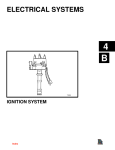
IGNITION SYSTEM
SERVICE MANUAL NUMBER 26
Specifications
Timing
Timing (At Idle rpm)1
1 BTDC2 / 1 ATDC3 / 2 ATDC4
1Timing
must be set using a special procedure as outlined in this section. Timing cannot be properly set using
the conventional method.
2Serial
number break: 0L096999 and below
3Serial
number break: 0L097000 - 0L0340999
4Serial
number break: 0L341000 and above.
Spark Plugs
Spark Plug Gap
.035 In. (0.9 mm)
3.0L
AC-MR43LTS
NGK-BPR6EFS
Champion RS12YC
GM 4-Cylinder In-line Firing
50683
Firing Order 1-3-4-2
Page 4B-4
90-861329--1 MARCH 1999
IGNITION SYSTEM
SERVICE MANUAL NUMBER 26
Description
EST or Electronic Spark Timing is a High Energy Ignition System (HEI). The distributor itself
has no centrifugal advance mechanism or devices.
The spark plug wires are a carbon-impregnated cord conductor with a silicone rubber jacket.
It is important they be handled with care, and routed so as not to cross each other or to be
in contact with other parts of the engine to prevent rubbing.
The EST System uses a square coil with epoxy covered windings to protect against moisture and arc-over.
The timing cannot be set the same way that other ignition systems were.
c
b
e
d
a
f
70106
a
b
c
d
e
f
- Distributor with Spark Plug Wires
- Wires (WHITE) Used in Timing Procedure
- Wire from Shift Interrupt Switch
- Distributor Harness
- Engine Harness Wire (PURPLE AND GRAY)
- Coil
EST uses a magnetic pulse generator and an electronic module to primary circuit current.
Internally the Pulse Generator, or magnetic pick-up assembly, takes the place of conventional points. A timer core on the main shaft of the distributor has external teeth which align
with an equal number of pole piece teeth (four for a four cylinder engine). The electronic
module is small enough to allow it to be mounted inside the distributor, and contains the circuits necessary for dwell control and advance of the timing.
90-861329--1 MARCH 1999
Page 4B-5
IGNITION SYSTEM
SERVICE MANUAL NUMBER 26
Molded into the module is a two-prong connector for the coil terminals and four prong connector. Only three of the four terminals of the second connector are used by MerCruiser (one
for the shift interrupt and two white leads are used to “freeze” advance for properly setting
initial timing). Inside the distributor, the pick-up coil attaches to the module at a molded prong
connector.
a
h
g
e
d
f
c
b
a
b
c
d
e
f
g
h
70107
- Magnetic Pulse Generator
- Electronic Module
- Two Prong Connector
- Four Prong Connector
- Pick-up Coil Connector
- Timer Core
- Pole Piece Teeth
- External Teeth
Precautions
WARNING
When performing the following procedure, be sure to observe the following:
Be sure that engine compartment is well ventilated and that no gasoline vapors
are present, to avoid the possibility of fire.
Be sure to keep hands, feet and clothing clear of moving parts.
Do not touch or disconnect any ignition system parts while engine is running.
Do not reverse battery cable connections. System is negative (–) ground.
Do not disconnect battery cables while engine is running.
Page 4B-6
90-861329--1 MARCH 1999
IGNITION SYSTEM
SERVICE MANUAL NUMBER 26
Cleaning And Inspection
Spark Plugs
1. Inspect each plug individually for badly worn electrodes, glazed, broken or blistered
porcelain and replace plug where necessary.
2. Inspect each spark plug for manufacturer and heat range. All plugs must be the same
manufacturer and number or heat range. Refer to “Specifications” for spark plug numbers.
3. Check spark plug gaps with a round feeler gauge. Adjust if necessary.
e
a
f
b
c
d
50674
Spark Plug Detail
a - Porcelain Insulator
b - Check For Cracks In This Area of Porcelain
c - Shell
d - Proper Gap
e - Side Electrode (Gap Adjustment)
f - Center Electrode (File Flat When Adjusting Gap)
IMPORTANT: Tapered seat spark plugs are not interchangeable with non-tapered
(with gasket) spark plugs.
4. Clean spark plug seating area. DO NOT use gaskets on taper seat plugs. Install spark
plugs and torque to 22 lb-ft (30 Nm). Heat transfer and a gas-tight seal must be achieved.
Spark Plug Wires
1. Inspect spark plug wires for damage.
2. Check spark plug wires for continuity.
3. Replace any wires that are cracked, cut or have damaged spark plug boots.
4. Replace any wires that do not show continuity from end to end.
5. Reinstall spark plug wires in proper order.
IMPORTANT: Proper positioning in spark plug wires is important to prevent cross
firing.
90-861329--1 MARCH 1999
Page 4B-7
IGNITION SYSTEM
SERVICE MANUAL NUMBER 26
Distributor Cap and Rotor
1. Loosen distributor cap retaining screws.
2. Remove distributor cap.
3. Clean cap with warm soap and water and blow off with compressed air.
4. Check cap contact for excessive burning or corrosion. Check center contact for
deterioration.
IMPORTANT: Distributor caps (for marine use) should have brass contacts, aluminum contacts should not be used.
5. Check cap for cracks or carbon tracks using magneto analyzer.
6. Remove rotor.
7. Check for burned or corroded center contact.
8. Check rotor for cracks and carbon tracks using magneto analyzer.
9. Install rotor on shaft. Be sure rotor is completely seated on shaft.
10. Place cap on distributor.
11. Tighten retaining screws securely.
Distributor Installation
Engine Not Disturbed
1. Install new gasket on distributor housing.
2. Turn rotor approximately 1/8 turn in a counter-clockwise direction past mark previously
scratched on distributor housing.
3. Work distributor down into position in engine block with distributor positioned as noted
during removal.
IMPORTANT: It may be necessary to move rotor slightly to start gear into mesh
camshaft gear, but rotor should line up with mark when distributor is down in place.
Distributor shaft must enter oil pump shaft for complete installation.
4. Replace and tighten distributor hold-down bolt and clamp. Connect primary lead to coil.
Also install spark plug and coil secondary wires, if removed.
IMPORTANT: Wires must be installed in supports, to prevent cross-firing. Firing
order is 1-3-4-2.
5. Install rotor.
6. Time ignition as outlined under “Ignition Timing,” in this section.
7. Replace distributor cap.
Page 4B-8
90-861329--1 MARCH 1999
SERVICE MANUAL NUMBER 26
IGNITION SYSTEM
Engine Disturbed
1. Locate No. 1 piston in firing position by either of two methods described below.
a. Remove No. 1 spark plug and, with finger on plug hole, crank engine until compression is felt in No. 1 cylinder. Continue cranking until pointer lines up with timing mark
on crankshaft pulley, or
b. Remove rocker cover and crank engine until No. 1 intake valve closes, continuing
to crank slowly until pointer lines up with timing mark on crankshaft pulley.
2. Position distributor to opening in block in normal installed attitude.
3. Position rotor to point toward front of engine (with distributor housing held in installed
attitude), then turn rotor counterclockwise approximately 1/8-turn more to the left and
push distributor down to engage camshaft. It may be necessary to rotate rotor slightly
until camshaft engagement is felt.
4. While pressing down firmly on distributor housing, engage starter a few times to make
sure oil pump shaft is engaged. Install hold-down clamp and bolt and snug up bolt.
5. Turn distributor body slightly until points just open and tighten distributor clamp bolt.
6. Place distributor cap in position and check that rotor lines up with terminal for No. 1 spark
plug. Install cap.
7. Install cap, distributor primary lead to coil. Check and connect spark plug wires, if they
have been removed. Wires must be installed in their proper location in supports to
prevent cross-firing. Firing order is 1-3-4-2.
8. Install rotor.
9. Replace distributor cap.
10. Time ignition as outlined under “Ignition Timing,” in this section.
Ignition Timing
IMPORTANT: Failure to follow the timing procedure instructions will result in
improper timing causing performance problems and possible severe engine
damage.
1. Connect timing light (91-99379 or similar) to No. 1 spark plug wire. Connect power supply leads on light to 12 volt battery. Refer to Specifications - “Engine Rotation and Firing
Order,” for cylinder numbering and location.
2. Connect a shop tachometer to engine.
NOTE: Before starting engine make sure the timing tab and mark on damper are clean.
Chalk or white paint on timing mark on damper may help visibility.
90-861329--1 MARCH 1999
Page 4B-9
IGNITION SYSTEM
SERVICE MANUAL NUMBER 26
3. Start engine and run at idle speed until it reaches normal operating temperature.
a
b
a
70103
a - WHITE Leads
b - Jumper Lead
4. Install a jumper wire between the two WHITE leads on the distributor. Use Quicksilver
91-818812A1, or fabricate a jumper wire using a 6 in. (150 mm) section of 16 gauge wire
with two male bullet terminal ends connected.
5. Bypass the shift interrupt switch, as follows:
a. Disconnect wires at shift interrupt switch.
b. Temporarily join the engine harness wires together.
75552
75499
IMPORTANT: Do not fail to reconnect these two wires to the shift interrupt switch
when timing procedures are complete.
Page 4B-10
90-861329--1 MARCH 1999
IGNITION SYSTEM
SERVICE MANUAL NUMBER 26
6. Aim timing light at timing tab, located on the timing gear cover and crankshaft torsional
damper. Check the timing. Refer to “Specifications.”
73664
72328
Typical
7. Adjust timing by loosening distributor clamp and rotating distributor body as required
until timing mark on damper or pulley lines up with the mark on tab specified in
“Specifications.” Tighten clamp and recheck location of timing mark.
8. Aim timing light at timing tab and recheck location of timing mark. Repeat Step 7 until
timing is correct.
9. Stop the engine. Torque distributor hold down bolt to 20 lb-ft (27 Nm).
10. Reconnect the two wires to the shift interrupt switch.
75552
75499
75553
90-861329--1 MARCH 1999
Page 4B-11
IGNITION SYSTEM
SERVICE MANUAL NUMBER 26
IMPORTANT: Be sure to remove jumper wire before returning engine to service,
otherwise timing will not advance.
11. Remove jumper wire at distributor white leads.
a
b
a
70103
a - WHITE Leads
b - Jumper Lead
12. With timing light still connected, start the engine and run at IDLE. Verify that timing did
advance to :
If initial timing is 1 BTDC: 12 BTDC, plus or minus 2 . At 2400-2800 rpm maximum
(total) advance is obtained and should be 23 BTDC (plus or minus 2 ).
If initial timing is 1 ATDC: 14 BTDC, plus or minus 2 . At 2400-2800 rpm maximum
(total) advance is obtained and should be 25 BTDC (plus or minus 2 ).
If initial timing is 2 ATDC: 15 BTDC, plus or minus 2 . At 2400-2800 rpm maximum
(total) advance is obtained and should be 26 BTDC (plus or minus 2 ).
13. Stop the engine and remove the timing light.
Component Tests
The following tests can be made with the distributor and coil mounted on or off the engine.
The test procedures will check each component of the distributor and ignition coil. Distributor cap and rotor should be checked for corrosion, cracks, carbon tracks or wear. Replace
if needed.
Testing Ignition Module
In order to test the module, an approved module tester, such as Kent-Moore Tester (J24642
or equivalent), must be used. Be certain to follow the manufacturer’s directions precisely
for proper results. However, do not overlook that corrosion on the terminals of the module
could cause improper ignition action and should therefor be inspected and cleaned if
needed.
Page 4B-12
90-861329--1 MARCH 1999
IGNITION SYSTEM
SERVICE MANUAL NUMBER 26
Testing Ignition Coil
1. If not already done, disconnect wiring from ignition coil. Connectors are molded and
keyed to assure proper positioning. The terminal (e) feeds 12 volts to the distributor.
NOTE: Upon reinstallation, first install black connector (distributor harness) to coil. Then
install gray connector (engine harness).
2. Set ohmmeter to “Rx100” scale and connect one lead to 12 volt terminal (b) of coil and
the other lead to “ground” (d), any clean metal on the coil frame. Reading should be infinite. If not, replace coil.
3. Set ohmmeter to “Rx100” scale and connect to 12 volt terminal (b) and terminal (c).
Reading should be approximately .4 ohms. If not, replace coil.
4. Set ohmmeter to “Rx1” scale and connect to 12 volt terminal (b) and tachometer terminal
(f). Reading should be approximately .4 ohms. If not, replace coil.
5. Set ohmmeter to “Rx100” high scale. Connect ohmmeter to 12 volt terminal (b) and to
coil high tension post (a). Reading should be between 7800 and 8800 ohms. If it reads
outside of this range, replace coil.
Testing Pickup Coil
c
d
b
a
70105
a
b
c
d
- Connector
- GREEN Lead
- WHITE Lead
- Distributor Housing
1. Remove distributor cap.
2. Identify the two pickup coil leads. On almost all applications these two leads are one
WHITE and one GREEN. Remove the connector that houses these two leads from the
module.
3. Set ohmmeter to “Rx1” scale. Connect one lead of ohmmeter to WHITE lead and the
other to distributor housing. Reading should be infinite. If not, replace pickup coil.
90-861329--1 MARCH 1999
Page 4B-13
IGNITION SYSTEM
SERVICE MANUAL NUMBER 26
4. Repeat Step 3 with ohmmeter connected to GREEN lead. Reading should be infinite.
If not, replace pickup coil.
5. Set ohmmeter to “Rx100” scale. Connect ohmmeter to GREEN and WHITE pickup coil
leads. Reading should be constant, unchanging value in the range of 500-1500 ohms.
If not, replace pickup coil. Be certain to flex leads by hand during this test to locate possible intermittent “open” circuits (loss of continuity). If any exist, replace pickup coil.
Page 4B-14
90-861329--1 MARCH 1999
IGNITION SYSTEM
SERVICE MANUAL NUMBER 26
Advance Curve
Module Part Number: 811637
Module Advance: See Notice
Initial Timing: 1 BTDC1 / 1 ATDC2 / 2 ATDC3
Total Advance: 23
1Serial
number break: 0L340999 and below unless specified differently below
2Serial
number break: 0K001529 - 0L097000 Timing changes to 1 ATDC only if engine experiences a cylinder
head gasket failure that has blown out toward the intake exhaust manifold on the port side of the engine.
3Serial
number break: 0L341000 and above.
NOTICE
Advance curve includes initial timing. DO NOT add initial timing degrees to total
advance degrees.
35
TOTAL SPARK ADVANCE
30
25
MAX.
MIN.
20
15
10
5
500
1000
1500
2000
2500
3000
3500
ENGINE R.P.M.
4000
4500
5000
70808-15
Initial Timing 1 BTDC
90-861329--1 MARCH 1999
Page 4B-15
IGNITION SYSTEM
SERVICE MANUAL NUMBER 26
35
TOTAL SPARK ADVANCE
30
MAX.
25
MIN.
20
15
10
5
500
1000
1500
2000
2500
3000
3500
ENGINE R.P.M.
4000
4500
5000
70808-15
Initial Timing 1 ATDC
Page 4B-16
90-861329--1 MARCH 1999
IGNITION SYSTEM
SERVICE MANUAL NUMBER 26
35
TOTAL SPARK ADVANCE
30
MAX.
25
MIN.
20
15
10
5
500
1000
1500
2000
2500
3000
3500
ENGINE R.P.M.
4000
4500
5000
70808-15
Initial Timing 2 ATDC
90-861329--1 MARCH 1999
Page 4B-17