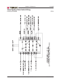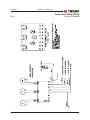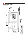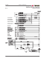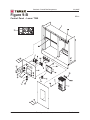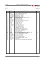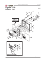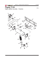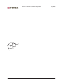
1
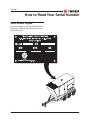
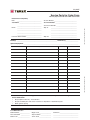
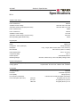
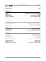
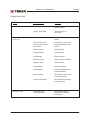
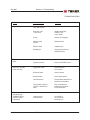
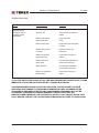
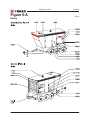
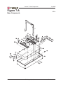
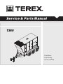
Service & Par ts Manual
T360
First Edition
First Printing
Part No. 833019
July 2007
Introduction
Important
Serial Number Information
Read, understand and obey the safety rules and
operating instructions in the appropriate Operator's
Manual on your machine before attempting any
maintenance procedure.
TEREX Corporation offers the following manuals for
these models:
Basic mechanical, hydraulic and electrical
skills are required to perform most procedures.
However, several procedures require specialized
skills, tools, lifting equipment and a suitable
workshop. In these instances, we strongly
recommend that maintenance and repair be
performed at an authorized TEREX dealer
service center.
TEREX T360 Operator's Manual, ....................... 133005
First Edition
Title
Part No.
TEREX T360 Service & Parts Manual, ............... 833019
First Edition
Newage Generator Manual ................................ 836430
Cummins Engine Manual ................................... 125558
Cascade Controller Manual ............................... 833011
Dexter Axle Manual ............................................ 833014
Technical Publications
TEREX Corporation has endeavored to deliver the
highest degree of accuracy possible. However,
continuous improvement of our products is a
TEREX policy. Therefore, product specifications
are subject to change without notice.
Readers are encouraged to notify TEREX of errors
and send in suggestions for improvement. All
communications will be carefully considered for
future printings of this and all other manuals.
Contact Us:
Copyright © 2007 by TEREX Corporation
www.TEREX.com
833019 Rev A July 2007
First Edition, First Printing
"TEREX" is a registered trademark of TEREX
Corporation in the USA and many other countries.
"Super Quiet" is a trademark of TEREX
Corporation.
Printed on recycled paper
Printed in U.S.A.
ii
T360 Super Quiet Generator
Part No. 833019
July 2007
How to Read Your Serial Number
Serial Number Legend
The serial number plate on your T360 Super Quiet
Generator is located on the twist lock area of the
lower control panel.
Part No. 833019
T360 Super Quiet Generator
iii
July 2007
This page intentionally left blank.
iv
T360 Super Quiet Generator
Part No. 833019
July 2007
Section 1 • Safety Rules
Safety Rules
Danger
Failure to obey the instructions and safety rules
in this manual and the appropriate Operator's
Manual on your machine will result in death or
serious injury.
Many of the hazards identified in the
operator’s manual are also safety hazards
when maintenance and repair procedures
are performed.
Do Not Perform Maintenance
Unless:
You are trained and qualified to perform
maintenance on this machine.
You read, understand and obey:
- manufacturer’s instructions and safety rules
- employer’s safety rules and worksite
regulations
- applicable governmental regulations
You have the appropriate tools, lifting
equipment and a suitable workshop.
Part No. 833019
T360 Super Quiet Generator
v
Section 1 • Safety Rules
July 2007
SAFETY RULES
Personal Safety
Workplace Safety
Any person working on or around a machine must
be aware of all known safety hazards. Personal
safety and the continued safe operation of the
machine should be your top priority.
Be sure to keep sparks, flames and
lighted tobacco away from flammable and
combustible materials like battery gases
and engine fuels. Always have an approved fire
extinguisher within easy reach.
Read each procedure thoroughly. This
manual and the decals on the machine,
use signal words to identify the following:
Safety alert symbol—used to alert
personnel to potential personal
injury hazards. Obey all safety
messages that follow this symbol
to avoid possible injury or death.
Indicates an imminently hazardous
situation which, if not avoided, will
result in death or serious injury.
Indicates a potentially hazardous
situation which, if not avoided,
could result in death or serious
injury.
Indicates a potentially hazardous
situation which, if not avoided,
may cause minor or moderate
injury.
Indicates a potentially hazardous
situation which, if not avoided,
may result in property damage.
Be sure that all tools and working areas
are properly maintained and ready for use.
Keep work surfaces clean and free of
debris that could get into machine components and
cause damage.
Be sure any forklift, overhead crane or
other lifting or supporting device is fully
capable of supporting and stabilizing the
weight to be lifted. Use only chains or straps that
are in good condition and of ample capacity.
Be sure that fasteners intended for one
time use (i.e., cotter pins and self-locking
nuts) are not reused. These components
may fail if they are used a second time.
Be sure to properly dispose of old oil or
other fluids. Use an approved container.
Please be environmentally safe.
Be sure that your workshop or work area is
properly ventilated and well lit.
Be sure to wear protective eye wear and
other protective clothing if the situation
warrants it.
Be aware of potential crushing hazards
such as moving parts, free swinging or
unsecured components when lifting or
placing loads. Always wear approved steel-toed
shoes.
vi
T360 Super Quiet Generator
Part No. 833019
July 2007
Table of Contents
Introduction
Important Information - Introduction .................................................................... ii
How to Read Your Serial Number ...................................................................... iii
Parts Stocking List ............................................................................................ x
How to Order Parts ............................................................................................ xi
Service Parts Fax Order Form ......................................................................... xii
Section 1
Safety Rules
General Safety Rules ........................................................................................ v
Section 2
Section 3
Rev
Specifications
A
Specifications .............................................................................................. 2 - 1
A
Specifications (Continued) ............................................................................ 2 - 2
A
Torque Specifications ................................................................................... 2 - 3
A
Generator Torque Specifications .................................................................. 2 - 4
Rev
Scheduled Maintenance Procedures
Introduction .................................................................................................. 3 - 1
Pre-delivery Preparation Report .................................................................... 3 - 2
A
Maintenance Schedules
Cummins Lubrication and Maintenance Service Intervals ............................. 3 - 3
Newage Generators Maintenance Schedule ................................................. 3 - 5
Section 4
Rev
Troubleshooting
Introduction .................................................................................................. 4 - 1
A
Part No. 833019
Troubleshooting Guide .................................................................................. 4 - 2
T360 Super Quiet Generator
vii
July 2007
TABLE OF CONTENTS
Section 5
Section 6
Rev
A
Introduction .................................................................................................. 5 - 1
A
Electrical Schematic - Control Panel Wiring for
Murphy Cascade Controller .......................................................................... 5 - 2
A
Electrical Schematic - Distribution Panel Wiring ........................................... 5 - 3
A
Electrical Schematic - Stack Switch ............................................................ 5 - 4
A
Electrical Schematic- Overcurrent Relay ...................................................... 5 - 5
A
Electrical Schematic - Standard Generator Wiring ........................................ 5 - 6
A
Electrical Schematic - Idle-Run Wiring (Cummins) ....................................... 5 - 7
Rev
A
Section 7
Section 8
Section 9
viii
Schematics
Rev
Decals
Figure 6-A
Decals ................................................................................. 6 - 2
Base Components
A
Figure 7-A
Base Components ............................................................... 7 - 2
A
Figure 7-B
Base Components ............................................................... 7 - 4
Rev
Cabinet Components
A
Figure 8-A
Cabinet Components - Panels .............................................. 8 - 2
A
Figure 8-B
Cabinet Components - Doors ............................................... 8 - 4
Rev
Control Box Components
A
Figure 9-A
Control Panel - Upper - T360C ............................................. 9 - 2
A
Figure 9-B
Control Panel - Lower - T360C ............................................. 9 - 4
T360 Super Quiet Generator
Part No. 833019
July 2007
TABLE OF CONTENTS
Section 10
Rev Distribution Panel
A
Section 11
Section 12
Distribution Panel ............................................................... 10 - 2
Rev Engine & Genset Components
A
Figure 11-A
Engine Genset Assembly - Cummins ................................ 11 - 2
A
Figure 11-B
Engine Muffler Assembly - Cummins ................................. 11 - 4
Rev Trailer Components
A
Part No. 833019
Figure 10-A
Figure 12-A
Trailer Components ........................................................... 12 - 2
T360 Super Quiet Generator
ix
July 2007
Parts Stocking List
Required Parts
The following parts are required to perform
maintenance procedures as outlined in the
TEREX T360 Parts and Service Manual.
Description
Part No.
Cummins QSM11G4 Models
Oil Filter .............................................................. 125550
Air Filter - Primary .............................................. 125561
Air Filter - Secondary ......................................... 125562
Fuel Filter ........................................................... 125551
Belt ..................................................................... 125552
x
T360 Super Quiet Generator
Part No. 833019
July 2007
How To Order Parts
Please be prepared with the following information
when ordering replacement parts for your TEREX
product:
Machine model number
Machine serial number
Terex part number
Part description and quantity
Purchase order number
"Ship to" address
Desired method of shipment
Name and telephone number of the
authorized TEREX Distributor in your area
TEREX North America
Telephone (803) 324-3011
Toll Free (800) 433-3026 in U.S.A. and Canada
Fax (803) 366-1101
Use the Service Parts Fax Order Form on the
next page and fax your order to our Parts
Department.
If you don't know the name of your authorized
distributor, or if your area is not currently serviced
by an authorized distributor, please call TEREX
Corporation.
Machine Information
Model
Serial Number
Date of Purchase
Authorized TEREX Distributor
Phone Number
Part No. 833019
T360 Super Quiet Generator
xi
July 2007
Service Parts fax Order Form
FAX TO: (800) 633-5534 OR TOLL FREE: 800-433-3026
Please fill out completely
_________________________________
Account Number _______________________________
Your Name ______________________________
Your Fax Number _____________________________
_________________________________
Your Phone Number ____________________________
_________________________________
Ship To
Bill To
___________________________________
_________________________________
___________________________________
_________________________________
___________________________________
_________________________________
Purchase Order Number ____________________
___________________________________
Ship Via
___________________________________
Model(s) ______________________________________________________ Serial No.(s) _________________
Optional Equipment __________________________________________________________________________
Description
Quantity
Price
remove this page and make copies
Part Number
remove this page and make copies
Date
All backordered parts will be shipped when available via the same ship method as the original order
unless noted below:
o
Ship complete order only - no backorders
o
Ship all available parts and contact customer on disposition of backordered parts
o
Other (please specify)
FOR TEREX USE ONLY
Order Number ______________
Origin Code ________________
Comments _________________________
Date Scheduled ____________
Ship Condition ______________
__________________________________
Order Total ________________
Terms Code ________________
__________________________________
T360 Super Quiet Generator
Part No. 833019
July 2007
Section 2 • Specifications
Specifications
REV A
System Power Output
Prime 3 Phase Power
288 kW
Prime 3 Phase kVA
360 kVA
Available 3 Phase Voltage
208 / 220 / 240 / 440 / 480
Associated 3 Phase Amps (0.8 power factor)
999 / 945 / 866 / 472 / 433
Prime 1 Phase Power
160kW
Prime 1 Phase kVA
160 kVA
Available 1 Phase Voltage
120 / 240
Associated 1 Phase Amps (1.0 power factor)
1333 / 667
Max Amp Rating (Main Breaker Size)
1200 A
Engine Specs
Manufacturer
Cummins
Model
QSM11-G4
Horsepower - Prime (1800 rpm)
426 hp (318 kWm)
Description
6-Cyl., 4 Cycle, Water Cooled, OHV, In-Line, Direct Inj.
Bore & Stroke
4.92 x 5.79 in. (125mm x 170mm)
Piston Displacement
661 cu. In (10.8 L)
Compression Ratio
16.3 : 1
Exhaust System
Critical Grade Silencer
Monitoring Gauges
Oil Press., Water Temp., Fuel Level, Battery Voltage, Hours
Engine Cooling System
Coolant Capacity - engine only
2.5 gal (9.5 L)
Cooling System
Liquid Cooled - Air to Air CAC - Rated to 105° F Ambient
Fuel System
Fuel Specification
#2 Diesel
Fuel Filter
Fuel/Water Separator
Fuel Capacity
400 gal (1514 L)
Fuel Tank and Containment
Fuel Consumption (Run Time)
Part No. 833019
Internal Fuel Tank with Fluid Spills Containment
Full Load
20.7 gal/hr (78 L/hr) 19 hr
3/4 Load
15.5 gal/hr (59 L/hr) 25.8 hr
Half Load
10.6 gal/hr (40 L/hr) 37.7 hr
T360 Super Quiet Generator
2-1
Section 2 • Specifications
July 2007
SPECIFICATIONS
REV A
Generator Specs
Rating (0.8 power factor)
Description
352 kW 3 Phase @ 480/240V
Brushless, 4 Pole, Synchronous, Single Bearing
Insulation
Class H
Temperature Rating
125° C Rise Over 40° C Ambient
Automatic Voltage Regulator
External, Solid State, Adjustable
Voltage Regulation
+/- 1%
Frequency (Speed)
60 Hertz (1800 RPM)
System Controls
Governor
Protection (Safety Shutdowns)
ECM Controlled
Low Oil Pressure, High Water Temperature
Overcrank, Overspeed, Underspeed
Generator Gauges
Voltmeter, Ammeter, Hertz Meter
Distribution
Receptacles, 120 V
2 Each 20 Amp GFCI Duplex
Receptacles, 240 V
3 Each 50 Amp Tempower T/L
Primary Distribution
5 Lug Terminals with Mainline Circuit Breaker
Packaging
Enclosure
Sound Attenuated, Weatherproof with Lockable Doors
Sound Levels
72 dBA at 23 ft. (7 meters)
Lifting System
Roof Mounted, Single Point
Weight Empty (No Trailer)
10450 lb. (4740 kg)
Weight Full (No Trailer)
13227 lb. (6000 kg)
Dimensions - L x W x H (No Trailer)
165 x 62 x 94 in. (419 x 157 x 2394 cm)
Weight Empty with Trailer
13120 lb. (5964 kg)
Weight Full with Trailer
15890 lb. (7223 kg)
Dimensions - L x W x H with Trailer
2-2
230 x 88 x 114 in. (584 x 224 x 290 cm)
T360 Super Quiet Generator
Part No. 833019
Section 2 • Specifications
July 2007
REV A
SPECIFICATIONS
SAE FASTENER TORQUE CHART
• This chart is to be used as a guide only unless noted elsewhere in this manual •
SIZE
Grade 5
THREAD
LUBED
20
28
1/4
5/16
3/8
7/16
1/2
9/16
5/8
3/4
7/8
1
1.125
1.25
1.5
LUBED
DRY
DRY
in- lbs
Nm
in- lbs
Nm
in- lbs
Nm
in- lbs
Nm
in- lbs
Nm
100
90
11.3
10.1
80
120
9
13.5
140
120
15.8
13.5
110
160
12.4
18
130
140
14.7
15.8
LUBED
18
24
16
24
14
20
13
20
12
18
11
18
10
16
9
14
8
12
7
12
7
12
6
12
A574 High Strength
Black Oxide Bolts
LUBED
Grade 8
DRY
LUBED
DRY
LUBED
f t - lbs
Nm
f t - lbs
Nm
f t - lbs
Nm
f t - lbs
Nm
f t - lbs
Nm
13
14
23
26
37
41
57
64
80
90
110
130
200
220
320
350
480
530
590
670
840
930
1460
1640
17.6
19
31.2
35.2
50.1
55.5
77.3
86.7
108.4
122
149
176
271
298
433
474
650
718
800
908
1138
1260
1979
2223
17
19
31
35
49
55
75
85
110
120
150
170
270
300
430
470
640
710
790
890
1120
1240
1950
2190
23
25.7
42
47.4
66.4
74.5
101.6
115
149
162
203
230
366
406
583
637
867
962
1071
1206
1518
1681
2643
2969
18
20
33
37
50
60
80
90
120
130
160
180
280
310
450
500
680
750
970
1080
1360
1510
2370
2670
24
27.1
44.7
50.1
67.8
81.3
108.4
122
162
176
217
244
379
420
610
678
922
1016
1315
1464
1844
2047
3213
3620
25
27
44
49
70
80
110
120
150
170
210
240
380
420
610
670
910
990
1290
1440
1820
2010
3160
3560
33.9
36.6
59.6
66.4
94.7
108.4
149
162
203
230
284
325
515
569
827
908
1233
1342
1749
1952
2467
2725
4284
4826
21
24
38
43
61
68
93
105
130
140
180
200
320
350
510
560
770
840
1090
1220
1530
1700
2670
3000
28.4
32.5
51.5
58.3
82.7
92.1
126
142
176
189
244
271
433
474
691
759
1044
1139
1477
1654
2074
2304
3620
4067
METRIC FASTENER TORQUE CHART
• This chart is to be used as a guide only unless noted elsewhere in this manual •
Class 4.6
Size
(m m )
5
6
7
LUBED
DRY
LUBED
Class 10.9
8.8
DRY
LUBED
Class 12.9
10.9
DRY
LUBED
12.9
DRY
in- lbs
Nm
in- lbs
Nm
in- lbs
Nm
in- lbs
Nm
in- lbs
Nm
in- lbs
Nm
in- lbs
Nm
in- lbs
Nm
16
19
45
1.8
3.05
5.12
21
36
60
2.4
4.07
6.83
41
69
116
4.63
7.87
13.2
54
93
155
6.18
10.5
17.6
58
100
167
6.63
11.3
18.9
78
132
223
8.84
15
25.2
68
116
1.95
7.75
13.2
22.1
91
155
260
10.3
17.6
29.4
LUBED
8
10
12
14
16
18
20
22
24
Class 8.8
4.6
DRY
LUBED
DRY
LUBED
DRY
LUBED
DRY
f t - lbs
Nm
f t - lbs
Nm
f t - lbs
Nm
f t - lbs
Nm
f t - lbs
Nm
f t - lbs
Nm
f t - lbs
Nm
f t - lbs
Nm
5.4
10.8
18.9
30.1
46.9
64.5
91
124
157
7.41
14.7
25.6
40.8
63.6
87.5
124
169
214
7.2
14.4
25.1
40
62.5
86.2
121
166
210
9.88
19.6
34.1
54.3
84.8
117
165
225
285
14
27.9
48.6
77.4
125
171
243
331
420
19.1
37.8
66
105
170
233
330
450
570
18.8
37.2
64.9
103
166
229
325
442
562
25.5
50.5
88
140
226
311
441
600
762
20.1
39.9
69.7
110
173
238
337
458
583
27.3
54.1
94.5
150
235
323
458
622
791
26.9
53.2
92.2
147
230
317
450
612
778
36.5
72.2
125
200
313
430
610
830
1055
23.6
46.7
81
129
202
278
394
536
682
32
63.3
110
175
274
377
535
727
925
31.4
62.3
108
172
269
371
525
715
909
42.6
84.4
147
234
365
503
713
970
1233
Part No. 833019
T360 Super Quiet Generator
2-3
Section 2 • Specifications
July 2007
GENERATOR TORQUE SPECIFICATIONS
2-4
Generator
FT*LB
Flex Plate to Flywheel
70
Generator Case to Bellhousing
45
5/8-11" Socket Head Cap Screws for Lifting Channel
190
1/2-13" Hex Head Screws for Lifting Channel
70
Genset Isolators
70
T360 Super Quiet Generator
Part No. 833019
Section 3 • Scheduled Maintenance Procedures
July 2007
Scheduled Maintenance Procedures
About This Section
This section contains detailed procedures for each
scheduled maintenance inspection.
Each procedure includes a description, safety
warnings and step-by-step instructions.
Observe and Obey:
Symbols Legend
Safety alert symbol—used to alert
personnel to potential personal
injury hazards. Obey all safety
messages that follow this symbol
to avoid possible injury or death.
Maintenance inspections shall be completed by
a person trained and qualified on the
maintenance of this machine.
Scheduled maintenance inspections shall be
completed as specified using the supplied
Lubrication and Maintenance Service Interval
Charts provided in this section.
Used to indicate the presence of
an imminently hazardous situation
which, if not avoided, will result in
death or serious injury.
Failure to perform each procedure
as presented and scheduled could
result in death, serious injury or
substantial damage.
Used to indicate the presence of a
potentially hazardous situation
which, if not avoided, could result
in death or serious injury.
Immediately tag and remove from service a
damaged or malfunctioning machine.
Used to indicate the presence of a
potentially hazardous situation
which, if not avoided, may cause
minor or moderate injury.
Repair any machine damage or malfunction
before operating the machine.
Keep records on all inspections for three years.
Machines that have been out of service for a
period longer than 3 months must complete the
quarterly inspection.
Unless otherwise specified, perform each
maintenance procedure with the machine in the
following configuration:
Used to indicate operation or
maintenance information.
Indicates that a specific result is expected after
performing a series of steps.
Indicates that an incorrect result has occurred
after performing a series of steps.
· Machine parked on a firm, level surface
· Toggle switch in the "OFF" position
· Wheels chocked
Part No. 833019
T360 Super Quiet Generator
3-1
Pre-Deliver
Pre-Deliveryy Preparation
Fundamentals
Instructions
It is the responsibility of the dealer to perform the
Pre-delivery Preparation.
Use the operator’s manual on your machine.
The Pre-delivery Preparation is performed prior to each
delivery. The inspection is designed to discover if anything
is apparently wrong with a machine before it is put into
service.
A damaged or modified machine must never be used. If
damage or any variation from factory delivered condition is
discovered, the machine must be tagged and removed
from service.
Repairs to the machine may only be made by a qualified
service technician, according to the manufacturer's
specifications.
Scheduled maintenance inspections shall be performed by
qualified service technicians, according to the
manufacturer's specifications and the requirements listed
in the responsibilities manual.
The Pre-delivery Preparation consists of completing the
Pre-operation Inspection, the Maintenance items and the
Function Tests.
Use this form to record the results. Place a check in the
appropriate box after each part is completed. Follow the
instructions in the operator’s manual.
If any inspection receives an N, remove the machine from
service, repair and re-inspect it. After repair, place a check
in the R box.
Legend
Y = yes, completed
N = no, unable to complete
R = repaired
Comments
Pre-Delivery Preparation
Pre-operation inspection completed
Maintenance items completed
Function tests completed
Model
Serial number
Date
Machine owner
Inspected by (print)
Inspector signature
Inspector title
Inspector company
TEREX North America
P.O. BOX 3147
Rock Hill, SC 29732 USA
Toll Free (800) 433-3026 in U.S.A. and Canada
Copyright © 2006 by TEREX Corporation. TEREX® is a registered trademark of TEREX
Corporation.
Rev B
Y
N
R
July 2007
Section 3 • Scheduled Maintenance Procedures
Maintenance Schedules
REV A
CUMMINS LUBRICATION AND MAINTENANCE SERVICE INTERVALS
ITEM
DAILY
50 Hrs or
Wkly
500 Hrs or
12 Mths
1000 Hrs
2000 Hrs
•
Inspect, adjust or replace alternator or fan belt
Check cooling system coolant level
•
•
•
•
Check driven equipment
Inspect engine air cleaner service indicator
Check engine oil level
Drain fuel system primary filter/water
separator
Walk around inspection
•
•
•
Drain tank water and sediment
•
•
•
•
•
•
•
Check battery electrolyte level
Clean/replace engine air cleaner element
Inspect/clean engine ground
Change engine oil and filter
Replace water separator element
Replace fuel system secondary filter
Inspect/replace hoses and clamps
•
Inspect/adjust engine valve lash
•
•
•
•
•
•
Inspect aftercooler core
Inspect alternator
Inspect engine mounts
Inspect starting motor
Inspect turbocharger
Inspect water pump
ITEM
2 Yrs
3000 Hrs
3000 Hrs or
2 Yrs
6000 Hrs or 12000 Hrs
3 Yrs
or 6 Yrs
•
Change cooling system coolant
•
Test/change fuel injector
Change cooling system coolant
(commercial heavy duty)
•
•
Clean/test aftercooler core
Add cooling system coolant extender (ELC)
•
•
Change cooling system coolant (ELC)
Part No. 833019
4000 Hrs
T360 Super Quiet Generator
3-3
Section 3 • Scheduled Maintenance Procedures
July 2007
MAINTENANCE SCHEDULES CONTINUED
REV A
NEWAGE GENERATORS MAINTENANCE SCHEDULE
ITEM
DAILY
250 Hours 1500 Hours
15000
4500 Hours
or 3
or 12
Hours or 19
or 3 Years
Months
Months
Years
•
Visual inspection
Visual inspection plus running audible check
Measure stator winding insulation resistance
and record
Monitor bearing/s condition
Remove terminal box lid and check
connections
Re-grease bearings
•
•
•
•
•
•
•
•
•
•
•
Measure vibration levels
Replace bearing/s
Replace NDE o-ring
Inspect bearing housings
Inspect winding conditions
Inspect rotating diode assembly
*Refer to the manufacturers manuals for detailed maintence intervals and instructions. If the
information in the manufacturer's manual differs from that in this manual the manufacturer's manual
should take precedence.
3-4
T360 Super Quiet Generator
Part No. 833019
July 2007
Section 4 • Troubleshooting
Troubleshooting
Before Troubleshooting:
Read, understand and obey the safety rules
and operating instructions in the appropriate
operator's manual on your machine.
Be sure that all necessary tools and test
equipment are available and ready for use.
Observe and Obey:
Troubleshooting and repair procedures shall be
completed by a person trained and qualified on
the repair of this machine.
Be aware of the following hazards and follow
generally accepted safe workshop practices.
Immediately tag and remove from service a
damaged or malfunctioning machine.
Repair any machine damage or malfunction
before operating the machine.
Unless otherwise specified, perform each
repair procedure with the machine in the
following configuration:
· Machine parked on a firm, level surface.
· Wheels chocked.
· Toggle switch in "OFF" position.
Electrocution hazard. Exposure to
electrically charged circuits could
result in death or serious injury.
Remove all rings, watches and
other jewelry.
Electrocution hazard. Attempting
to sevice the machine before the
capacitors are fully discharged will
result in death or serious injury.
High voltage. Exposure to
electrical wires or electrical current
will result in death or serious
injury. Remove all rings, watches
and other jewelry. Turn off all
power when not needed for
testing. Use extreme caution when
working with high voltage electrical
components.
Burn hazard. Contact with hot
engine components may cause
severe burns. Use caution when
working around a hot engine.
Part No. 833019
T360 Super Quiet Generator
4-1
Section 4 • Troubleshooting
July 2007
Troubleshooting Guide
The engine/generator set is tested and set at the factory for proper operation in the field. These units
should never require additional adjustments in the field. If needed, adjustments should only be made by a
qualified service technician, otherwise the manufacturer’s warranty may become void.
FAULT
POSSIBLE CAUSE
SOLUTION
No generator output voltage
Circuit breaker tripped
Reset circuit breaker
Voltage regulator
Check voltage regulator wiring
Defective voltage regulator
Replace voltage regulator
Defective Selector Switch
By pass by hardwiring generator
Defective generator
Refer to generator manual
Voltage adjustment
set too low
Adjust voltage potentiometer
Defective potentiometer
By pass or replace
Low engine speed
Call TEREX Service
Loose wire on voltage
selector switch
Check wiring
Fluctuating or surging
engine speed
Check engine fuel, oil,
and air filters
Loose wire on voltage
regulator sensing circuit
Check wiring
Defective voltage regulator
Replace voltage regulator
Voltage adjustment
potentiometer
Adjust potentiometer
High engine speed
Call TEREX Service
Low generator output voltage
High generator
output voltage
4-2
T360 Super Quiet Generator
Part No. 833019
July 2007
Section 4 • Troubleshooting
TROUBLESHOOTING
FAULT
POSSIBLE CAUSE
SOLUTION
High generator
output voltage
Defective automatic
voltage regulator
Replace voltage
regulator
Loose wire on voltage
adjustment potentiometer
Check wiring
Neutral binding strap
not in place.
Install neutral binding strap
An “ON/OFF” type
load may be the cause
Redistribute load if
possible
Fluctuating or surging
engine speed
Check engine fuel, oil,
and air filters
Loose wiring in generator
Check connections
Automatic voltage regulator
stability setting may be
wrong
Call TEREX Service
Loose wire on the automatic
voltage regulator sensing lead
Check wiring
Engine speed adjustment
has slipped
Call TEREX Service
Clogged fuel system
Check for air leaks, clogged fuel
filter, kinked fuel line, or
clogged fuel pick-up tube
Blocked air intake
Check air filter
Blocked exhaust system
Check engine exhaust
system, remove
obstructions
Contaminated fuel
Check fuel/water separator and
fuel tank for contamination.
Replace fuel if needed
Defective governor on engine
Call TEREX Service
Fluctuating generator
output voltage
Low engine speed
Part No. 833019
T360 Super Quiet Generator
4-3
Section 4 • Troubleshooting
July 2007
TROUBLESHOOTING
FAULT
POSSIBLE CAUSE
SOLUTION
Low Speed
Defective injectors on engine
Have injectors checked by a
qualified technician
“Surging” engine speed
Check engine fuel, oil,
and air filters
Unit out of fuel
Check fuel level in tank, fill as
needed
Loose or broken wire in
control circuit fuel injection
pump solenoid
Check wiring to verify 12V DC
is being supplied to the pump
solenoid
Defective solenoid
Replace solenoid
Clogged fuel system
Check fuel system
Air in fuel system
“Bleed” fuel system
Defective fuel pump
Check and replace if defective
Clogged air intake
Check air cleaner
Clogged exhaust
Check exhaust system
Contaminated fuel
Check fuel/water separator and
tank for contamination
Defective injectors
Have injection system checked
by a trained technician
Lost engine compression
Have compression checked by
a trained technician
Loose battery cable
or discharged battery
Check cables and battery
electrolyte level. Recharge
as necessary
Engine turns over (cranks),
but won’t run
Engine won’t crank
4-4
T360 Super Quiet Generator
Part No. 833019
July 2007
Section 4 • Troubleshooting
TROUBLESHOOTING
FAULT
POSSIBLE CAUSE
SOLUTION
Engine won’t crank
Engine “ON/OFF” switch
set in “OFF” position
Check switch position
Blown fuse in DC
control circuit
Replace with 25 Amp.
SLO-BLO TYPE
fuse if needed.
E-Stop
Check to see if engaged
Defective starter
solenoid
Replace solenoid
Defective starter
Replace starter
Seized engine
Have engine checked by a
qualified technician
Engine runs, but loses
speed
Unit is overloaded
Reduce load
Improper connection
Check or Call TEREX Service
Engine runs, but loses
power under load
Clogged fuel system
Check fuel system
air in fuel lines
Blocked air intake
Check air cleaner
Blocked exhaust
Check exhaust system
Contaminated fuel
Check fuel/water separator and
fuel tank for contamination
Faulty governor, defective
injectors, or defective fuel
pump
Have unit checked by a
trained service technician
for all of these items
Oil Pressure Switch
Not opening
Improper coolant
or water mixture
Use a 50/50 on
mix of water and
anti-freeze only
Engine shuts down
automatically and
TROUBLE LIGHT on
CONTROL PANEL
is illuminated
Part No. 833019
T360 Super Quiet Generator
4-5
Section 4 • Troubleshooting
July 2007
TROUBLESHOOTING
FAULT
POSSIBLE CAUSE
SOLUTION
Engine shuts down
automatically and
TROUBLE LIGHT on
CONTROL PANEL
is illuminated
Overloaded engine
Reduce load
Broken fan belt
Inspect fan belt and replace as
needed
Defective thermostat or
thermocouple switch
Inspect thermostat
switch
Defective water pump
Inspect water pump and replace
if needed
Blocked cooling air inlet
or exhaust
Inspect and remove any
obstructions
Defective or grounded
temperature switch
Inspect switch and repair or
replace
Defective injectors or
injector pump
Have the engine inspected by a
trained service technician
Defective oil pump
Have the engine inspected by
a trained service technician
Defective or grounded oil
pressure switch
Inspect switch and repair or
replace
IF YOU FEEL AN ELECTRIC SHOCK AT ANY TIME WHILE OPERATING THIS UNIT, SHUT IT DOWN
IMMEDIATELY! HAVE THE UNIT INSPECTED BY A TRAINED ELECTRICIAN.
THIS ENGINE/GENERATOR SET IS FACTORY INSTALLED, TESTED, AND SET FOR FIELD
OPERATION. ANY DAMAGE TO THE ENGINE OR GENERATOR UNITS OCCURRING AFTER
ADJUSTMENTS ARE MADE IN THE FIELD BY UNAUTHORIZED PERSONNEL WILL NOT BE
COVERED BY YOUR MANUFACTURER’S WARRANTY AND WILL ALSO VOID THE
MANUFACTURER’S WARRANTY ON THIS PARTICULAR UNIT. IF YOU CAN NOT REACH YOUR
LOCAL DEALER, CONTACT THE FACTORY SERVICE MANAGER TOLL FREE AT 1-800-433-3026.
4-6
T360 Super Quiet Generator
Part No. 833019
July 2007
Section 4 • Troubleshooting
TROUBLESHOOTING
Electrical Troubleshooting
5 Components that cause voltage
related problems
Generator
Test resistance of field, stator and exciter windings.
Contact TEREX for procedures or repair facility
recommended by generator manufacturer.
Potentiometer
Connects to voltage regulator. Bypass potentiometer by unplugging from voltage regulator and
installing jumper on 2 male spades on regulator.
Voltage Regulator
(Located inside the generator rear housing.)
Measure DC voltage at F1 & F2. Normal voltage is
10 to 12 V DC. Remove 2 wires marked (F1,
X)(F2, X X) from voltage regulator. Connect wire
marked F1 to positive and F2 to negative of a 12
volt battery. Start unit and measure voltage. If unit
produces close to maximum output, replace
Automatic Voltage Regulator.
Voltage Selector Switch
The correct way to test is to disconnect from
generator and hard wire the generator into one
configuration. This will eliminate the switch from
the circuit and verify that the generator is functioning properly. All contacts should be checked
following the proper schematic with the switch
disconnected from the generator set. Actual loads
can cause failures in contacts that cannot be
duplicated using a meter.
Overcurrent Relay
THIS EQUIPMENT USES HIGH VOLTAGE
CIRCUITS CAPABLE OF CAUSING SERIOUS
INJURY OR DEATH! EXCERCISE EXTREME
CAUTION AROUND ANY ELECTRICAL
COMPONENT WHEN OPERATING THIS UNIT.
IT IS ESSENTIAL THAT ALL TEST INSTRUMENTS ARE REGULARLY CHECKED FOR
SAFETY, AND ANY CONNECTION LEADS,
PROBES, OR CLIPS, ARE CHECKED TO
ENSURE THAT THEY ARE SUITABLE FOR
THE VOLTAGE LEVELS BEING TESTED.
NEVER ATTEMPT TO TEST A "LIVE" GENERATOR UNLESS THERE IS ANOTHER COMPETENT PERSON PRESENT WHO CAN SWITCH
OFF THE POWER SUPPLY OR SHUT DOWN
THE ENGINE IN AN EMERGENCY.
NEVER EXPOSE "LIVE" CONNECTIONS UNLESS YOU HAVE CREATED A SAFE WORKING
AREA AROUND YOU. MAKE SURE YOU HAVE
MADE ALL OTHER PERSONS IN THE IMMEDIATE AREA FULLY AWARE OF WHAT YOU ARE
DOING.
•
This device causes the 3-phase breaker to trip
that supplies AC power to the distribution lugs if
uneven or excessive current is measured at the
distribution lugs. It is also connected to the 3phase door switch and will automatically trip the 3phase breaker when the door is open and prevents the breaker from being reset while it is open.
Part No. 833019
Procedure for testing
generator with no output
When a new generator is not producing voltage,
the testing or wiring personnel should first verify
that the unit is wired correctly! The stack switch
and generator leads should all be checked as
well as the breaker and sensing leads. If the
unit was not wired correctly and you flashed the
generator, you could burn up the unit. (Do not
forget to check the sensing leads!).
T360 Super Quiet Generator
4-7
Section 4 • Troubleshooting
July 2007
TROUBLESHOOTING
Procedure for testing
generator with no output
(cont.)
•
•
•
After performing the initial checks above,
remove the field wires from the voltage
regulator (F1 or X is positive and F2 or XX is
negative). Connect the battery + to the F1 or X
wire and battery - to the F2 or XX wire. Start the
engine and check for the rated voltage.
Hooking this up incorrectly will reverse
polarity and could damage the voltage
regulator and /or generator end. This check
should correct any voltage problems. If your
voltage does not come up to the rated voltage,
this indicates an internal problem with the
generator end. The output should be close to
proper voltage. Also, if the unit comes up to
voltage, check for even reading across the lines
if they are not this would mean you probably
have a problem with the wiring of the switch or
generator. If the generator voltage reads
correctly you know there is not a problem with
the generator end. Your problem is more than
likely with the voltage regulator. In this case,
you should contact the TEREX service
department.
If the voltage is uneven between the legs when
you apply 24 volts to the field wires you need to
recheck your wiring connections. (If you can
not find the problem hard wire the
generator!) After you have the field wire
connected start the unit again and check your
output voltage. It may still be necessary to flash
the fields to restore residual voltage. This needs
to be done with the unit off and the field wires
removed. (Do not flash the regulator, flash
the field wires)
As with any electrical device use extreme
caution when working around a running
generator it could cost you your life. Observe
proper polarity when working with the regulator
so you don’t break something that is not broken
to begin with, and if you are ever in doubt, ask.
4-8
INSTALLATION AND ANY WORK PERFORMED
ON THIS UNIT SHOULD BE DONE ONLY BY A
QUALIFIED ELECTRICIAN.
Procedure for changing the
voltage potentiometer
THIS EQUIPMENT USES HIGH VOLTAGE
CIRCUITS CAPABLE OF CAUSING SERIOUS
INJURY OR DEATH! EXCERCISE EXTREME
CAUTION AROUND ANY ELECTRICAL
COMPONENT WHEN OPERATING THIS UNIT.
INSTALLATION AND ANY WORK PERFORMED
ON THIS UNIT SHOULD BE DONE ONLY BY A
QUALIFIED ELECTRICIAN.
•
Make sure generator is turned off and e-stop is
engaged before opening control panel.
•
Locate the two wires going to the back of the
potentiometer. Both wires will be white with a
red stripe.
•
Disconnect both wires.
•
Once the wires are loose, go to the front of the
control panel and loosen the lock nut holding
the potentiometer.
•
Put the new potentiometer in its place and
retighten lock nut.
•
Reattach the disconnected wires that were
disconnected in step 3.
•
After completing the installation of the new
potentiometer go back and check all
connections to make sure everything is tight
and that no connections are loose, this includes
all other wiring on the back of the control panel
and on the inside of the control box.
•
You should now be able to restart the generator
and check for proper operation.
If any further adjustment is needed to the voltage of
the generator please call TEREX at 1-800-433-3026
for assistance.
T360 Super Quiet Generator
Part No. 833019
July 2007
Section 5 • Schematics
Schematics
REV A
About This Section
There are two groups of schematics in this section.
An illustration legend precedes each group of
drawings.
Electrical Schematics
Observe and Obey:
Electrocution hazard. Contact with
electrically charged circuits could
result in death or serious injury.
Remove all rings, watches and
other jewelry.
Troubleshooting and repair procedures shall be
completed by a person trained and qualified on
the repair of this machine.
Immediately tag and remove from service a
damaged or malfunctioning machine.
Repair any machine damage or malfunction
before operating the machine.
Before Troubleshooting:
General Repair Process
Malfunction
discovered
Read, understand and obey the safety rules
and operating instructions in the appropriate
operator's manual on your machine.
Be sure that all necessary tools and test
equipment are available and ready for use.
Part No. 833019
Identify
symptoms
Troubleshoot
problem
still exists
Return to
service
T360 Super Quiet Generator
problem
solved
Inspect
and test
Perform
repair
5-1
Section 5 • Schematics
July 2007
Control Panel Wiring
for Murphy Cascade Controller
Drawing #ES100029 (Standard)
5-2
REV A
T360 Super Quiet Generator
Part No. 833019
July 2007
Section 5 • Schematics
Distribution Panel Wiring
REV A
Part No. 833019
for T360 Series Single Phase Control
Drawing #ES100027
T360 Super Quiet Generator
5-3
Section 5 • Schematics
July 2007
Three Position Stack Switch Wiring
Drawing #ES100026
5-4
REV A
T360 Super Quiet Generator
Part No. 833019
July 2007
Section 5 • Schematics
Overcurrent Relay Wiring
Drawing #ES100006
REV A
Part No. 833019
T360 Super Quiet Generator
5-5
Section 5 • Schematics
July 2007
Standard Generator Wiring
for T360 Series
Drawing #ES100030
5-6
REV A
T360 Super Quiet Generator
Part No. 833019
July 2007
Section 5 • Schematics
Idle-Run Wiring (Cummins)
Drawing #ES100039
REV A
Part No. 833019
T360 Super Quiet Generator
5-7
Section 5 • Schematics
July 2007
REV A
This page intentionally left blank.
5-8
T360 Super Quiet Generator
Part No. 833019
July 2007
Section 6 • Decals
Section Six
Decals
Part No. 833019
T360 Super Quiet Generator
6-1
Section 6 • Decals
Figure 6-A
July 2007
REV A
Decals
6-2
T360 Super Quiet Generator
Part No. 833019
Section 7 • Base Components
July 2007
Section Seven
Base
Components
Part No. 833019
T360 Super Quiet Generator
7-1
Section 7 • Base Components
Figure 7-A
July 2007
REV A
Base Components
7-2
T360 Super Quiet Generator
Part No. 833019
Section 7 • Base Components
July 2007
REV A
FIGURE 7-A
ITEM #
1
2
3
4
5
6
7
8
9
10
11
12
13
14
15
16
17
18
19
20
21
22
23
24
25
26
27
28
29
30
31
32
33
34
35
36
PART #
125190
981635
991650
C33600300
990820
981660
990210
895371
792750
890796
C91001300
892915
C90700800
C90200300
C91100700
C90200600
C90800200
125064
C90900601
125062
993890
C15309
C91100300
C90200400
C90200250
C90101500
890787
796151
C43200601
990200
125361
125362
125360
125055
125268
125436
Part No. 833019
DESCRIPTION
WELDMENT, LIFTING HOOP
SCREW, 1/2-13 NC X 1HHC, GR5, ZP
WASHER, LOCK 1/2"
MOUNT, VIBRATION, YELLOW
SCREW, 1/2-13 NC X 2 HHC, GR 8, Y-ZINC
SCREW, 1/2-13 NC X 1-1/2 HHC, GRADE 5, ZP
WASHER, FLAT 1/2"
VALVE VACCUUM RELIEF 1/4"
CLAMP 7/16 TO 25/32 W/LINER
HOSE, FUEL, 5/8", BLACK
FITTING, BARB, 3/8" NPT 1/4" HB
PIPE, ELBOW, STREET 90*, 1/2 M X F BRASS
ADAPTER, 1/2"X1/4" REDUCER
BARB, 3/8" X 1/4" NPT, 90 DEGREE
HOSE, FUEL, 3/8"
BARB, 3/8" X 1/4" NPT
VALVE, NEEDLE, 1/4" FPT X 1/4" FPT
TANK, FUEL, 428 GAL
PLUG, PIPE, 3", SQUARE HEAD
BASE, WELDMENT, 5OO GAL CONTAIN
WASHER, LOCK 5/8"
SCREW, HEX CAP, 5/8-11" X 1.5", KEG Y ZINC, GR8
NYLON TUBING - CUT TO PROPER LENGTH
FITTING, PICKUP
BARB, 1/4" MNPT 1/2" ID HOSE
CLAMP, 11/16" X 1-1/4"
HOSE, FUEL, 1/2" ID
CAP, FUEL
SENDER, FUEL LEVEL, VDO
NUT, LOCK NYLON INSERT, 1/2-13NC, GR 2, ZPIN
WELDMENT, GENERATOR MOUNT, FRONT
WELDMENT, GENERATOR MOUNT, REAR
WELDMENT, ENGINE MOUNT BEAM
FRONT MOTOR MOUNT, CUMMINS QSM
BATTERY SUPPORT FORMING
HOSE END BARBED, 90 DEGREE
T360 Super Quiet Generator
QTY.
1
12
40
6
4
30
30
1
3
4
1
1
1
1
4
1
1
1
1
1
8
8
2
1
1
2
12
1
1
2
1
1
2
1
1
1
7-3
Section 7 • Base Components
Figure 7-B
July 2007
REV A
Base Components
7-4
T360 Super Quiet Generator
Part No. 833019
Section 7 • Base Components
July 2007
REV A
FIGURE 7-B
ITEM #
1
2
3
4
5
6
7
8
9
10
11
12
13
14
15
16
17
18
19
20
21
22
23
24
25
26
27
28
29
30
31
32
33
34
35
36
37
38
39
40
41
42
43
44
PART #
125048
125049
125561
125562
125093
125487
125036
125487
125092
125060
C90107200
897925
125038
125040
125434
125433
C90101500
125099
125172
125167
C42208705
125169
125377
C33700800
125283
125336
125268
125563
125041
125042
897923
C90106300
C90110200
125488
C51601500
C40162
990200
990210
125177
993890
C15309
990250
990260
990280
Part No. 833019
DESCRIPTION
AIR CLEANER ASSEMBLY, DUAL ELEMENT, INCLUDES 2-4
MOUNTING BAND, AIR CLEANER
ELEMENT, PRIMARY
ELEMENT, SECONDARY
ELBOW, RUBBER, 90DEG, 7 X 6
CLAMP
PIPE, AIR INTAKE
CLAMP
HUMP HOSE, RUBBER, REDUCING 6 X 4
AIR FILTER MOUNT-CUMMINS QSM11
CLAMP
HOSE, CAC, 4 ID X 8 LONG
PIPE, TURBO OUTLET
PIPE, CHARGE COOLER OUTLET
ELBOW, 90D, 8 MALE,SAEX-8 FEMPIPE
HOSE END, BARBED, RIGID, -8-8
CLAMP, 11/16 X 1-1/4 W/LINER
WELDMENT, FRONT CORNER, CONTROL SIDE
WELDMENT, RADIATOR TOP
WELDMENT, FRONT CORNER, DISTRIBUTION SIDE
SWITCH/SENSOR, COOLANT LEVEL
FORMING, RADIATOR BOTTOM
FORMING, PLENUM DRAIN
HOOK, BATTERY HOLD DOWN (PAIR)
FORMING, BATTERY HOLDDOWN, 2 X 4D
BATTERY, 12V, GROUP 4D, 1080 CCA, WET
BATTERY SUPPORT FORMING
FAN GUARD
PIPE, COOLANT PRESSURE
PIPE, COOLANT SUCTION
HOSE, CAC, 2.5 ID X 3', LONG
CLAMP
CLAMP, T-BOLT, 4.25"
CLAMP
SCREW, 8MM X 20MM
NUT, FIN HEX M8-1.25 P
NUT, LOCK NYLON INSERT, 1/2-13NC, GR 2, ZPIN
WASHER , FLAT 1/2"
REAR MOTOR MOUNT-CUMMINS QSM11
WASHER, LOCK 5/8"
SCREW, HEX CAP, 5/8-11" X 1.5", KEG Y, ZINC, GR8
SCREW, 3/4-10NC X 2HHC, GRADE 2, ZP
WASHER, LOCK, 3/4"
NUT, HEX 3/4-10NC, GRADE 2, ZP
T360 Super Quiet Generator
QTY.
1
2
1
1
1
1
1
1
1
1
8
4
1
1
2
2
2
1
1
1
1
1
1
2
1
2
1
1
1
1
4
8
1
1
2
2
4
4
2
6
6
2
2
2
7-5
Section 7 • Base Components
Figure 7-B
July 2007
REV A
Base Components (cont.)
7-6
T360 Super Quiet Generator
Part No. 833019
Section 7 • Base Components
July 2007
REV A
FIGURE 7-B
ITEM #
45
46
47
48
49
50
PART #
C90200600
C91100700
897922
C90400900
C90800200
792750
Part No. 833019
DESCRIPTION
BARB, 3/8" X 1/4" NPT
HOSE, FUEL, 3/8"
HOSE, HEATER, SILICONE, 1"
NIPPLE, PIPE, 1/4" X 1.5"
VALVE, NEEDLE, 1/4" FPT X 1/4" FPT
CLAMP, 7/16 TO 25/32
T360 Super Quiet Generator
QTY.
4
11
5
1
1
3
7-7
Section 7 • Base Components
July 2007
This page intentionally left blank.
7-8
T360 Super Quiet Generator
Part No. 833019
Section 8 • Cabinet Components
July 2007
Section Eight
Cabinet
Components
Part No. 833019
T360 Super Quiet Generator
8-1
Section 8 • Cabinet Components
Figure 8-A
July 2007
REV A
Cabinet Components - Panels
8-2
T360 Super Quiet Generator
Part No. 833019
Section 8 • Cabinet Components
July 2007
REV A
FIGURE 8-A
ITEM #
1
2
3
4
5
6
7
8
9
10
11
12
13
14
15
16
17
18
19
20
21
22
23
24
25
26
27
28
29
30
31
32
33
34
35
36
37
38
39
PART #
125082
993850
993422
990670
669174
720440
C71100500
125176
125079
125269
125178
125179
C51601570
C71100200
GUU401000
125271
125090
125272
125379
125443
125087
125285
993850
993422
125286
993830
125430
125187
125186
125443
125548
125573
125547
125595
125597
125603
125596
125674
125546
Part No. 833019
DESCRIPTION
FORMING, ROOF TOP
WASHER, FLAT 1/4, 5/8 S
SCREW, FLANGE 1/4-20 X .75 STAIN STEEL
RIVET, POP, 3/16 X 1/2, S/S, BLIND RIVET
PLATE, DECK, SCREW-OUT
WEATHERSTRIP, ADHESIVE 1/8 THICK X 1/2 WIDE
FOAM BLACK URETHANE 1"
WELDMENT, REAR CORNER, CONTROL SIDE
WELDMENT, BACK LOUVER PANEL
REAR LOUVER PANEL MESH
WELDMENT, REAR CORNER, DISTRIBUTION SIDE
WELDMENT, BOX TOP
SCREW, FLANGE, 3/8" X 3/4", PATCH
FOAM BLACK URETHANE 1/2"
1.5" INSULATION MELAMINE FOIL BAKED
FORMING, PLENUM, DISTRIBUTION SIDE
FORMING, PLENUM, CONTROL SIDE
FORMING, PLENUM FRONT, TOP
FORMING, PLENUM FRONT, BOTTOM
WELDMENT, PLENUM TOP GRILL
WELDMENT, TOP DOOR FRAME
WELDMENT, LIFTING ATTACHMENT
WASHER, FLAT 1/4, 5/8 S
SCREW, FLANGE 1/4-20 X .75 STAIN STEEL
PLATE, LIFT ATTACHMENT CLAMP
WASHER, FLAT 5/8"
SCREW, SHC, 5/8-11 X 7
WELDMENT, DOOR POST, DISTRIBUTION SIDE
WELDMENT, DOOR POST, CONTROL SIDE
WELDMENT, PLENUM TOP GRILL
PLENUM FRONT, INSIDE
SQUARE PLENUM RADIATOR DOOR
SQUARE PLENUM, DISTRIBUTION SIDE
SQUARE PLENUM PAN
SQUARE PLENUM LATCH POST
SQUARE PLENUM DOOR
SQUARE PLENUM DOOR POST
FORMING, SQUARE PLENUM, FRONT
SQUARE PLENUM, CONTROL SIDE
T360 Super Quiet Generator
QTY.
1
94
94
6
1
AR
AR
1
1
1
1
2
25
AR
AR
1
1
1
1
1
2
1
4
4
1
4
4
1
1
1
1
1
1
1
1
1
1
1
1
8-3
Section 8 • Cabinet Components
Figure 8-B
July 2007
REV A
Cabinet Components - Doors
8-4
T360 Super Quiet Generator
Part No. 833019
Section 8 • Cabinet Components
July 2007
REV A
FIGURE 8-B
ITEM #
1
2
3
4
5
6
7
8
9
10
11
12
13
14
15
16
17
18
19
20
PART #
GUU401100
CU54T021
C74100100
125084
C71100500
24514
C71014
990150
C74419
125540
990670
C51200000
125185
125541
125483
C41135000
C21353
981120
990170
794890
Part No. 833019
DESCRIPTION
TRIMLOCK SEAL 7/16"
WINDOW, CONTROL DOOR
GASKET, WINDOW, CONTROL DOOR
FORMING, CONTROL PANEL DOOR
FOAM BLACK URETHANE 1"
LITERATURE BOX
FLAT WASHER 11/16" OD
NUT, LOCK NYLON INSERT, 1/4-20NC, GR 2, ZP
SCREW, CARRIAGE, 1/4-20 X .75 STAINLESS STEEL
WELDMENT, ACCESS DOOR, RIGHT
RIVET, POP 3/16 X 1/2, S/S BLIND RIVET
LATCH, BLACK, KEY LOCK, ADJ T-HANDLE
FORMING, DISTRIBUTION PANEL DOOR
WELDMENT, ACCESS DOOR, LEFT
STOP, DOOR, RUBBER W/WASHER
RIVET, POP, 1/4" X 1/2"
CARRIAGE BOLT, 3/8-16 X 3/4
WASHER, FLAT, 3/8
NUT, LOCK NYLON INSERT 3/8-16NC, GR 2, ZPN
HINGE, STAINLESS STEEL, BLACK COATED
T360 Super Quiet Generator
QTY.
AR
1
5
1
AR
1
4
4
4
1
4
4
1
1
2
2
40
40
40
10
8-5
Section 8 • Cabinet Components
July 2007
This page intentionally left blank.
8-6
T360 Super Quiet Generator
Part No. 833019
Section 9 • Control Box Components
July 2007
Section Nine
Control Box
Components
Part No. 833019
T360 Super Quiet Generator
9-1
Section 9 • Control Box Components
Figure 9-A
July 2007
REV A
Control Panel - Upper T360
9-2
T360 Super Quiet Generator
Part No. 833019
Section 9 • Control Box Components
July 2007
REV A
FIGURE 9-A
ITEM #
1
2
3
4
5
6
7
8
9
10
11
12
13
14
15
16
17
18
19
20
21
22
23
24
25
26
27
28
29
30
31
32
33
34
35
36
37
38
39
40
41
42
43
PART #
125065
GCU300006
C42200500
682070
C42208400
C43101600
C43200400
260360
C43200300
C43200600
261341
C43100600
C43100400
C43101400
R980195
990400
981745
992040
C51800100
800008
C51600800
C51200201
CU43A050
C90103800
C51601550
686735
C42401700
C42404000
R660115
CDWV40150
CDWV40151
CDWV40152
853838
853813
R980900
C54400100
990110
990150
992120
996390
800030
C73000100
Part No. 833019
DESCRIPTION
WELDMENT, CONTROL BOX
CONTROL PANEL, CASCADE
POTENTIOMETER, VOLTAGE ADJUSTMENT
BREAKER, MINI, 1P, 15A
SWITCH, TOGGLE, SINGLE THROW
GAUGE, DC, 24VOLT
GAUGE, OIL PRESSURE
HOURMETER, 12V DC
GAUGE, WATER TEMP, 12V
GAUGE, FUEL
CASCADE CONTROLLER
INCLUDED IN ITEM 11
METER, VOLT
METER, FREQUENCY
METER, AMP, 0-1200
SCREW, 1/4-20NC X 3/4"
WASHER, LOCK, 1/4"
WASHER, FLAT, 1/4"
RIVET, POP, 3/16 X .602
LANYARD, NYLON
HARNESS, AC GAUGES TO GENERATOR
NUT, CLIP, 1/4"-20 X 3/4"
HINGE, PIANO, 9", SS
PLASTIC 1/8" X 10.5" X 33"
CLAMP, RUBBER COATED
SCREW, SELF-TAPPING, #10
RAIL, RELAY MOUNTING
RELAY, OVER CURRENT
TERMINAL STRIP, 6 POS
JUMPER TERMINAL STRIP
RELAY, 50A, BOSCH
RELAY BASE, 50A, BOSCH
RELAY PIN
DECAL: CONTROL PANEL, CASCADE
DECAL: KIT-RECEPTACLES
NUT, LOCK NYLON INSERT #8-32NF 18-8 S/S
SCREW, SET, 8-32X1/2"
SCREW, 1/4-20NCX1, HHC GRADE 2 ZP
NUT, LOCK NYLON INSERT, 1/4-20NC, GR 2, ZP
NUT, HEX, 1/4-20NC, GRADE 2, ZP
WASHER, LOCK STAR, 1/4" INT-EXT, ZP
HARNESS, DC ENGINE, T360
TRIM LOCK, 1/4"
T360 Super Quiet Generator
QTY.
1
1
1
1
1
1
1
1
1
1
1
1
1
1
6
6
6
10
1
1
6
2
1
1
1
1
1
1
1
2
2
6
1
1
1
1
1
1
1
1
1
AR
9-3
Section 9 • Control Box Components
Figure 9-B
July 2007
REV A
Control Panel - Lower T360
9-4
T360 Super Quiet Generator
Part No. 833019
Section 9 • Control Box Components
July 2007
REV A
FIGURE 9-B
ITEM # PART #
1
2
3
4
5
6
7
8
9
10
11
12
13
14
15
16
17
18
19
20
21
22
23
24
25
26
27
28
29
30
125065
125273
C42105500
C42103400
C42103600
684640
C42501100
981070
CF41T031
C47100300
R980195
990400
981745
C54400100
C51601442
66812
66817
686662
671278
853752
C73716
981205
991940
R980900
C51600800
C51600800
853813
C42500600
C73000100
682776
Part No. 833019
DESCRIPTION
WELDMENT, CONTROL BOX
PLATE, LOWER CONTROL PANEL
BREAKER, 1200A, 3POLE
BREAKER, 20A, 120/240V
BREAKER, 50A, 120/240V
RECEPTACLE, 20A, 120V, DUPLEX W/GFI
TRANSFORMER, 600:5
WASHER, FLAT 5/16"
TEMP POWER SLOPE
RECEPTACLE, TWISTLOCK, 50A, 240V
SCREW, 1/4-20NC X 3/4"
WASHER, LOCK, 1/4"
WASHER, FLAT, 1/4"
SCREW, SET, 8-32 X 1/2"
SCREW, FLANGE, 1/4"-20
E-STOP, PUSH BUTTON
EMERGENCY STOP, BASE
EMERGENCY STOP, FACE PLATE
BINDING POST FOR REMOTE START
DECAL: REMOTE START CN
SCREW, #6-32 X 1/2"
SCREW, 5/16-18NC X 6-1/2 HHC, GR 5, ZP
NUT, LOCK NYLON INSERT, 5/16-18NC, GR 2, ZP
NUT, LOCK NYLON INSERT, #8-32NF
NUT, CLIP, 1/4"-20 X 3/4"
NUT, CLIP, 1/4"-20 X 3/4"
DECAL: KIT-RECEPTACLES
TRANSFORMER, CURRENT, 1200:5
TRIM LOCK, 1/4"
RECEPTACLE, 15A, OPTIONAL, NOT STANDARD
T360 Super Quiet Generator
QTY.
1
1
1
2
3
2
3
4
1
3
8
8
8
4
6
1
1
1
1
1
16
4
4
10
6
16
1
1
AR
2
9-5
Section 9 • Control Box Components
July 2007
This page intentionally left blank.
9-6
T360 Super Quiet Generator
Part No. 833019
Section 10 • Distribution Panel
July 2007
Section Ten
Distribution
Panel
Part No. 833019
T360 Super Quiet Generator
10 - 1
Section 10 • Distribution Panel
Figure 10-A
July 2007
REV A
Distribution Panel
10 - 2
T360 Super Quiet Generator
Part No. 833019
Section 10 • Distribution Panel
July 2007
REV A
FIGURE 10-A
ITEM #
1
2
3
4
5
6
7
8
9
10
11
12
13
14
15
16
17
18
19
20
21
22
23
24
25
26
27
28
29
30
31
32
33
34
35
36
37
38
39
PART #
993422
993850
C51601441
125198
125265
125263
125058
C42200701
C42200702
125075
125180
125442
C42501500
C42501600
C42501700
C42501800
C42501900
125421
852255
R980195
990400
C71014
C94903
990470
R980015
981165
CU51A400
851820
981660
C75240
C74967
R980820
R980275
981635
125492
125423
125565
125422
995970
Part No. 833019
DESCRIPTION
SCREW, FLANGE 1/4-20 X .75
WASHER ,FLAT 1/4"
NUT, FLANGE, 1/4"-20
FORMING, COVER, STACK SWITCH
FORMING, STACK SWITCH STRUT
FORMING, STACK SWITCH REAR MOUNT
SWITCH, STACK, 3POSITION
SWITCH, SNAP-ACTION
PLUNGER (ACTUATOR)
WELDMENT, DISTRIBUTION BOX
WELDMENT, CAM LOCK PANEL
PANEL, DISTRIBUTION, J SERIES
CONNECTOR, CAM-LOCK, WHITE
CONNECTOR, CAM-LOCK, RED
CONNECTOR, CAM-LOCK, BLUE
CONNECTOR, CAM-LOCK, BLACK
CONNECTOR, CAM-LOCK, GREEN
DISTRIBUTION BOARD COMPLETE ASSEMBLY
DECAL: 3PHASE DISTRIBUTION PANEL
SCREW, 1/4-20NC X 3/4 BUTTON HEAD,1 8-8 S/S
WASHER, LOCK, 1/4"
WASHER, FLAT, 1/4"
SCREW, 3/8-16 X 1 1/4, Z
WASHER, LOCK, 3/8"
WASHER, FLAT, 3/8"
NUT, COUPLING, 3/8-16NC X 1-3/4 HEX, ZP
DECAL: L1, L2, L3, N
DECAL: SYMBOL FOR GROUND
SCREW, 1/2-13NC X 1-1/2 HHC, GRADE 5, ZP
WASHER, LOCK, 1/2"
HEX NUT, 1/2-13, SBZ
SCREW, #10-32NF X 7/8" LG
NUT, LOCK NYLON INSERT, #10-32NF,18-8 S/S
SCREW, 1/2-13NC X 1HHC, GR5, ZP
GROUND STRAP
BUSS BAR
STANDOFF ISOLATOR
DISTRIBUTION BOARD ONLY
WASHER, LOCK STAR, 1/2 EXT.TOOTH, S/S
T360 Super Quiet Generator
QTY.
8
4
8
1
2
1
1
1
1
1
1
1
3
3
3
3
3
1
1
9
9
9
4
4
4
4
1
1
23
45
15
60
60
20
1
5
10
1
3
10 - 3
Section 10 • Distribution Panel
July 2007
This page intentionally left blank.
10 - 4
T360 Super Quiet Generator
Part No. 833019
Section 11 • Engine & Genset Components
July 2007
Section Eleven
Engine &
Genset
Components
Part No. 833019
T360 Super Quiet Generator
11 - 1
Section 11 • Engine & Genset Components
Figure 11-A
July 2007
REV A
Engine Genset Assembly - Cummins
11 - 2
T360 Super Quiet Generator
Part No. 833019
Section 11 • Engine & Genset Components
July 2007
REV A
FIGURE 11-A
ITEM #
1
2
3
4
5
6
7
8
9
10
11
12
13
14
15
16
17
18
19
20
21
22
23
24
PART #
125045
CMX341
125560
836428
836430
125025
125550
125551
125557
125552
125553
125554
125555
125556
125564
125558
125559
125427
125031
125526
49217
C42300400
839097
C42300500
Part No. 833019
DESCRIPTION
QTY.
GENERATOR, NEWAGE, HCI434E1L80D
MX341, AUTOMATIC VOLTAGE REGULATOR
RECTIFIER SERVICE KIT,W/FWD & REV DIODES, VARISTOR
PMG KIT, INCLUDES, STATOR, ROTOR, HARDWARE,COVER
OPERATION MANUAL, HCI MODEL
ENGINE, CUMMINS, QSM11
OIL FILTER
FUEL FILTER
WATER SEPARATOR
BELT
BELT TENSIONER
STARTER
WATER PUMP
THERMOSTAT
ALTERNATOR
OPERATION MANUAL
DIPSTICK
QUICK COUPLING, OIL DRAIN, MALE 1-18 UNS
FAN
HOSE END, BARBED, STRAIGHT, FUEL P.U., WATER SEP.
HOSE END, BARBED, 90 DEG, FUEL RETURN
SENDER, OIL PRESSURE, VDO
OIL PRESSURE SENSOR
SWITCH, WATER TEMP, SD, DOUBLE PRONG
1
1
1
1
1
1
1
1
1
1
1
1
1
1
1
1
1
1
1
1
1
1
1
1
T360 Super Quiet Generator
11 - 3
Section 11 • Engine & Genset Components
Figure 11-B
July 2007
REV A
Engine Muffler Assembly - Cummins
11 - 4
T360 Super Quiet Generator
Part No. 833019
Section 11 • Engine & Genset Components
July 2007
REV A
FIGURE 11-B
ITEM #
1
2
3
4
5
6
7
8
9
10
11
12
13
14
15
16
17
18
19
PART #
125099
C90103000
125037
125172
125094
125030
125047
C33503403
125046
125051
125053
125052
125254
993422
993850
981460
990080
990170
125050
Part No. 833019
DESCRIPTION
WELDMENT, FRONT CORNER, CONTROL SIDE
CLAMP, U-BOLT, 5"
PIPE, EXHAUST
WELDMENT, RADIATOR TOP
FORMING, MUFFLER MOUNT
WIDE CLAMP, TORCTITE
MUFFLER CLAMP
RAIN CAP
MUFFLER, T360
CLAMP, ACCUSEAL, 5"
FLEX CONNECTOR, 5" ID/ID, 18"LG
ELBOW, EXHAUST, 90DEG 5"
EXHAUST, CONNECTOR, FLARED, 4" TO 5" OD
SCREW, FLANGE 1/4-20 X .75
WASHER, FLAT 1/4"
SCREW, 3/8-16NC X 1-1/4"
WASHER, FLAT 3/8"
NUT, LOCK NYLON INSERT, 3/8-16NC, GR 2, ZPN
CLAMP, V-BAND
T360 Super Quiet Generator
QTY.
1
2
1
1
1
1
2
1
1
3
1
1
1
4
4
8
16
8
1
11 - 5
Section 11 • Engine & Genset Components
July 2007
This page intentionally left blank.
11 - 6
T360 Super Quiet Generator
Part No. 833019
Section 12 • Trailer Components
July 2007
Section Twelve
Trailer
Components
Part No. 833019
T360 Super Quiet Generator
12 - 1
Section 12 • Trailer Components
Figure 12-A
July 2007
REV A
Trailer Components
12 - 2
T360 Super Quiet Generator
Part No. 833019
Section 12 • Trailer Components
July 2007
REV A
FIGURE 12-A
ITEM #
1
2
3
4
5
6
7
8
9
10
11
12
13
14
15
16
17
18
19
PART #
134011
134012
834232
834221
134013
841082
834214
134014
841885
840396
834213
834215
834216
834234
834236
834233
834232
134015
134016
Part No. 833019
DESCRIPTION
TRAILER, TANDEM TEARDROP FENDER
TRAILER, FENDER BACK
CLEARANCE LIGHT MOUNT KIT
AMBER CLEARANCE LIGHT
TRAILER, ELECTRIC BREAKAWAY BOX WITH SWITCH
JACK, 10K LBS.
CONNECTOR, 6 PIN
TRAILER, ELECTRIC AXLE COMPLETE
TIRE & WHEEL MOUNTED, 235/85R16, 8 BOLT,LOAD E
LUG NUT
BOLT FOR PINTLE EYE
NUT FOR PINTLE EYE
TOW RING, 3", PINTLE EYE
STOP, TAIL LIGHT, W/GROMMETT & PLUG
TAG LIGHT KIT
2.5" RED CLEARANCE LIGHT
CLEARANCE LIGHT MOUNT KIT
TRAILER, 2" RED CLEARANCE LIGHT
TRAILER, 2" CLEARANCE LIGHT MOUNT KIT
T360 Super Quiet Generator
QTY.
2
2
2
2
1
1
1
3
6
48
2
2
1
2
1
3
3
4
4
12 - 3
Section 12 • Trailer Components
July 2007
This page intentionally left blank.
12 - 4
T360 Super Quiet Generator
Part No. 833019