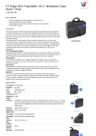
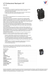
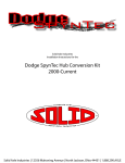
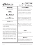
1
VW TYPE 2 MINI LOCKER
Updated 1/14/12
5255-INST
HOW THE MINI LOCKER FUNCTIONS
MINI LOCKER FEATURES
The Type 2 Mini Locker consists of two bi-directional over-running
dog clutches. Each one has a driving member (the driver) and a driven member (the existing sidegear). Both clutches are rotated by the
differential cross shafts to form a fully locking combination when
engine torque is applied (see Figure 1).
The Mini Locker’s design is simple and rugged, with no Belleville
washers, clutch packs or cone clutches to break or wear out. It uses
stainless steel springs for excellent resistance to high temperatures
and fatigue. The drivers and couplers are made from high-carbon
steel and are heat-treated for toughness and durability. Because it
is “all gears”, it does not require special limited-slip differential
additives in the gear oil.
The Mini Locker provides differential action when cornering by
allowing the rear wheels to rotate at different speeds. Because the
outside wheel is “ground driven” faster than the inside wheel, the
dog clutch disengages, allowing the outside wheel to rotate freely;
power continues to be applied to the slower (inside) wheel. In low
traction situations, the Mini Locker will always deliver power to the
wheel with the most grip, with up to 100% of the engine’s torque
available to either wheel.
In contrast, a standard “open” differential always divides torque
equally between the wheels. With an open differential, if one wheel
slips and starts spinning with only a small amount of torque applied,
the same small amount of torque is sent to the wheel with traction.
In other words, one wheel spins and you don’t move forward.
The Mini Locker eliminates this problem. Power will always be
delivered to the wheel with the most traction, which helps you keep
moving forward instead of getting stuck.
Thrust
Washer
Sidegear
Driver
Stop Pins
&
Springs
VEHICLE OPERATION
The Mini Locker is recommended for off-highway use only. A vehicle equipped with a Mini Locker will have much more traction than
before. We suggest that you get used to its new capabilities slowly.
Take it to an off-road area in which several types of terrain are present and try each one carefully to see how well your “new” vehicle
performs. Only after becoming thoroughly familiar with its new
capabilities should you put it through its paces with serious offroading.
Remember, the Mini Locker will extend the capabilities of your
vehicle and let you get places more easily, but it doesn’t make up
for carelessness and inexperience. Whatever the driving conditions,
be careful and have fun!
CAUTION - BreAkINg A drIve Axle: A drive axle can break when it
Cross Shafts
&
Center Block
Stop Pins
&
Springs
Driver
Sidegear
Thrust
Washer
Figure 1. Mini Locker Exploded View
WEDDLE INDUSTRIES • 7200 HOLLISTER AVENUE, SUITE C, GOLETA, CA 93117 • PH: (805) 562-8600 • FAX: (805) 562-8661 • INFO @ WEDDLEINDUSTRIES.COM
© Copyright Weddle Industries. All Rights Reserved.
5255-INST
1-1
is under a lot of power. A locking differential can effectively deliver
double the power to an axle (100% vs. 50% for an open differential).
If an axle breaks, the wheel on the opposite side will still be powered
because of the torque transferring capability of the locking differential, and the vehicle will tend to turn quickly toward the side on which
the break occurred. Vehicle control will be affected by a broken axle
shaft and further damage can occur. Replace it as soon as possible!
GENERAL INSTALLATION NOTES
The VW Type 2 Mini Locker is designed to fit into a “4-spider” 091
differential housing only. If you have a 002 differential housing (standard in 1969-1975 model year VW Bus transaxles), you will need to
purchase a 1976 and later 091 4-spider diff housing, thrust washers,
bearings, sidescrew adjusters, final drive flanges, and a few other
parts before proceeding. Weddle Industries offers a complete 002 to
091 differential conversion kit at a very reasonable price.
For racing vehicles or vehicles that will be subject to extreme abuse,
we also recommend that you use a heavy duty differential cover
(such as Weddle Industries part # 5212) instead of the stock VW differential cover.
Installing a Mini Locker is a relatively simple operation. However,
some special tools and a basic understanding of the VW transaxle
assembly procedure is required to remove and re-install the differential housing. Therefore, we recommend that an experienced VW
mechanic or transaxle builder perform the installation. These
instructions assume that the person installing the Mini Locker has
the Bentley VW Service Manual for reference to transaxle and differential removal, torque values, settings, clearances, etc.
These installation instructions are provided to assist you or your
mechanic with the installation of your new Mini Locker. However,
the ultimate responsibility for the success of the Mini Locker installation and the subsequent proper operation of your vehicle rests
with you, the vehicle owner. Be sure to read and understand the
driving information above!
PRELIMINARY OPERATIONS
The transaxle must be out of the vehicle and the oil must be drained
before the differential can be removed. If the same differential housing, differential cover, bearings, and adjusters are to be re-used, it is
not necessary to change the ring and pinion settings. However, you
must remember to mark the sidescrew adjusters and the transaxle
case with witness marks before disassembly so that each adjuster
can be set back to the same position upon re-assembly (also: mark
the adjusters left and right to make sure that they go back on the
correct side). These marks are very important for correct re-assembly! Any uncertainty about the correct positioning of the adjusters
means that backlash and pre-load will have to be reset.
1. Remove the bell housing, input shaft, final drive flanges, and
sidescrew adjuster locks from the transaxle. Before removing the
sidescrew adjusters, be sure to mark them as outlined above.
2. Remove the differential section from the transaxle.
3. Remove the ring gear bolts and the ring gear. It may need to be
tapped off the housing with a brass drift or soft mallet.
4. Separate the differential cover from the diff housing by tapping
the end of the sidegear gently from side to side with a soft mallet.
5. Remove the cross shaft retaining pins.
6. Remove the cross shafts, spider gears, sidegears, all thrust washers, and the center block.
INSPECTION OF THE PARTS
These steps are important. If inspection shows that any of the following parts are not in excellent condition, they must be replaced.
Please note that the spider gears and their concave thrust washers
will be eliminated.
1. Thoroughly wash all the differential parts, then dry them.
2. The condition of the sidegears is very important to the proper
operation of your new Mini Locker. We recommend installing new
sidegears (which should have been included with your Mini Locker if
you purchased it from Weddle Industries). If you are going to re-use
your old sidegears, carefully check the teeth for pitting, cracking, or
excessive wear. Most importantly, make sure that the top edges of
the teeth (where the sidegear engages the Mini Locker driver) are
not excessively worn. For the Mini Locker to function properly, there
must be good square top edges on both sides of the teeth.
3. Inspect the sidegear thrust washers. They are important for the
correct positioning of the Mini Locker parts. If they are excessively
worn or are cracked, obtain new ones.
4. Inspect the differential housing and cover for any wear, cracks, or
similar damage. Also inspect the bearings to make sure that they are
in good condition and that they fit tightly on the differential housing
and cover. If the housing, cover, or bearings look bad, replace them.
However, if you do, remember that the ring and pinion backlash and
bearing pre-load will need to be reset using a dial indicator, as
described in the Bentley VW Service Manual.
INSTALLATION OF THE MINI LOCKER PARTS
Before beginning Mini Locker installation, study Figure 1 so that you
will be familiar with the terminology used to describe the various
parts that came with your Type 2 Mini Locker.
1. Before assembly, it is a good idea to coat the teeth of the
sidegears and both sides of the thrust washers with a light layer of
medium grease. Also place a little grease in each of the four holes in
each driver. The grease will help hold the springs and pins in place
during assembly and assist with functioning of the parts until the
gear oil circulates.
2. Place a thrust washer and the long sidegear in the diff housing
(Figure 2). At this point, it is easiest to clamp the protruding splines
of the long sidegear in the soft jaws of a vise so that the large end of
the differential housing is facing up and the sidegear is held firmly
seated in the housing. This will give you two free hands to complete
the rest of the assembly.
WEDDLE INDUSTRIES • 7200 HOLLISTER AVENUE, SUITE C, GOLETA, CA 93117 • PH: (805) 562-8600 • FAX: (805) 562-8661 • INFO @ WEDDLEINDUSTRIES.COM
© Copyright Weddle Industries. All Rights Reserved.
5255-INST
1-2
Figure 2. Place the long sidegear (with
thrust washer) into the housing.
Figure 3. Place a driver onto the
sidegear with teeth meshed.
3. Place a driver onto the sidegear in the housing with the teeth
meshed (Figure 3).
4. Place the center block into the center of the driver. Carefully tap
the long cross shaft through the housing and the center block (Figure
4). Be very careful not to let the long shaft become caught on the
driver or the center block as it comes through! Also, make sure you
keep the retaining pin hole in the long cross shaft lined up with the
hole in the housing. If the shaft is hard to insert, use a brass or plastic mallet to drive it in to avoid damaging the ends. If you have problems getting everything lined up, check to make sure that the
sidegear is all the way down in the housing.
5. Carefully drive the short shafts into the remaining two holes in the
housing and center block. Once all the shafts are in place, install the
cross shaft retaining pins.
6. Place a double spring assembly (a small spring inside a large
spring) into each oblong hole in the bottom driver and place a stop
pin into each of the two round holes (Figure 5). IMPORTANT! The
springs should be about flush with the surface of the driver and they
must sit all the way in the bottom center of the oblong holes.
7. Repeat step 6 with the second driver (the one that is not yet in the
housing). The grease placed in the holes earlier will help hold things
in place (Figure 6). Note: at this point, each driver should have two
stop pins and two double spring assemblies installed.
Figure 5. Place a double spring assembly into each oblong hole in the bottom
driver and a stop pin into each round
hole.
Figure 4. Tap the cross shaft through
the housing and the center block.
8. Turn the top driver over and hold it so that the stop pins line up
with the springs in the opposite driver. Carefully lower it until the
pins rest on the springs (Figure 7). Push it up and down to be
absolutely sure that all pins and springs are in place and are functioning properly. Proper operation of the parts at this point is very
important!
9. Place the short sidegear onto the top driver with the teeth
meshed, then place the thrust washer onto the sidegear (Figure 8).
10. Place the differential cover onto the housing (Figure 9). Line up
the bolt holes and tap it down until seated.
11. Heat the ring gear to about 200° F and tap it into place on the differential housing with a soft mallet. Make sure that the bolt holes in
the ring gear line up with those in the housing. This is easiest if dowel
studs are used to guide the ring gear into the proper position on its
way down. Once everything is correctly in place, torque the ring gear
bolts to 40 ft-lb in a criss-cross pattern to make sure everything pulls
up evenly. We strongly recommend that you use a high strength
thread locking compound (such as Loctite 272) to help prevent the
ring gear bolts from coming loose.
12. Inspect your work. Look for anything that is not correct. Turn the
sidegears by the splines to make sure that the drivers easily rotate
back and forth a short distance, stopping at the cross shafts.
Figure 6. Repeat step 6 with the other
driver. The grease placed in the holes
earlier will help hold everything in place.
Figure 7. Install the top driver so that
the pins in the top driver rest on the
springs in the bottom driver.
WEDDLE INDUSTRIES • 7200 HOLLISTER AVENUE, SUITE C, GOLETA, CA 93117 • PH: (805) 562-8600 • FAX: (805) 562-8661 • INFO @ WEDDLEINDUSTRIES.COM
© Copyright Weddle Industries. All Rights Reserved.
5255-INST
1-3
FINAL ASSEMBLY
1. Place the assembled differential back into the transaxle case. The
ring gear should be on the left hand side of the car.
2. Thread the input shaft and the mainshaft together until the two
shafts meet and then back off one spline. Slide the coupler all the
way onto the splines and install a new snap ring to hold it in place. If
the same bearings, main housing, differential cover, and adjusters
are being re-used, the ring and pinion backlash and pre-load should
not have to be reset. Install the adjusters on their correct sides and
screw them in to their original positions, as marked before disassembly. During the final positioning of the adjusters, the tightening
should become more difficult as pre-load is being applied to the
bearings. If any of the parts mentioned above have been replaced,
the ring and pinion backlash must be reset using the method outlined in the Bentley VW Service Manual.
3. Install the sidescrew adjuster locks and final drive flanges using
new snap rings. Install new oil seal plugs into the final drive flange
centers to prevent transaxle fluid from leaking into your CV joints
and contaminating the grease.
4. When all the above steps are completed, the ring and pinion backlash and pre-load should be unchanged and no further adjustments
will be needed. It is a good idea to rotate the ring gear one revolution to be sure that nothing is binding, then rock the ring gear back
and forth to see if the backlash appears to be close to the factory recommended setting of .15mm to .25mm (.006" to .010") . If you have
any doubt about the correct positioning of the ring gear, you must
check the backlash and pre-load with a dial indicator, as outlined in
the Bentley VW Service Manual.
5. Once you are confident everything has been put back together
correctly, replace the bell housing (using a new gasket) and tighten
the bell housing bolts (or nuts) to 18 ft-lb. Clean and re-install the
magnetic drain plug.
6. Add gear oil. Most standard GL-4 rated 90-weight gear oils are
adequate, but you or your transaxle builder may prefer a specific
brand of “high performance” transaxle lubricant.
Note: Sometimes we have
noticed that initially the
parts may not unlock easily
because they need to
become “broken in.” If this
occurs, jack up both tires
and rotate them a few
times to circulate the gear
oil. Lower one tire back
down to hold it and rock the
other one back and forth;
the free tire should soon
unlock. If it still does not do
so, your installation may
need to be rechecked.
Contact Weddle Industries
for assistance.
Figure 8. Place the short sidegear
with thrust washer onto the top
driver with the teeth meshed.
TIRE DIAMETERS
To help ensure a long life
for your new Type 2 Mini
Locker, tire diameters
should be as nearly equal as
possible, although an exact
match is not required.
Contrary to instructions
that you may have read Figure 9. Place the differential
elsewhere, DO NOT change cover onto the housing, making
inflation pressures to vary sure to line up the bolt holes.
the rolling radius of the
tires! This can be dangerous if one of the tires is underinflated, producing excess heat and making vehicle control more difficult. The
best way to equalize the rotation is to measure the circumferences
of all the tires, including the spare. Choose ones that are within
about 3/8-inch or less of each other if possible. If one tire is worn
much more than the other one, they both should be replaced for
safety reasons.
7. Re-install the transaxle in the vehicle.
TESTING THE COMPLETED INSTALLATION
Before you put the engine back in the vehicle you should test the
Mini Locker installation to make sure it is functioning properly. First,
make sure that the vehicle is adequately blocked so that it cannot
roll forward or backward. Put the transaxle in 1st gear and make sure
the parking brake is off. Leave one rear tire on the ground to hold it,
and jack the other one up until it can turn freely.
Rotate the transaxle input shaft in either direction until it stops, and
hold it there tightly. Rotate the free tire; if it tends to turn the input
shaft, rotate it in the opposite direction. The tire should rotate and
the Mini Locker should “click” as the wheel turns. Rotate the input
shaft in the other direction until it stops again and check the rotation
of the tire in the opposite direction. Repeat this test on the other
side of the vehicle.
WEDDLE INDUSTRIES • 7200 HOLLISTER AVENUE, SUITE C, GOLETA, CA 93117 • PH: (805) 562-8600 • FAX: (805) 562-8661 • INFO @ WEDDLEINDUSTRIES.COM
© Copyright Weddle Industries. All Rights Reserved.
5255-INST
1-4