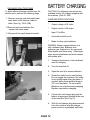
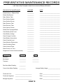
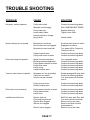
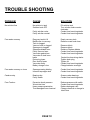
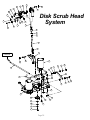
1
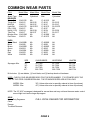
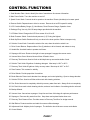
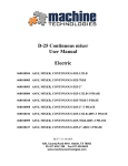
29ss SERIES
ACTORY CA
Operator, Parts, &
Service Manual
29", 33" Disk Scrubber
28", 32" Cylindrical
R.P.S. Corporation
P.O. Box 368
Racine, Wisconsin 53401
Phone: 1-800-634-4060
Fax:
1-866-901-3335
www.factorycat.com
Copyright R.P.S. Corporation 2003
Edition 1, World Rights Reserved.
29ss SERIES
Operator, Parts, &
Service Manual
29", 33" Disk Scrubber
28", 32" Cylindrical
Mid-Central Corporation
P.O. Box 241
Racine, Wisconsin 53401
Phone:
Fax:
1-800-450-9824
1-866-632-6961
www.tomcatequip.com
Copyright Mid-Central Corporation 2003
Edition 1, World Rights Reserved.
TABLE OF CONTENTS
OPERATING ILLUSTRATIONS
PARTS SECTION ILLUSTRATIONS
Table of Contents . . . . . . . . . . . . . . . . . . Page 1
Machine Delivery Form . . . . . . . . . . . . . Page 2
Machine Specifications . . . . . . . . . . . . . Page 3
Wear Parts . . . . . . . . . . . . . . . . . . . . . . . . . . Page 4
Safety . . . . . . . . . . . . . . . . . . . . . . . . . . . . . . Page 5-6
Machine Controls . . . . . . . . . . . . . . . . . . . Page 7-8
Machine Prep & Operation . . . . . . . . . . . Page 9-14
Machine Maintenance & Storage . . . . Page 15
Preventative Maintenance . . . . . . . . . . . Page 16
Troubleshooting Guide . . . . . . . . . . . . . . Page 17-18
Solution System . . . . . . . . . . . . . . . .
Recovery System . . . . . . . . . . . . . . .
Body Parts . . . . . . . . . . . . . . . . . . . . . .
Jaw Assembly . . . . . . . . . . . . . . . . . . .
Traction Drive . . . . . . . . . . . . . . . . . . .
Squeegee System . . . . . . . . . . . . . . .
Central Command II . . . . . . . . . . . . . .
Squeegee Lift (Optional) . . . . . . . . . . .
Water Jet System . . . . . . . . . . . . . . . . .
Disk Scrub Head System . . . . . . . . .
Cylindrical Deck . . . . . . . . . . . . . . . . . .
Cylindrical Mechanical . . . . . . . . . . . .
Page 20-21
Page 22-23
Page 24-25
Page 26-27
Page 28-29
Page 30-31
Page 32-33
Page 34-35
Page 36-37
Page 38-39
Page 40-41
Page 42-43
MACHINE INFORMATION
Please fill out at the time of installation and store in a safe place for future reference.
Model Number:____________________________________________________________________
Serial Number____________________________________________________________________
Installation Date:___________________________________________________________________
DEALER INFORMATION
Installing Dealer:___________________________________________________________________
Dealer Contact:____________________________________________________________________
Address:_________________________________________________________________________
City, State, & Zip:___________________________________________________________________
Phone Number:____________________________________________________________________
This Operator, Parts, and Service Manual should be considered a permanent part of the unit,
and should remain with the unit at all times. You may find descriptions and features that are
not on your particular model. The information and specifications included in this publication
were in effect at the time of printing. The manufacturer reserves the right to make changes
without notice and without incurring any obligation.
TO REGISTER FOR WARRANTY, FAX YOUR DELIVERY FORM TODAY!
PAGE 1
MACHINE DELIVERY FORM
Dealer: ________________________________________________
Serial Number:___________________
Location: (City, ST): ______________________________________
Install Date: _____________________
Hour Meter: _____________________
Customer: _____________________________________________
Installed By: _____________________
Contact: _______________________________________________
Address: _______________________________________________
City: ____________________ State: _________ Zip: ____________
Phone: ____________________ Fax: _______________________
Model Number: _____________________________
Options:
1. __________________________
2. _____________________________
3. __________________________
4. _____________________________
5. __________________________
6. _____________________________
Brushes: __________________________________
Broom: __________________________________
Soap: _____________________________________
Buyer's Representative Has:
1.
2.
3.
Received instruction in proper operation of this machine.
Received operator's manual for this machine.
Been made aware that any operator read the manual
before operating this machine.
Dealer Rep.: (Print) ____________________________
(Sign) _____________________________________
Customer:
(Sign) _____________________________________
(Print) ____________________________
PAGE 2
SPECIFICATIONS
29ss
35ss
BODY CONSTRUCTION/DIMENSIONS
Tank Construction:
Frame Construction:
Drive Wheel:
Casters:
Height:
Length:
Width (body):
Width (squeegee):
Weight (w/out batteries):
Weight (w/ batteries):
(7/16 ) Roto-Poly
3/16 (Stainless Steel)
(2) 11 diameter x 4
(2) 6 Diameter x 2
43 inches
57 inches
30 inches
32 , 35 or 38
766 pounds
1,246 pounds
(7/16 ) Roto-poly
3/16 (Stainless Steel)
(2) 11 diameter x 4
(2) 6 Diameter x 2
43 inches
59 inches
35 inches
38 or 45
786 pounds
1,266 pounds
BRUSH/PAD SYSTEM
Brush/Pad Diameter (Disk):
Motor (Disk):
Brush Pressure (Disk):
(2) 15.5 inches
(2) 1.0 hp / 350 rpm
0-300 pounds
(2) 17.0 inches
(2) 1.0 hp / 350 rpm
0-300 pounds
Brush Size (Cylindrical):
Motor (Cylindrical):
Brush Pressure:
(2) 28 long x 5.5
(1) 2.0 hp / 800 rpm
0-250 pounds
(2) 32 long x 5.5
(1) 2.0 hp / 800 rpm
0-250 pounds
BATTERY SYSTEM
Battery AH Rating:
Battery description:
Battery Run Time:
Charger (110v):
396 amp hour
6-volt deep cycle
Up to 5 hours
36 amp automatic
396 amp hour
6-volt deep cycle
Up to 5 hours
36 amp automatic
SOLUTION SYSTEM
Solution Tank Capacity:
Solution Flow Rate:
30 gallons
Up to .75 gal/min.
30 gallons
Up to .75 gal/min.
RECOVERY SYSTEM
Recovery Tank Capacity:
Vacuum Horsepower:
Water Lift:
Airflow (Cubic Feet / Minute):
30 gallons
1.0 hp, 3-stage
70 inches
72 cfm
30 gallons
1.0 hp, 3-stage
70 inches
72 cfm
DRIVE SYSTEM
Transaxle Description:
Speed Control:
.75 hp, Differential
Variable 0-275 ft/min
.75 hp, Differential
Variable 0-275 ft/min
Disk - 29 Inches
Cylindrical 28 Inches
Disk - 33 Inches
Cylindrical 32 Inches
35,640 sq. ft/hour
43,560 sq. ft./hour
PRODUCTIVITY
Cleaning Width:
Cleaning Rate/Hour
(W/2 Overlap)
AUTHORIZED DISTRIBUTOR
PAGE 3
COMMON WEAR PARTS
ITEM
Model 29ss
Model 29ss
Model 35ss
Model 35ss
Brush Type
BRUSHES
Super-Grit
Tough-Grit
Midi-Grit
Light-Grit
Poly (.028)
Nylon (.012)
Tam Pico
Butcher Wire
Pad Driver
Disk
Cylindrical
Disk
Cylindrical
15-421SS
15-421S
15-421C
15-421PS
15-421P
15-421N
15-421T
15-421BW
15-421D
NA
28-521S
28-521C
28-521PS
NA
28-521N
28-521T
NA
NA
17-421SS
17-421S
17-421C
17-421PS
17-421P
17-421N
17-421T
17-421BW
17-421PD
NA
32-521S
32-521C
32-521PS
NA
32-521N
32-521T
NA
NA
PADS
Super Black
Black
Brown
Green
Blue
Red
White
15-422BB
15-422B
15-422BR
15-422G
15-422BL
15-422R
15-422W
NA
NA
NA
NA
NA
NA
NA
17-422BB
17-422B
17-422BR
17-422G
17-422BL
17-422R
17-422W
NA
NA
NA
NA
NA
NA
NA
Squeegee Kits:
SIZE
32":
35":
38":
45":
GUM RUBBER
22-770G
25-770G
28-770G
290-770G
NEOPRENE
22-770N
25-770N
28-770N
290-770N
LINATEX
22-770L
25-770L
28-770L
290-770L
Kit Includes: (2) rear blades, (1) front blade, and (2) backup wheels w/ hardware
NOTE: CHECK YOUR SQUEEGEE BODY FOR THE SIZE NUMBER. IT IS STAMPED INTO THE
TOP OF THE STEEL SQUEEGEE BLANK. THE STANDARD SIZES ARE AS FOLLOWS:
MODEL 29ss
MODEL 35ss
38" (Unless other size is specially ordered at time of purchase)
45" (Unless other size is specially ordered at time of purchase)
NOTE: The 32" & 35" squeegee is designed for narrow isles and may not have the same water control
around tight turns as the larger squeegees.
SOAP
Heavy Duty Degreaser
Citrus
Freezer
Tire Mark Remover
CALL LOCAL DEALER FOR INFORMATION
PAGE 4
!! SAFETY MESSAGES !!
Your safety, and the safety of others, is very important, and operating this unit
safely is an important responsibility.
To help you make informed decisions about safety, we have provided
operating procedures and other safety information in the manual. This
information informs you of potential hazards that could hurt you or others.
It is not practical or possible to warn you of all the hazards associated with
operating this unit. You must use your own good judgment.
This unit is intended for commercial use. It is designed to clean hard floors in an
indoor environment, with the recommended pads/ brushes, and cleaning
solutions.
1. DO NOT OPERATE UNIT:
*
Unless trained and authorized.
*
Unless operator manual is read, and understood.
*
If unit is not in proper condition.
2. WHEN OPERATING UNIT:
*
Remove loose objects from the floor that may be
projected from the revolving brushes.
*
Keep hands and feet away from revolving brushes and
brooms.
*
Do not run machine where flammable liquids are present.
*
Use extreme caution when maneuvering.
3. BEFORE LEAVING:
*
Make sure machine is turned off.
*
Stop on level surfaces.
*
Disconnect batteries.
4. BEFORE SERVICING:
*
Stop on level surfaces, and secure machine.
*
Disconnect batteries.
PAGE 5
!! SAFETY PRECAUTIONS !!
WARNING:
Hazardous voltage. Shock or
electrocution can result. Always disconnect
the batteries before servicing this machine.
WARNING: Always use the charger provided
WARNING: Batteries emit hydrogen gases,
by the manufacturer to charge the machine.
It is an automatic charger, specifically
designed to charge at the appropriate rate. If
you must use a different charger, disconnect
the
batteries before charging. This will
prevent damage to the electronic speed
controller.
explosion or fire can result. Keep sparks and
open flames away.
Charge unit only in a wellventilated
area,
and
keep
battery
compartment open when charging. Explosion
or fire could result.
WARNING:
Battery acid can cause burns.
Wear protective eyewear and gloves when
servicing batteries.
WARNING:
Understand
the
dynamic
braking system before you operate the
machine on slick ramps. Machine does not
coast. Releasing the handlebar "green" drive
buttons, will automatically apply braking force,
and stop the machine.
WARNING:
Do not park the machine on
ramps or slopes. This machine does not
have a parking brake. It must always be
parked on level ground.
WARNING:
WARNING:
Do not store
pressure wash.
Prevent
electronic components wet.
outdoors or
from getting
WARNING:
The use of parts and solutions
other than recommended by the manufacturer
may cause damage.
Do not operate the machine if
any parts have been removed or damaged.
WARNING:
WARNING: Do not remove, paint over, or
WARNING: Dress Safely. Do not wear rings
or metal wristwatches while working on this
machine. They can cause an electrical short,
which can cause serious burns. Do not work
on this machine while wearing a tie, scarf or
other loose, dangling neckwear or clothing.
These loose items can tangle in the rotating
parts and cause serious injury or even death.
WARNING: Do not use the machine as a step
destroy Warning Decals. If Warning Decals
become damaged, they must be replaced.
Do not operate machine in
unsafe condition. If the machine is in need of
repair or is in any way unsafe to operate, the
matter should be reported immediately to the
shift supervisor. Do not operate the machine
until it is returned to proper operating
condition.
WARNING:
ladder or chair.
This machine must only be
operated by a trained operator. As part of his
or her training, they must read this manual
thoroughly.
If extra copies are needed
contact your local dealer.
WARNING:
WARNING: Do not ride on this machine.
It
was not designed to carry passengers.
WARNING: Do not operate this machine on
ramps or uneven surfaces. When climbing a
ramp, always drive the machine in forward
straight up or down the ramp. Never drive
across the incline. DO NOT BACK DOWN
RAMPS!
WARNING: Always
turn off the machine
before leaving it unattended.
WARNING: Do not operate this scrubber over
floor outlets. SEVERE INJURY!
WARNING: Do not use machine to apply or
pick up flammable liquids. Fire or Explosion
Hazard!
PAGE 6
CONTROL FUNCTIONS
1. Serial Number Plate: Used to identify the date of manufacture & customer information.
2. Main Power Switch: Turns the machine on and off.
3. Speed Control Knob: Controls the drive speed on the machine. Rotate (clockwise) to increase speed.
4. Reverse Switch: Depress down to drive in reverse. Reverse is set at 50% speed for safety.
5. LCD: Contains Battery Gauge, (3) Hour Meters, Down Pressure Gauge, Operation Icons.
6. Recharge Plug: Use only 24-V/36-amp charger provided with the machine.
7. LCD Menu Select: Changes the LCD from screen #1 to #2 or #3.
8. Brush Pressure Switch: Controls brush pressure (1-5) 5 being the highest.
9. Brush Up/Down Switch: Brushes will only run when in the down position. Raise to transport only.
10. Solution Control Knob: Controls the solution flow rate, when the solution switch is on.
11. Drive Control Buttons: Depress either of the (2) switches to drive forward, and release to stop.
12. Handle Bar: Use both hands to operate at all times.
13. Squeegee Lift Lever: Rotate to the right to lower squeegee & engage the vacuum motor.
14. Vacuum Motor Cover: Mounts Vacuum Motor & Seals to hose.
15. Recovery Tank Access: Used to flush out buildup that may accumulate inside of tank.
16. Solution Tank: Holds 30 gallons of cleaning detergent. Max temp is 140 F or 60 C.
17. Recovery Tank: Holds 30 gallons of dirty recovery water. Max temp is 140 F or 60 C.
18. Rear Casters: Twin casters for stability.
19. Drive Wheels: Provide propulsion for machine.
20. Brush Shrouds: Protect scrub brushes from damage, and control splashing. Open to change brushes.
21. Solution Fill Door: Used to refill the solution tank with cleaning solutions.
22. Rec. Drain Hose used to completely drain dirty recovery water from tank. Always flush out completely.
23. Sol. Drain Hose used to drain cleaning solution, and as a level indicator of remaining solution onboard.
24. Backup Wheels.
25. Vacuum Hose: Vacuumizes squeegee. Keep free and clear of blockage for optimum performance.
26. Squeegee: Recovers dirty water from floor. Keep clean and replace blades when worn.
27. Recovery Tank Cleanout Door: Provides access to Recovery Tank floor for sludge removal.
28. Wall Rollers: Protects machine and walls from some collision damage.
29. Adjustment Knob: Adjusts pitch of squeegee. The deflection should be even across entire blade.
30. Corner Wheels.
PAGE 7
MACHINE CONTROLS AND FEATURES
8
7
3
9
10
13
1
6
12
2
4
5
11
1.
2.
3.
4.
5.
6.
7.
8.
9.
10.
Serial Number Plate
Main Power Switch
Speed Control Knob
Reverse Switch
LCD (Guages & Meters)
Recharge Plug
LCD Menu Select
Brush Pressure Switch
Brush On/Off Switch +/Solution Control Knob
11.
12.
13.
14.
15.
16.
17.
18.
19.
20.
Drive Buttons
Handle Bar
Squeegee Lift Lever
Vacuum Motor Cover
Recovery Tank Access
Solution Tank
Recovery Tank
Rear Casters
Drive Wheels
Brush Guards
21. Solution Fill Door
22. Rec. Drain Hose
23. Sol. Drain Hose/Sight Tube
24. Backup Wheels
25. Squeegee Hose
26. Squeegee
27. Rec. Tank Cleanout Door
28. Wall Rollers
29. Squeegee Knob
30. Corner Wheels
15
22
21
17
14
16
23
25
27
26
PAGE 8
24
29
18
30
19
20
28
MACHINE PREP
MACHINE SETUP
UNCRATING MACHINE
ATTACHING SQUEEGEE
Carefully check the crate for any signs of
damage. Check the crate to ensure that all
accessories are included. Batteries are in
the unit. The squeegee, brushes, and other
items are in the crate.
1.
Lower the squeegee mounting plate by
releasing the lever. (See Fig. 2)
To uncrate the machine, remove banding
from around the crate. Take off the top and
sides and dispose of properly. Remove
banding from machine. Remove the chocks
around the drive wheels. Fold down ramp,
and roll machine off of the base.
NOTIFY THE CARRIER IMMEDIATELY IF
CONCEALED DAMAGE IS DISCOVERED.
Fig. 2
CONNECTING BATTERIES
2.
Loosen the two wingnuts on the
squeegee and slide them into the slots
in the squeegee mounting plate. The
squeegee trail wheels should face
outward.
3.
Tighten the two wingnuts, and connect
vacuum hose from the machine to the
squeegee. (See Fig. 3)
4.
You may need to adjust the squeegee
pitch, by using the pitch adjustment
knob.
Your machine is equipped with (4) 6 volt,
deep cycle, 395 amp hour batteries, which
form a 24 volt system.
1. Turn all switches to the OFF position.
2. Hinge open the rear compartment lid
to access the batteries.
3. All four cables should be tightly connected
to the batteries. Locate any loose one's
and tighten. This require's a 9/16" wrench.
Do not leave connection loose. Loose
connections burn cable. (See Fig. 1)
4. Turn on main power switch and check the
battery condition meter to ensure correct
installation. Charge batteries if needed.
(See BATTERY CHARGING)
Fig. 3
Fig. 1
PAGE 9
WARNING:
TURN OFF MACHINE BEFORE INSTALLING BRUSHES.
INSTALLING DISK BRUSH OR PAD
INSTALLING CYLINDRICAL BRUSH
1. Raise scrub head. Turn the machine on
and press the bottom half of the brush
up/down on/off switch (o).
1. Unscrew the three wingnuts on the brush
access door and remove the door. Be
careful not to lose the wingnuts and lock
washers. (See Fig. 7)
2. Pull pin on channel & open brush guards
to access the drivers. (See Fig. 4)
Fig. 4
3. Select the correct pads or brushes that
best meet your cleaning application.
Consult your local dealer for assistance.
(See Fig. 5 on page 12)
4. PAD INSTALLATION Attach pads to pad
drivers before connecting drivers to motor
hub. Remove the centerlock ring from the
pad driver and position the pad on the pad
driver, and replace the center locking ring.
Fig. 7
2. Slide the brushes in, one at a time. When
you get the brush on the driver, spin it with
your hand until you feel it catch and drop
in. When both brushes are in, replace the
door and the fasteners. (See Fig. 8)
5. Attach brushes or pads to motor hubs.
Squeeze the scissor locking device and lift
brush up on to the motor drive hub. Make
sure the scissors close and lock once the
brushes are on. (See Fig. 6)
Fig. 8
Fig. 6
6. Close the brush shrouds and tighten the
wingnuts on either side.
PAGE 10
NOTE: IF BRUSHES ARE NOT FULLY
ENGAGED WITH THE DRIVERS. THE
BRUSHES WILL BE DAMAGED. DO
NOT FORCE THE ACCESS DOOR
BACK ON. THIS USUALLY INDICATES
IMPROPER INSTALLATION.
FILLING SOLUTION TANK
ONE PASS SCRUBBING
1. Transport the machine to the filling
station. Raise the scrub head and
squeegee when transporting.
STEPS: (See Fig. 10)
2. Turn machine off.
3. Open front lid at the front of the
machine and unscrew clear solution
lid to fill the tank with up to 30 gallons
of clean water. The clear tube at the
rear of the machine indicates the
amount of water in the tank.
(See Fig.9)
4. Add cleaning chemical. Use the
proper dilution ratio indicated on the
bottle. A proportioning system is
preferred.
*Use only nonflammable commercial
cleaning chemicals. If you need
assistance in selecting a proper
chemical call 1-800-634-4060.
1. Turn machine on, make sure the
speed knob is at a low setting.
2. Lower squeegee by moving the lift
lever all the way to the right.
3. Set brush pressure using Black
Toggle (#1). Start on #1 or #2.
4. Lower scrub head to the floor using
Black Rocker (#2).
5. Adjust the solution control knob to
the desired setting (#3).
6. Begin scrubbing by holding the green
drive buttons. Adjust the speed
control knob to the desired setting.
7. To operate machine in reverse,
simply pull the reverse switch back
towards the handlebar. Do not push
green buttons when reversing.
8. To stop the machine, let go of the
green control buttons or reverse
switch.
1 2 3
Fig. 9
OPERATION
Read and understand the safety section on
Page 6 & 7 before operating machine.
PRE-CLEANING CHECK LIST
*
Check battery condition gauge to
make sure batteries are fully charged.
*
Check condition of pads or brushes.
*
Check condition of squeegee blades.
Fig. 10
PAGE 11
OPERATING HINTS
1. Observe the amount of solution the machine is dispensing on the floor and adjust to the desired flow. To
increase the solution flow rate, rotate the solution control knob clockwise. To shut the solution off
completely just release the drive buttons. Solution stops when brushes stop.
2. Keep an eye on foam buildup in the recovery tank. If excess foam begins to develop, pour a
recommended foam control solution into the recovery tank. Foam is usually an indication of excessive
soap, so a better answer may be to use less chemical.
3. Always operate at lower speeds when scrubbing around walls and objects. You should also reduce the
speed to maintain control when turning.
4. If the squeegee starts to streak, raise and wipe the blades with a clean cloth. If the problem continues,
check the blades for wear or damage, and rotate if needed. You need to presweep before scrubbing if
you are using a disk machine. Alway's be sure to check the squeegee hose for clog's at the recovery tank
elbow.
5. Change or turn over pads when dirty. Rotate the scrub brushes every week.
6. Stay clear of objects protruding from the floor, such as sockets, grates, pipes, for they will damage the
pads and squeegee blades, or create dangerous situations.
7. During brief stops, you do not have to turn anything off. The brushes and solution will automatically stop
when the green control buttons are released.
8. Always keep an eye on your LCD window. They are there to help you scrub more efficiently, by letting
you know the status of that particular system at a glance. If the battery gauge is reading low, you must
stop immediately and recharge. Running the battery dead will result in damage to the battery.
9. When you run out of solution, raise the brushes, and continue to vacuum the remaining water until it is
consumed. The solution drain hose is also used to indicate the level of detergent remaining in the tank.
10. When you are ready to stop, pick up the brushes, turn off the solution switch, pick up the squeegee, and
drive the machine back to the charging area. Be sure to drain both tanks before storing machine for an
extended period of time.
Fig. 5
BRUSH TYPE
Super-Grit
Tough-Grit
Midi-Grit
Light-Grit
Poly (.028)
Nylon (.012)
Tampico
Pad Driver
DISK
##-421SS
##-421S
##-421C
##-421PS
##-421P
##-421N
##-421T
##-421D
CYLINDRICAL
NA
##-521S
##-521C
##-521PS
NA
##-521N
##-521T
NA
LEVEL (10 The highest)
Very High
10
High
9
High
8
Moderate
6
Moderate
5
Light
2
Light
1
Not Applicable
COLOR
Red/Orange
Black
Blue/Grey
Grey
Black
White
Tan
NA
PADS
Super Black
Black
Brown
Green
Blue
Red
White
DISK
##-422BB
##-422B
##-422BR
##-422G
##-422BL
##-422R
##-422W
CYLINDRICAL
NA
NA
NA
NA
NA
NA
NA
LEVEL (10 The highest)
Very High
10
High
8
High
7
Medium
6
Moderate
4
Moderate
3
Light
1
COLOR
Black
Black
Brown
Green
Blue
Red
White
NOTE:
These are only approximations.
The customer should always try any brush in an inconspicuous area.
PAGE 12
DRAINING TANKS
DRAINING RECOVERY TANK
Alway's empty recovery tank when
refilling the solution tank. To drain the
recovery tank, perform the follwing steps.
1. Remove drain hose from the expansion
plug holder by turning the T-Handle
counter clockwise, lower to drain.
(See Fig.11A & 11B)
Fig. 11B
Fig. 11A
2. Rinse the recovery tank after every use.
This will prevent heavy buildup on the
bottom of the tank, foul odors, and clogging
of the drain hose. (See Fig. 11C)
3. Once tank is empty, put drain hose back on
the plug and tighten by turning clockwise.
4. You may use the cleanout port for sludge
removal. (See Fig. 11D)
Fig. 11D
Fig. 11C
PAGE 13
DRAINING SOLUTION TANK
To drain leftover cleaning solution from the
solution tank, perform the following steps.
1. Remove end cap and clear sight tube/
drain hose off the bracket, lower to
drain. (See Fig. 12A & 12B)
2.Rinse out tank and solution flow
system with clean water.
3. Reconnect the cap & hose to bracket.
BATTERY CHARGING
CAUTION: The following instructions are
intended for the 24V charger supplied with
the machine. (Part # 7-244)
CHARGER SPECIFICATIONS
*
Output voltage of 24 Volts.
*
Output current of 36 Amps.
*
Input 110v/60hz
*
Automatic shutoff circuit.
*
Made for deep cycle batteries.
DANGER: Always charge batteries in a
well ventilated area. Batteries emit
hydrogen gas. Explosion or fire can result.
Keep sparks and flame away. Shield eyes
when servicing batteries and avoid contact
with battery acid.
Fig. 12A
1.
Transport machine to a well ventilated
area for charging.
2.
Turn the machine off.
3.
Open the rear lid to access batteries.
4.
Check the water level in each battery.
Do not charge the machine if the water
is not slightly higher than the plates. If
needed, add enough distilled water to
3/4" over the plates. Do not overfill!
Batteries can overflow during charging.
Replace caps before charging.
5.
Connect the red charger plug into the
battery charging port located at the rear
of the machine. (See Fig.12)
6.
With the red charger plug disconnected
from the machine, plug the charger
power cord into a grounded wall outlet.
Fig. 12B
PAGE 14
5. Wipe down machine if needed. Use a
non-abrasive, non-solvent cleaner, or a
clean damp cloth.
6. Recharge the batteries if needed.
WEEKLY MAINTENANCE
Fig. 12
7.
The charger will automatically begin
charging, and automatically shut off when
fully charged. (See charger gauge)
8.
After the charger has turned off, unplug
the red plug from the machine and
disconnect charger from the wall outlet.
9.
Recheck the cell levels after charging. If
needed, add distilled water up to the
correct level. Be certain to replace the
caps securely and to wipe off the top of
the batteries with a clean cloth. Discard
cloth.
MAINTENANCE
FILL BATTERIES APPROXIMATELY
3/4" TO 1" ABOVE THE LEAD PLATES.
OVERFILLING WILL CAUSE THE
BATTERIES TO LEAK DURING
CHARGING. THE CHARGING
PROCESS CREATES GAS BUBBLES
INSIDE THE BATTERY. WHICH
EFFECTIVELY INCREASES THE
VOLUME OF THE ELECTROLITE.
2. Clean battery tops to prevent corrosion.
3. Rotate brushes. Rotate the left to right
and right to left. On cylindrical models
from front to back.
MONTHLY MAINTENANCE
DAILY MAINTENANCE
1.
1. Check water level in each cell of the
batteries, and fill as needed. Always use
distilled water to refill batteries. Batteries
SHOULD NOT be filled to the tops of the
caps.
1. Lubricate rear casters with a waterproof
grease.
Remove and clean pads or brushes.
Never use soiled pads when cleaning.
Replace pads frequently.
2. Check machine for water leaks and
loose nuts and bolts.
Remove and clean debris from the float
shut-off screen located inside the
recovery tank.
STORING MACHINE
3.
Drain and rinse tanks thoroughly. Inspect
vacuum hose for any objects obstructing
the air flow.
1. Be sure to flush the tanks out
completely, and to drain all water from
the machine.
4.
Raise squeege and wipe blades with a
clean cloth. Store squeegee in the raised
position to prevent damage or settling of
the blades.
2. Remove the recovery tank lid to promote
air circulation.
2.
3. Raise brushes and squeegee.
PAGE 15
PREVENTATIVE MAINTENANCE RECORDS
USE THIS FORM TO MAKE COPIES FOR YOUR INTERNAL RECORDS
PREVENTATIVE MAINTENANCE
CHECKED
NOTE
Rotate Brushes / Replace Pads
__________
________________________________
Rotate Side Brooms
__________
________________________________
Drain Solution Tank
__________
________________________________
Flush Solution System
__________
________________________________
Clean Solution Screen
__________
________________________________
Drain Recovery Tank
__________
________________________________
Flush Recovery Tank
__________
________________________________
Clean Vacuum Screen
__________
________________________________
Rotate Rear Squeegee Blade
__________
________________________________
Check Battery Water Level
__________
________________________________
Check Battery Voltage
__________
________________________________
Check Charger Condition
__________
________________________________
Check Battery Connections
__________
________________________________
Check Chemical Level
__________
________________________________
Check Machine Performance
__________
________________________________
Check Scrubbing Power
__________
________________________________
Check Vacuum Power
__________
________________________________
Water Control on Turns
__________
________________________________
Gauges and Controls function smoothly
__________
________________________________
HOUR METER
CURRENT
LAST
Keyswitch:
__________
__________
Brushhead:
__________
__________
Transport:
__________
__________
Past Hour Meter Reading:
__________
Current Hour Meter Reading:
__________
Average Weekly Usage: ___________________
Technician Print:
__________________________
Date: ___________________________
Technician Signature:
__________________________
Date: ___________________________
Manager Signature:
__________________________
Date: ___________________________
PAGE 16
TROUBLE SHOOTING
PROBLEM
CAUSE
SOLUTION
No power, nothing operates
Faulty main switch
Contact local servicing dealer
Batteries need charging
See CHARGING BATTERIES
Faulty battery(s)
Loose battery cable
Replace battery(s)
Tighten loose cable
Interrupt switch on charger
plug is stuck
Unstick switch
Brush deck is not down
Put brush deck down w/ switch
Drive buttons are not engaged
Engage drive buttons
Brush deck current overload
Turn power off for 5 second s
Carbon brushes worn
Faulty brush motor or wires
Then turn back on
Contact local servicing dealer
Contact local servicing dealer
Drive motor does not operate
Speed control turned down
Recharge switch misadjusted
Faulty speed controller or wires
Faulty drive motor
Faulty wiring
Carbon brushes worn
Turn up speed control
Contact local servicing dealer
Contact local servicing dealer
Contact local servicing dealer
Contact local servicing dealer
Contact local servicing dealer
Vacuum motor does not operate
Squeegee is in the up position
Faulty vacuum switch
Vacuum current overload
Rotate squeegee lift lever down
Contact local servicing dealer
Turn main power off and then
turn on
Faulty vacuum motor
Carbon brushes worn
Contact local servicing dealer
Contact local servicing dealer
Drive motor runs incorrectly
Faulty speed controller or wires
Faulty potentiometer
Loose wires
Contact local servicing dealer
Contact local servicing dealer
Contact local servicing dealer
Insufficient solution flow
Solution tank low
Flow knob turned down
Solution filter clogged
Solution line clogged
Refill Sol. tank, drain Rec. tank
Turn knob counter-clockwise
Remove cover and clean
Remove and blow out with
compressed air
Remove cover and clean
Brush motor(s) do not operate
Solution valve clogged
PAGE 17
TROUBLE SHOOTING
PROBLEM
CAUSE
SOLUTION
No solution flow
No solution in tank
Solution knob OFF
Fill solution tank
Turn solution knob counterclockwise
Contact local servicing dealer
Contact local servicing dealer
Faulty solution valve
Faulty solution reostat
Poor water recovery
Recovery tank is full
Ball/Screen in recovery
Tank is clogged
Vacuum hose is clogged
Squeegee is clogged
Squeegee blades worn
Faulty vacuum hose
Vac motor gasket torn
Vac motor to tank hose
leaks
Drain plug loose
Rec. tank lid loose
Vac motor faulty
Battery charge is low
Contact local servicing dealer
Tighten drain plug
Tighten lid
Contact local servicing dealer
Charge batteries overnight
Poor water recovery on turns
Squeegee swing binding
Incorrect squeegee size
Contact local servicing dealer
Contact local servicing dealer
Casters noisy
Bearings dry
Faulty caster
Grease caster bearings
Contact local servicing dealer
Poor Traction
Excessive brush pressure
Worn drive tires
Heavy soap concentration
Tires damaged from chemical
Reduce pressure with switch
Contact local servicing dealer
Reduce detergent ratio
Change chemical or change to
black tires
PAGE 18
Empty recovery tank
Remove screen and clean
Remove debris
Remove debris
Rotate or Replace blades
Contact local servicing dealer
Contact local servicing dealer
SPARE PARTS BOOK
Walk-Behind Scrubbers
Spare parts are sold through authorized Dealers. If you have forgotten your dealer's name,
or you have moved the machine to a new location, please Call us at: 1 (800) 634-4060, or
Fax us at: 1 (866) 901-3335 and we will re-establish a dealer contact for you.
TO ORDER PARTS:
Please provide the machine's Serial No. with your order. Normally, ordinary parts orders
are shipped out the same day the order is received.
EMERGENCY ORDERS:
Within the Continental United States, We can supply any part that weighs under 70lbs
within 3 business days, not counting weekends or National Holidays.
However, if parts are ordered on an "Emergency" basis, this means that we will ship them
by fastest means, generally by air courier service, at the customers expense.
FREIGHT:
Within the United States, the normal shipment method is by customer choice, while the
emergency shipment method is by R.P.S. choice - normally by fastest means. This
means that emergency orders will generally cost the customer more than normal orders.
In both cases, the customer is responsible for all freight costs.
PAGE 19
Model 29ss/35ss
Parts Breakdown
Solution System
2
13
15
12
19
11
18
CLEANOUT DOOR W/GASKET
(FITS BOTH TANKS)
PN 7-415
10
TANK SCREW ON LID WITH GASKET & SCREWS
PN 7-425
5
19
2
17
SOLUTION LEVEL SIGHT TUBE AND
DRAIN HOSE 1" ID WITH HOSE CAP & END BARB
PN 7-417
14
18
12
11
1
15
10
13
9
3
5
25
4
8
8
16
21
23
8
8
24
26
22
6
8
20
Page 20
7
Solution System
Item
1
2
3
4
5
6
7
8
9
10
11
12
13
14
15
16
17
18
19
20
21
22
23
24
25
26
Part No.
Part Desription
Comments
Qty
7-414
SOLUTION TANK
1
PN 7-425 INCLUDES ITEMS 2,18,19
7-425
TANK SCREW ON LID W/GASKET
1
7-414A
BULKHEAD FITTING, 3/4" FNPT
1
7-454
3/4 NPT TO 5/8 STRAIGHT BARB
1
PN 7-417 INCLUDES ITEMS 5, 10, 11, 12 1
H-62005
CLAMP 5/8 - 1 1/2" SS
7-112C
1.0 OD X .50 GROMMET
2
21-4500
ADJUSTABLE SOLUTION FLOW VALVE
1
21-1612
HOSE CLAMP 1/2" - 29/32"
5
7-430
1-1/2" MNPT TO 1" BARB
1
7-417A SOLUTION LEVEL SIGHT & DRAIN HOSE 1" ID PN 7-417 INCLUDES ITEMS 5, 10, 11, 12 1
PN 7-417 INCLUDES ITEMS 5, 10, 11, 12 1
7-418
1" NPT TO 1" BARB
PN 7-417 INCLUDES ITEMS 5, 10, 11, 12 1
7-418A
1" FNPT PIPE CAP
7-415A
CLEANOUT DOOR
1
PN 7-415 INCLUDES ITEMS 13 & 15
5-728
DETERGENT WARNING PLATE
1
PN 7-415 INCLUDES ITEMS 13 & 15
7-416
CLEANOUT DOOR GASKET
1
5-913
INLINE FILTER
1
H-72904
PPH SMS #6 X 1/2" SS
4
38-742
SCREW ON LID GASKET
1
H-72916
PPH SMS #8 X 3/4" SS
6
H-73747
RPH #10-32 X 1 1/4" SS
2
H-70858
NYLOK #10-32 SS
2
H-72565
RPH #10-32 X 3/4" SS
2
H-095
.500 NYLON BARBED ELBOW
1
7-7046
1/2" ID X 5-1/2" LG CLEAR TUBE
1
7-7045
1/2" ID X 5.0" LG CLEAR TUBE
1
7-7044
1/2" ID X 21" LG CLEAR TUBE
1
Page 21
Recovery System
15
6
19
4
3
5
30
12
28
32
17
3
RECOVERY TANK LID
(COMPLETE)
PN 7-423
DRAIN HOSE ASS'Y
PN 5-730
7
16
26
30
8
30
29
11
33
27
24
CLEANOUT DOOR
(INCLUDES GASKET)
PN 7-415
13
25
10
32
27
6
20
18
4
3
31
2
19
21
1
14
3
22
15
TO SQUEEGEE
9
5
30 28 23
7
8
Page 22
Recovery System
Item
1
2
3
4
5
6
7
8
9
10
11
12
13
14
15
16
17
18
19
20
21
22
23
24
25
26
27
28
29
30
31
32
33
Part No.
Part Desription
5-225
VAC MOTOR
5-708A
VAC MOTOR GASKET
5-719
CLAMP 1 9/16 - 2 1/2 " SS
5-720
DRAIN HOSE END TUBE
5-721
TANK DRAIN HOSE
5-727
DRAIN HOSE PLUG
7-415A
CLEANOUT DOOR
7-416
CLEANOUT DOOR GASKET
7-419
VAC MOTOR MTG BOX
7-420
VAC MOTOR INLET
7-420B
1/4-20 X 3/4" W/KNOB
7-423B
LATCH FOR REC LID
7-426
RECOVERY LID GASKET
7-701
RECOVERY TANK
7-702
RECOVERY TANK ELBOW
7-703
REC TANK LID BLANK
7-704A HOSE, VAC MOTOR TO TANK
7-705A HOSE - SQUEEGEE TO TANK
7-710
HOSE CUFF, 1 1/2"
7-711A
SCREEN STRAINER
7-712
OVERFILL SHUTOFF BALL
7-715
1-1/2" NPT PIPE NIPPLE
H-13055
HCS 5/16"-18 X 1"
H-21260
CB 5/16"- 18 X 1-3/4"
H-250RCN
RCN 1/4"- 20
H-33008
FW 3/8" SAE
H-33078
FW 1/4" SAE
H-33620
LW 5/16"
H-33622
LW 3/8"
H-36104
HN 5/16"-18
H-66802
#8 BUNA O-RING
H-72916
PPH SMS #8 X 3/4" SS
H-CAM
CAM LATCH
Page 23
Comments
Qty
INCLUDES PN 5-708A
1
1
5-730 INCLUDES ITEMS 3,4,5,6
2
5-730 INCLUDES ITEMS 3,4,5,6
1
5-730 INCLUDES ITEMS 3,4,5,6
1
5-730 INCLUDES ITEMS 3,4,5,6
1
T-HANDLE AVAILABLE UNDER PN 5-727T
1
PN 7-415 INCLUDES ITEMS 7 & 8
1
PN 7-415 INCLUDES ITEMS 7 & 8
1
1
2
7-423 INCLUDES ITEMS
1
12,13,15,20,21,24,28,29,30,32,33
7-423 INCLUDES ITEMS
1
12,13,15,20,21,24,28,29,30,32,33
1
7-423 INCLUDES ITEMS
2
12,13,15,20,21,24,28,29,30,32,33
1
7-704 INCLUDES PN 7-704A & 7-710 1
7-705 INCLUDES PN 7-705A & 7-710 1
7-705 INCLUDES PN 7-705A & 7-710 2
7-423 INCLUDES ITEMS
1
12,13,15,20,21,24,28,29,30,32,33
7-423 INCLUDES ITEMS
1
12,13,15,20,21,24,28,29,30,32,33
1
2
7-423 INCLUDES ITEMS
1
12,13,15,20,21,24,28,29,30,32,33
2
1
4
7-423 INCLUDES ITEMS
3
12,13,15,20,21,24,28,29,30,32,33
7-423 INCLUDES ITEMS
1
12,13,15,20,21,24,28,29,30,32,33
7-423 INCLUDES ITEMS
5
12,13,15,20,21,24,28,29,30,32,33
2
7-423 INCLUDES ITEMS
5
12,13,15,20,21,24,28,29,30,32,33
7-423 INCLUDES ITEMS
1
12,13,15,20,21,24,28,29,30,32,33
Body Parts
11
3
45
4
38
45
47
1
40
61
13
6
52
48
10
49
50
59
9
46
53
45
8
12
38
53 38
43
42
48
2
49
30
50
35
54
50 54
53
38
47
43
14
42
44
40
55
35
54
50
37
28
31
41
16
40
54 50
15
18
55 45
54 50
19
56
7
42
58
33
60
58
27
54 50 54
57
42
32
57
51
36
23
58 60 58
22
17
19
26
37
49
38
47
59
59
18
47 43
50
42
54
54
50
29
54
21
5
49
61
39
Page 24
50
20
54
50
40
56
ROLLER ASS'Y (SET OF 2)
P/N 7-125
Body Parts
Item
1
2
3
4
5
6
7
8
9
10
11
12
13
14
15
16
17
18
19
20
21
22
23
24
25
26
27
28
29
30
31
32
33
34
35
36
37
38
39
40
41
42
43
44
45
46
47
48
49
50
51
52
53
54
55
56
57
58
59
60
61
Part No.
290-2110
4-101
21-0101
4-127
4-131
4-529
5-886
7-110S
7-111
7-111A
7-112C
7-112S
7-113B
7-113S
7-1135S
7-114
7-115
7-116
7-119
7-125A
7-126
7-130B
7-130G
7-134
7-138
7-139
7-151
7-152
7-155L
7-155R
7-156
7-161A
7-228
7-229
7-361
7-783A
8-152
H-083
H-1032RCN
H-11380
H-13003
H-13005
H-13053
H-13055
H-21255
H-250RCN
H-28878
H-29048
H-312RCN
H-33078
H-33614
H-33618
H-33620
H-33738
H-36030
H-36102
H-36104
H-37015
H-37039
H-42024
H-70711
H-70858
H-71065
H-72565
Part Desription
BATTERY 6 VOLT 395 AH
SERIAL NO. PL. (FACTORY CAT)
SERIAL NO. PL. (TOMCAT)
HANDLE
HINGE 23 3/4" SS
CURTAIN CLAMP
WAND CLIP
MAINFRAME
BATTERY BOX
BATTERY BOX LINER
1.0 OD X .50 GROMMET
REAR HOOD S.S.
HOOD STRAP
FRONT HOOD
LATERAL GIRDER
LIFT LEVER GUIDE
HANDLE BAR
QTR PANEL
ROLLER
HD ROLLER BRACKET
6" CASTER, BLACK
6" CASTER, GREY
HINGE BRACKET
CASTER FOOT
REINFORCEMANT PLATE
MODEL 29 LH DECAL
(NOT SHOWN)
MODEL 29 RH DECAL
(NOT SHOWN)
LH QTR PANEL GUSSET
RH QTR PANEL GUSSET
HOOD REST ANGLE
QUARTER PANEL CURTAIN
SWITCH MNT PLATE
PUSH BUTTON SWITCH
SPLASH CURTAIN
TEB 5/16-18 X 2-1/4
FACTORY CAT DECAL
(NOT SHOWN)
BOLT HEAD CAP
RCN #10-32
HCS 3/4-10 X 8-1/2
HCS 1/4"-20 X 3/4"
HCS 1/4"-20 X 1"
HCS 5/16"-18 X 3/4"
HCS 5/16"-18 X 1"
CB 5/16"- 18 X 1"
RCN 1/4"- 20
RPH #8-32 X 1/2" SMS
RPH #10-32 X 1/2"
RCN 5/16"- 18
FW 1/4" SAE
LW #10
LW 1/4"
LW 5/16"
5/16" STAR WASHER
MSN #10-32
HN 1/4"-20
HN 5/16"-18
NYLOK #10-32
NYLOK 3/4"- 10
5/16-18 X 1-1/4 " U BOLT
HN 5/16"- 18 SS
NYLOK #10-32 SS
LW 5/16" SS
RPH #10-32 X 3/4" SS
Page 25
Comments
7-113S WITHOUT ATTACHMENTS
7-1135S WITH ATTACHMENTS
INCLUDES ITEMS: 31,30,44
Qty
4
1
2
2
2
5
1
1
1
2
1
1
1
1
1
1
2
2
2
2
2
1
1
1
1
1
1
2
2
2
2
1
1
1
4
4
2
12
4
26
2
26
16
4
30
7
18
14
12
51
4
10
5
46
17
2
4
16
8
8
8
Jaw Assembly
18
20
12
20
29
TO BODY
3
11
25
14
17
28
4
19
8
24
2
22
5
27
26
10
6
7
27
26
30
1
31
25
9
13
16
15
21
23
26
28
15
6
5
22
20
Page 26
17
23
ROLLER ASS'Y (SET OF 2)
P/N 7-125
Jaw Assembly
Item Part No.
1
7-120
7-135
2 7-122F
3
4
5
6
7
8
9
10
11
12
13
14
15
16
17
18
19
20
21
22
23
24
25
26
27
28
29
30
31
7-122R
7-122S
7-125A
7-126
7-129
7-136
7-131A
7-133A
7-133B
7-134
7-134L
7-162
7-164
7-166
7-167
H-11380
H-13003
H-13053
H-33078
H-33618
H-33620
H-36102
H-36104
H-37039
H-70858
H-72565
H-72684
H-76065
H-77205
H-77864
Part Desription
LH JAW MODEL 29
LH JAW MODEL 35
JAW CURT CLAMP FRT
MODEL 35
JAW CURTAIN CLAMP REAR
INT SPL GUARD MNT
ROLLER
HD ROLLER BRACKET
RH JAW MODEL 29
RH JAW MODEL 35
SPLASH CURTAIN
DET RING PIN, 1/2" X 2"
RETAINING CABLE
HINGE BRACKET
LH JAW HINGE
CHANNEL GUARD, FRONT
INT SPLASH CURTAIN
FRONT SPLASH CURTAIN
FRONT CURTAIN BAND
HCS 3/4-10 X 8-1/2
HCS 1/4"-20 X 3/4"
HCS 5/16"-18 X 3/4"
FW 1/4" SAE
LW 1/4"
LW 5/16"
HN 1/4"-20
HN 5/16"-18
NYLOK 3/4"- 10
NYLOK #10-32 SS
RPH #10-32 X 3/4" SS
FHP 10-32 X 3/4" SS
FW 1/2" NYLON
HCS 1/2"-13 X 1" SS
NYLOK 1/2"-13 SS
Page 27
Comments
Qty
1
2
2
1
2
2
1
2
1
1
1
1
1
1
1
1
2
2
8
10
6
8
2
8
2
24
5
19
2
2
2
Traction Drive
16
16
31 32 28
11
6
12
3
AXLE BEARING WITH FLANGES
(SET OF 2)
PN-7-357
21
22
15
29
33
2
10
1
20
26 23
18
7
13
28
25 31 32
9
28
31
23
5
30
24
26
24
4
Page 28
14
12
16
27
19
8
17
27
Traction Drive
Item Part Number
Part Description
Comments
Qty
1
32-3040 TIRE, GRAY, PNEUMATIC, 4.10/3.50-5
2
32-3045 TIRE, BLACK, PNEUMATIC, 4.10/3.50-5
32-3050
TIRE, GRAY, FOAM, 4.10/3.50-5
32-3055
TIRE, BLACK, FOAM, 4.10/3.50-5
2
5-131S
CURTAIN CLAMP
2
3
5-431A
1/4" X 1" KEY
1
INCLUDES ITEM 17, PN H-1032HCN
4
5-768
SQUEEGEE BALL JOINT
1
5
7-123
AXLE MTG BRACKET
1
6
7-222
3/4 HP X 200 RPM MOTOR
1
7
7-342
CHAIN, #40, WITH MASTERLINK
1
8
7-348
MODEL 29 HUB FOR 1" DIA. SHAFT
2
9
7-350
DIFFERENTIAL AXLE
1
10
7-352
DRIVE MOTOR BRACKET
1
NOT SOLD SEPARATELY, SOLD AS PN 7-357
11
7-354
SPROCKET, 10 TOOTH
1
12
7-357A
BEARING, 1"
2
13
7-358
DIFFERENTIAL AXLE SPROCKET
1
14
7-359A
REAR WHEEL BEARING SPACER
2
NOT SOLD SEPARATELY, SOLD AS PN 7-357
15
7-361
SPLASH CURTAIN
1
16
7-364
BEARING MTG FLANGE
4
17
8-625A
1/4" X 2" KEY
2
18 H-1032HCN
HCN #10-32
4
19
H-21253
CB 5/16"- 18 X 3/4"
6
20
H-21255
CB 5/16"- 18 X 1"
4
21
H-29060
RPH #10-32 X 3/4"
4
22
H-33614
LW #10
4
23
H-33620
LW 5/16"
10
24
H-33622
LW 3/8"
2
25
H-33762
LW, 3/8" INT/EXT TOOTH
2
26
H-36104
HN 5/16"-18
10
27
H-68019
SNAP RING 1"
4
28
H-70055
HCS 5/16"- 18 X 1" SS
4
29
H-70105
HCS 3/8"- 16 X 1" SS
4
30
H-70732
HN 3/8"- 24 SS
1
31
H-71016
FW 5/16" X 7/8" USS
4
32
H-71065
LW 5/16" SS
3
33
H-71067
LW 3/8" SS
4
Page 29
Squeegee System
25
13
24
2
24
26
15
9
BACKUP WHEEL (SET OF 2)
PN 5-757
15
16
32
18
17
SIDE WHEEL (SET OF 2)
PN 5-760
24
2
24
33
35
30
27
41
1
19
22
25
13
26
15
8
37
41
36
40
38
28
29
34
29
12
29
9
31
39
15
11
16
18
17
4
10
22
20
7
23
5
21
6
3
Page 30
14
Squeegee System
Item
1
2
3
4
5
6
7
8
9
10
11
12
13
14
15
16
17
18
19
20
21
22
23
24
25
26
27
28
29
30
31
32
33
34
35
36
37
38
39
40
41
Part Number
21-7220
21-7570
28-7160
290-7160
28-7170
290-7170
28-7181
290-7181
28-754G
7-753G
28-755G
290-756G
290-5786
5-760B
5-846
H-00249
H-00568
H-10831
H-29049
H-33080
H-33371
H-33620
H-36104
H-70005
H-70710
H-70908
H-71063
H-72555
H-76061
H-77010
H-NJ04C
21-7205
29-787
4-446
7-760
7-761
7-762
7-836
H-10055
H-13061
H-33622
H-36202
H-37020
H-37021
H-70732
H-71017
Part Description
SQUEEGEE TRAIL MOUNTS
BACK UP WHEEL (GREY)
38" SQUEEGEE BAND, REAR
45" SQUEEGEE BAND, REAR
38" SQUEEGEE BAND, FRONT
45" SQUEEGEE BAND, FRONT
38" SQUEEGEE BODY
45" SQUEEGEE BODY
38 IN. REAR SQUEEGEE BLADE (GUM)
45 IN. REAR SQUEEGEE BLADE (GUM)
38 IN. FRNT SQUEEGEE BLADE (GUM)
45 IN. FRNT SQUEEGEE BLADE (GUM)
STAR KNOB
SIDE WHEEL (GREY)
PIVOT SHAFT
PPH #10-32 X 2 1/4" SS
STUD 3/8"- 16 X 2 1/2" SS
HCS 5/16"- 18 X 3" FT
PPH #10-32 X 1/2"
FW 5/16" SAE
5/16" ID SHAFT COLLAR
LW 5/16"
HN 5/16"-18
HCS 1/4"- 20 X 1" SS
HN 1/4"- 20 SS
WINGNUT 10-32 SS
LW 1/4" SS
PPH #10-32 X 1 3/4" SS
FW 1/4" NYLON
HCS 1/4"- 20 X 1.75" SS
JNYL 1/4" - 20 SS
PALM GRIP KNOB, 3/8-24
PITCH ADJUSTMENT HOLDING SPRING
GROMMET-3/8 ID X 1-1/2 OD X .375
SQUEEGEE DRAG BAR
SQUEEGEE MTG PLATE
SQUEEGEE LIFT CABLE 31-5/8" LG
1/4-20 X 1-1/4" U-BOLT
HCS 3/8"- 24 X 3.5" SS
HCS 5/16"- 18 X 2"
LW 3/8"
JN 1/4"- 20
JNYL 1/4" - 20
NYLOK 5/16"-18
HN 3/8"- 24 SS
FW 3/8" SS
Page 31
Comments
21-7575 INCLUDES ITEMS 2,24,25,26
Qty
2
2
1
1
1
28-754N (NEOPRENE), 28-754L (LINATEX)
7-753N (NEOPRENE), 7-753L (LINATEX)
28-755N (NEOPRENE), 28-755L (LINATEX)
290-756N (NEOPRENE), 290-756L (LINATEX)
5-760B INCLUDES ITEMS, 8,13,15,16,17,18
5-760B INCLUDES ITEMS, 8,13,15,16,17,18
5-760B INCLUDES ITEMS, 8,13,15,16,17,18
5-760B INCLUDES ITEMS, 8,13,15,16,17,18
5-760B INCLUDES ITEMS, 8,13,15,16,17,18
5-760B INCLUDES ITEMS, 8,13,15,16,17,18
21-7575 INCLUDES ITEMS 2, 24, 25, 26
21-7575 INCLUDES ITEMS 2, 24, 25, 26
21-7575 INCLUDES ITEMS 2, 24, 25, 26
1
1
2
2
2
4
2
2
2
4
2
2
2
4
4
8
8
2
4
2
2
1
1
3
1
1
1
1
1
1
1
2
2
1
1
2
CENTRAL COMMAND II
23
8
27
33
19
3
4
27
28
11
29
17
36
24
34
35
30
14
22
15
18
20
48
37
12
47
21
31 5
38
41
16
9
2
43
32
7
13
10
40
1
46
26
45
44
6
25
Page 32
42
39
CENTRAL COMMAND II
Item
1
2
3
4
5
6
7
8
9
10
11
12
13
14
15
16
17
18
19
20
21
22
23
24
25
26
27
28
29
30
31
32
33
34
35
36
37
38
39
40
41
42
43
44
45
46
47
48
Part No
21-2007
21-2230
21-4510
21-4520
290-2020
290-2815
290-2890
290-2891
4-257
5-223
5-234
5-289
5-293
5-300
5-301
5-302
5-892
7-158
7-229
7-269
7-270B
7-271
7-278
7-283
7-285A
7-287
7-292
8-231
8-234
8-235
E-3HBB
E-5HBB
H-01196
H-01198
H-01199
H-01200
H-1032RCN
H-21261
H-28678
H-28902
H-28902
H-29048
H-31290
H-33620
H-36104
H-37406
H-37408
H-73743
Part Description
COMPONENT PLATE
MICRO SWITCH
SOLUION CONTROL KNOB, BLUE
SPEED CONTROL KNOB, RED
BRACKET
CIR. BREAKER - 15A, 24V
COMPUTER CONTROL
LCD SCREEN
CONNECTOR, RED 50
LIMIT SWITCH
SWITCH, ROCKER, DPDT, ON/ON
CIR BREAKER 24V 50A
15 AMP RELAY
EMERGENCY SHUT OFF (OPT)
EMERG LEGEND PLATE (OPT)
EMERG CONTACT BLK (OPT)
TOGGLE, ON-OFF SPST
DRAIN PLUGS BRACKET
PUSH BUTTON SWITCH
CENTRAL COMMAND BOX
SPACER
FRONT PANEL
CONTROL PANEL
SWITCH, TOGGLE, MOM/OFF/MOM (DPDT)
CIRCUIT BREAKER - 30A
BUSS BAR UHMW
5K POTENTIOMETER
SWITCH, ON-OFF ROCKER SPST
KEY SWITCH
KEY SET (REPLACE)
3 HOLE BUSS BAR
5 HOLE BUSS BAR
PROTECTIVE BOOT, TOGGLE SWITCH, (RED)
PROTECTIVE BOOT, TOGGLE SWITCH, (GREEN)
PROTECTIVE BOOT, TOGGLE SWITCH, (BLUE)
PROTECTIVE BOOT, TOGGLE SWITCH, (BLACK)
RCN #10-32
CB 5/16"- 18 X 2"
RPH #4-40 X 1"
RPH #8-32 X 1"
RSL #8-32 X 1"
RPH #10-32 X 1/2"
PPH SMS #8 X 1/2"
LW 5/16"
HN 5/16"-18
KN #8-32
KEPS NUT 10-32
BHSCS 10-32 X 1/2" SS
Page 33
Comments
Qty
1
1
1
1
1
2
1
1
1
1
1
3
1
1
1
1
2
1
1
1
4
1
1
2
1
2
2
1
1
1
2
2
1
1
1
1
12
4
2
4
2
1
10
4
4
6
8
11
Electric Squeegee Lift
15
2
12
10
4
10
11
1
13
17
9
12
18
3
16
6
7
8
5
18
14
Page 34
16
Electric Squeegee Lift
Item
Part No.
Part Desription
1
7-224
ACTUATOR
1
2
7-822
TROLLEY FACE PLATE
1
3
7-823
LIFT TROLLEY
1
4
7-824
GUIDE BLOCK
1
5
7-827
CABLE PULLEY
1
6
7-828
CABLE STOP
1
7
7-829
CABLE ADJUSTER
1
8
7-830
LIFT CABLE
1
9
7-833
GUIDEBLOCK CABLE STOP
1
10
7-835
GUIDE BLOCK SPACER
4
11
7-837
FUSE RESETTABLE 2 AMP
1
12
H-00592
BHSCS 1/4 - 20 X 2-1/2 SS
3
13
H-1032RCN
RCN #10-32
6
14
H-25444
SB 3/8" X 3/8" SS
1
15
H-29048
RPH #10-32 X 1/2"
6
16
H-70860
NYLOK 1/4"- 20 SS
3
17
H-70861
NYLOK 5/16" - 18 SS
1
18
H-76063
FW 3/8" NYLON
2
Page 35
Comments
Qty
WATER JET SYSTEM
5
12
7
6
TO ELBOW BETWEEN
TEE & FILTER
10
13
13
8
2
4
13
3
11
1
15
14
13
16
TO ADJUSTABLE
FLOW VALVE
Page 36
13
9
WATER JET SYSTEM
Item
Part Number
Part Description
1
21-1601
1/2" BARBED ELBOW
2
5-446
1/2 " PLASTIC BARB TEE
3
5-891
PUMP, WATER JET
1
4
5-891B
FLO - JET
1
5
5-895
SPRAY NOZZLE
1
6
5-896
9FT GARDEN HOSE
1
7
5-898
HOSE ADAPTER
1
8
7-112C
1.0 OD X .50 GROMMET
4
9
7-4041
1/2" ID X 19.0" LG CLEAR TUBE
1
10
7-7042
1/2" ID X 2.0" LG CLEAR TUBE
1
11
7-7043
1/2" ID X 2-1/2" LG CLEAR TUBE
1
12
H-0491686
.625 ID X 1.125 OD RUBBER WASHER
1
13
H-081
CLAMP 7/16"- 25/32" SS
5
14
H-33078
FW 1/4" SAE
4
15
H-33614
LW #10
4
16
H-72565
RPH #10-32 X 3/4" SS
4
Page 37
Comments
INCLUDES ITEM 7
Qty
1
1
33
14
26
9
8
46
22
43
25
30
Disk Scrub Head
System
29
15
35
46
35
31
16
37
44
11
27
28
21
10
18
TO ADJ. SOLUTION
FLOW VALVE
46
44
6
20
5
3
4
1
24
45
7
33
19
41
13
12
23
5
40
23
17
2
3
39
42
36
32
38
31
Page 38
45
4
1
24
Disk Scrub Head System
Item Part Number
Part Description
1
.375 OD. X .31 ID. X .5 LG
2
21-5000
BRUSH DRIVER
3
290-1243
3/8" ID, 1/2" OD, 1/4" LG BEARING
4
290-1245 3/8" ID, 1/2" OD, 3/8" LG, FLANGE BEARING
5
290-1247
FW BRONZE .50" ID X 1.0" OD X .062
6
38-222
MOTOR 1 HP X 350 RPM
7
5-124
LATERAL ARM
8
5-223
LIMIT SWITCH
9
5-270
EMF SUPP DIODE
10
5-408
DN PRESSURE SPRING
11
5-409A
SPRING RETAINER
12
5-446
1/2 " PLASTIC BARB TEE
13
5-447
1/2 NPT X 1/2" BARB ELBOW
14
7-165
SWITCH BRACKET
15
7-168
SWITCH BRACKET ARM
16
7-221
ACTUATOR, 1000 LB. LOAD (20:1)
17
7-402S
SCRUB HEAD PLATFORM
18
7-403
CENTER LIFT ARM ASM
19
7-4038
REINF. HOSE 1/2 ID X 18" LG
20
7-4039
PVC HOSE, 1/2" ID X 41.0" LG (MODEL 29)
7-4040
44.0" LG (MODEL 35)
21
7-406
SPRING TUBE
22
H-00288
PPH #10-32 X 2 1/2" SS
23
H-07005
1/2" NPT LOCKNUT
24
H-25444
SB 3/8" X 3/8" SS
25
H-28679
PPH #4-40 X 1"
26
H-33066
FW #4 SAE
27
H-33630
LW 5/8"
28
H-36214
JN 5/8"- 11
29
H-37006
NYLOK #4-40
30
H-70005
HCS 1/4"- 20 X 1" SS
31
H-70055
HCS 5/16"- 18 X 1" SS
32
H-70105
HCS 3/8"- 16 X 1" SS
33
H-70858
NYLOK #10-32 SS
34
H-70860
NYLOK 1/4"- 20 SS
35
H-71013
FW 1/4" X 5/8" SS
36
H-71016
FW 5/16" X 7/8" USS
37
H-71021
FW 1/2" USS
38
H-71065
LW 5/16" SS
39
H-71067
LW 3/8" SS
40
H-72565
RPH #10-32 X 3/4" SS
41
H-78LC
7/8 LOOP CLAMP
42
H-99001
FW 3/8" SS
43
H-CP226
1/2" X 1-3/4" CLEVIS PIN
44
H-CP238
1/2" X 3" CLEVIS PIN
45
H-NJ05C
JNYL 5/16"- 18 SS
46
H-RUE22
1/2" RUE RING COTTER
Page 39
Comments
Qty
4
2
4
4
4
2
2
2
2
1
1
1
2
1
1
1
1
1
2
1
1
3
4
4
4
4
1
1
4
1
2
8
5
1
2
2
3
2
8
2
2
2
1
3
4
4
Item
1
2
3
4
5
6
91
35 Cylindrical
89
12
91
89
13
9
CHAIN PATH
92
42
CHAIN DETAIL
90
4
76
74
62
54
56
48
64
22
73
59
45
72
65
21
61
31
67
79
70
25
46
11
72
64
72
10
20
43
57
65
73
59
71
80
26 24
44
85
28
59
60
44
75
37
70
33
18
40
84
85
36
81
6
74
51
72
70
84
68
64
14
52
58
78
29 30
34
86
39
35
66
86
15
26
82
86
82
63
69
16
58
17
88
47
88
53 53
53
83
8 88 23
7
38
37
26
77
72
49
55
92
5
3
46
27
48
2
87
24
NOTE: USE ONLY OEM GREASE
PRT # 5-796
32
19
37
Page 28
33
3
50
50
50
7
8
9
10
11
12
13
14
15
16
17
18
19
20
21
22
23
24
25
26
27
28
29
30
31
32
33
34
35
36
37
38
39
40
41
42
43
44
45
46
47
48
49
50
51
52
53
54
55
56
57
58
59
60
61
62
63
64
65
66
67
68
69
70
71
72
73
74
75
76
77
78
79
80
81
82
83
84
85
86
87
88
89
90
91
92
Part No.
1-305
1-421
22-2110
22-7970
25-8320
28-8320
5-832
4-317
4-319
5-1101
5-214
5-214A
5-221
5-408
5-446
5-793
5-798
5-800
5-801
5-802
5-8100
5-8101
5-8102
5-822
5-824
5-826
5-827
5-828
5-829
5-830
5-831
5-836
5-837
5-838
5-845A
5-846
5-847
5-849
5-858
5-9021
7-4033
7-809
7-810
7-815
7-843
8-613
H-00270
H-00272
H-00279
H-15009
H-17002
H-2S08C
H-3225T5
H-33208
H-33614
H-35313
H-37018
H-68013
H-70003
H-70005
H-70055
H-70055
H-70105
H-70145
H-70710
H-70711
H-70732
H-70860
H-70911
H-71017
H-71021
H-71021
H-71063
H-71065
H-71067
H-71067
H-72565
H-72682
H-72684
H-72710
H-73541
H-73815
H-76063
H-93580
H-95611
H-98025
H-98025
H-K1432
H-NJ04C
H-RUE22
H-RUE34
H-ZCP230
HZCP286
Part Desription
CYLINDRICAL BRUSH
BEARING HOUSING
IDLER BEARING
2 HP MOTOR
MOVABLE IDLER ARM
HOPPER RAIL, 25"
HOPPER RAIL, 28"
HOPPER RAIL, 32"
IDLER PULLEY
TENSION SPRING
OT SPRING TUBE
24V COOLING FAN
FAN GUARD
ACTUATOR; 1000 LB. LOAD (10:1)
DN PRESSURE SPRING
1/2 " PLASTIC BARB TEE
IDLER SPACER
SPRING PIVOT
32" CYL BRUSH HEAD
IDLER DOOR
32" HOPPER
FAN MTG BRACKET
BEARING MOUNT
BEARING PLATE
Spacer, 1/4" ID, 3/8" OD, 11/16" Long
DRIVE BEARING
10 TOOTH SPROCKET
20 TOOTH SPROCKET
22 TOOTH SPROCKET
FLANGE BEARING
DRIVE CHAIN
MASTER LINK
DRIVE SHAFT
BROOM DRIVER
BRUSH IDLER
WINDLACING
PIVOT SHAFT
STAND OFF(1.81)
RECESSED HANDLE
IDLER SHAFT
CHAIN GUARD
5/8 ID X 18"L CLEAR HOSE (VALVE TO BARB-T)(CYL)
LIFT ARM
LIFT SLIDE
DRIVE SHAFT GUARD
ADJ LATERAL ARM
FLEXIBLE COUPLER
3/16" X 3/4" KEY
SCS 1/4"- 20 X 1.0"
WASHER 5/8 TEFLON
HCS 1/4"- 20 X 1-1/2" GRADE 8
FW 17mm NYLON
SB 1/2" X 5/8" SS
RUBBER LOOP CLAMP
F W 1/4" X 1 1/4"
LW #10
17mm SNAP RING
NYLOK 1/4"-20
5/8 SNAP RING
HCS 1/4"- 20 X 3/4" SS
HCS 1/4"- 20 X 1" SS
HB 5/16"- 18 X 1" SS
HCS 5/16"- 18 X 1" SS
HCS 3/8-16 X 1" SS
HCS 3/8-24 X 1 3/4" SS
HN 1/4"- 20 SS
HN 5/16"- 18 SS
HN 3/8"- 24 SS
NYLOK 1/4"- 20 SS
WINGNUT 5/16"- 18 SS
FW 3/8" SS
FW 1/2" USS
FW 3/8" X 7/8" SS
LW 1/4" SS
LW 5/16" SS
LOCKWASHER 3/8 SS
LW 3/8" SS
RPH #10-32 X 3/4" SS
FHP 10-32 X 1/2" SS
FHP 10-32 X 3/4" SS
FHP 1/4"- 20 X 1" SS
SHCS 3/8"- 16 X 1 1/4" SS
BH SCHS 3/8-16 X 1" SS
FW 3/8" NYLON
SCS 1/4"- 20 X 1 1/4"
FW 1/2" PVC
FW 3/8" GRADE 8
WASHER 3/8 GRADE 8
3/16" X 1/2" KEY
JNYL 1/4" - 20 SS
1/2" RUE RING COTTER
RUE RING COTTER
1/2" X 2 1/4" CLEVIS PIN
3/4" X 2 1/2" CLEVIS PIN
Comments
SEE COMMON WEAR PARTS
Qty
2
2
4
1
1
1
1
1
1
1
1
1
1
1
1
1
1
1
1
1
1
1
1
2
1
1
2
2
1
1
1
2
2
1
2
2
2
2
1
1
2
1
1
2
1
5
1
2
1
6
2
1
3
2
2
3
1
2
8
2
2
3
1
6
4
1
3
3
1
6
2
10
5
5
2
2
8
9
3
2
2
2
1
4
2
3
2
3
2
1
2
1
Page 29