1
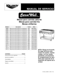
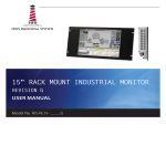
SERVICE MANUAL Hot Food Tables Cold Food Tables Utility Tables Model Description Volts Watts 38002 38003 38004 38005 2-Well Hot Food Table 3-Well Hot Food Table 4-Well Hot Food Table 5-Well Hot Food Table 120V 120V 120V 120V 960 Watts 1440 Watts 1920 Watts 2400 Watts 38102 38103 38104 38105 38106 38107 38108 2-Well Hot Food Table 3-Well Hot Food Table 4-Well Hot Food Table 5-Well Hot Food Table 2-Well Hot Food Table 3-Well Hot Food Table 4-Well Hot Food Table 120V 120V 120V 120V 208V 208V 208V 1400 Watts 2100 Watts 2800 Watts 3500 Watts 1400 Watts 2100 Watts 2800 Watts 38109 38116 38117 38118 38119 5-Well Hot Food Table 2-Well Hot Food Table 3-Well Hot Food Table 4-Well Hot Food Table 5-Well Hot Food Table 208V 240V 240V 240V 240V 3500 Watts 1600 Watts 2400 Watts 3200 Watts 4000 Watts TABLE OF CONTENTS PAGE Operating and Safety Instructions ..................... 2 Troubleshooting ................................................. 5 Exploded View ................................................... 6 Wiring Diagram .................................................. 7 NOTE: WARNING FIRE HAZARD Do not operate this equipment without posts, shelf and legs or casters properly installed. The heating compartment must be separated from the supporting surface of the unit. Warranty ............................................................ 8 Item No. 21609-1 en Rev. 11/12 ServeWell OPERATING AND SAFETY INSTRUCTIONS SERVICE MANUAL 5. Attach the bottom shelf using 8 screws. Remember to face top of shelf toward bottom of base. 6. Assemble each of the four stationary peg legs to the four triangular peg leg mounting plates using locknuts. Nuts are permanently attached inside the plates. 7. Lift unit and place on legs. 8. Place cutting board on top of work surface ASSEMBLY INSTRUCTIONS Note: Place cardboard or drop cloth on floor to protect work surface of unit during assembly. HOT FOOD TABLES 1. Remove all components from shipping container. 2. Place base assembly on floor with well openings down and bottom pan facing up. 3. Assemble drain shut-off faucets to tailpiece below each well. These should be hand tightened until snug. Use Teflon tape and no tools when assembling. Use of tools may cause cracking of the drain assembly resulting in water leaks. . COLD FOOD TABLES Follow steps 1, 2, 4, 5, 6 and 7. UTILITY TABLES Follow steps 1, 2, 4, 5, 6 and 7. ASSEMBLY PARTS LIST Each Vollrath ServeWell unit is packed with the following assembly parts: 4. Attach four legs to base using 16 screws (4 screws per leg). The nuts for these screws are permanently attached inside the base. Description Legs Stationary Peg Legs Screws Shut-off Faucet Note: Item No. 21609 -1 en Rev. 11/12 Page 2 Part Number 28702-2516 23433-1058 26570-1058 23424 Quantity 4 4 32 1 per well Each ServeWell unit will also have the appropriate bottom shelf included. Poly cutting boards will be packed with the hot food servers. Hot well servers will have only one drain faucet (#23424) for each well. ServeWell SERVICE MANUAL WARNING ELECTRICAL SHOCK HAZARD Keep water level at or below the required level. If level is too high, water may overflow when the food container is inserted. The overflow could enter the electrical compartment and cause a short circuit or electric shock. Thank you for purchasing this Vollrath ServeWell food warmer. Before operating this unit, read and familiarize yourself with the following operating and safety instructions. SAVE THESE INSTRUCTIONS FOR FUTURE REFERENCE. WARNING Electric shock, fire or burn injuries can occur if this equipment is not used properly. To reduce risk of injury: Plug only into grounded electrical outlets matching the nameplate rated voltage. Unit should only be used in flat, level position. Unplug hot units and let cool before cleaning or moving. Do not spray controls or outside of unit with liquids or cleaning agents. Handle hot water carefully. Do not operate unattended. 3. Plug power cord into electrical outlet with nameplate rated voltage. 4. Preheat the water in wells by covering wells with empty food containers or covers, and then setting the heat control to the maximum heat setting. Preheat times: Model All models IMPORTANT: Do not operate this unit without water in wells. Preheat Time 60 minutes 5. Place containers of hot food into the preheated food warmer wells. To prevent spills, do not overfill the food containers. 6. Set heat control to maintain safe food holding temperature. Monitor food temperatures closely for food safety. (See food safety note.) FOOD SAFETY PRECAUTIONARY NOTE IMPORTANT: Do not operate this equipment without posts, shelf and legs or casters properly installed. The heating compartment must be separated from the supporting surface of the unit. FUNCTION AND PURPOSE This unit is intended to hold containers of hot food at proper serving temperature. This unit is not designed or intended to cook raw food or reheat prepared food. Monitor food temperatures closely for food safety. The United States Public Health Service recommends that hot food be held at a minimum of 140° F (60° C) to help prevent bacteria growth. Maintain water level at approximately 3/8” from bottom of well. Periodically (approx. 2 hours) remove container of food and check the water level. Add hot water if needed. OPERATION 1. Place the food warmer unit on a flat, stable surface. 2. Fill each well with the following amount of water: Model All models WARNING BURN HAZARD Hot water and steam in the well can burn skin. Use protective gloves, mitts or potholders when removing food containers or covers. Hot food can also cause burns. Handle hot food carefully Amount of Water 4 Quarts The water level mark inside the wells is at approximately 4 Quarts. Do not overfill wells. Do not operate wells without water. Page 3 Item No. 21609-1 en Rev. 11/12 OPERATING AND SAFETY INSTRRUCTIONS HOT FOOD TABLES ServeWell OPERATING AND SAFETY INSTRUCTIONS SERVICE MANUAL NON-REFRIGERATED COLD FOOD TABLES CLEANING To maintain appearance and increase the service life, the food warmer should be cleaned at least daily. FUNCTION AND PURPOSE This non-refrigerated cold food table is intended to be used with ice and hold containers of cold food. It is not designed to lower the temperature of raw or prepared food product. 1. Before cleaning or moving, unplug the unit and let it cool completely. 2. Carefully drain water from wells. 3. Wipe the entire interior of each water pan and well with clean, damp cloth. 4. To avoid damaging the finish, do not use abrasive materials, scratching cleaners or scouring pads to clean water deposits from the wells. 5. Note: The ability to maintain holding temperatures of 40°F or below is influenced by factors that include ambient air temperature, amount of ice, and length of time the food product is held. OPERATION 1. If soap or chemical cleaners are used, be sure they are completely rinsed away with clear water, immediately after cleansing. Chemical residue could corrode the surface of the unit. Partially fill the well with crushed, shaved or cube ice. Position food containers in the well and complete filling the well with ice. Food product should not extend above the level of the ice. If it does, the top layer of the food product will warm rapidly and exceed maximum holding temperature. WARNING WARNING ELECTRICAL SHOCK HAZARD Do not spray water or cleaning product. Liquid could enter the electrical compartment and cause a short circuit or electric shock. HEALTH HAZARD Ice used to hold product is designated as used in a food contact zone. It is subject to food spills and contamination and MUST NOT be used for human consumption. REPAIR There are no user serviceable parts within this appliance. To avoid serious injury or damage, never attempt to repair the food warmer or replace a damaged power cord yourself. 2. Monitor the food temperature frequently for food safety. The United States Public Heath Service recommends that potentially hazardous food be held at 41° F (5° C) or below to help prevent bacteria growth. If safe temperature levels are exceeded, replace the food product with properly chilled food. 3. The recommended maximum depth food pan or container is four inches. This will allow ice to be placed below the pan to aid temperature maintenance. 4. Add ice as needed. Drain excess water. Contact a competent professional repair service. WARNING ELECTRICAL SHOCK HAZARD Do not use this equipment if any well has been removed. Contact with any metal part could cause an electrical shock resulting in severe injury or death. Item No. 21609 -1 en Rev. 11/12 CLEANING Page 4 1. Remove all food product containers from well. Remove any food product that has been spilled on the ice. Discard spilled food product. 2. Place a bucket under the drain and allow the water to flow into the container. Warm water may be poured over the ice to shorten melting time. 3. Wipe interior of well and all surface areas to remove remaining water and food spills. 4. If soap or chemical cleaners are used to clean the metal surfaces, be sure they are completely rinsed away with a clean damp cloth or sponge. Chemical residue may corrode the surface of the cold food table. SERVICE MANUAL UTILITY TABLES FUNCTION AND PURPOSE This utility table is intended to hold non-perishable food products or supplies. It is NOT to be used for the holding or serving of food items that require temperature maintenance for safe consumption. CLEANING 1. Wipe all surfaces with a clean, damp cloth. 2. If soap or chemical cleaners are used to clean the metal surfaces, be sure they are completely rinsed away with a clean damp cloth or sponge. Chemical residue may corrode the surface of the utility table. TROUBLESHOOTING GUIDE Symptom One well does not get as hot as all the others. Elements burn out after a short time. Probable Cause Thermostats could be out of calibration. To test, when the unit is cold, turn the thermostat from the off position slowly to full on. You should hear a “click” at about the second or third position. If the click is heard much later, the thermostats are out of calibration and must be replaced. Knocking the thermostats can cause them to be thrown out of calibration. Check voltage. 208V units are not designed to operate on 240V. Check the power supply. Operators often plug 120V 5-30 and 5-50 plugs into 208V or 240V receptacles. Drains leak. Elements must always be covered with water. If the unit is used without water, the elements will burn out prematurely. Check for obstructions preventing the valve to close properly. Unit heats when thermostat dial is in off position. Plastic drain adapter is cracked where brass reducer or valve is screwed into drain adapter. The drain parts should be hand tightened only. Teflon tape should not be used when installing drain valves. Over-tightening the drain parts will crack the plastic. Thermostat is wired wrong. Wires should be on terminals 1 and 2. Unit does not get hot enough. Thermostat is damaged and must be replaced. Too much water. 480 Watt units should only have 2 Quarts of water and must be preheated with a cover for 1 hour. Check to see the unit has the proper voltage. A unit requiring 120V supply will not perform properly if the voltage supplied is low. Page 5 Item No. 21609-1 en Rev. 11/12 OPERATING AND SAFETY INSTRUCTIONS/TROUBLESHOOTING ServeWell ServeWell EXPLODED VIEW SERVICE MANUAL EXPLODED VIEW Element Part Numbers For Model # Voltage Use Part # 38002, 38003, 120 Volt 44200-1 38004, 38005 38102, 38103, 120 Volt 44204-1 38104, 38105 38106, 38107, 208 Volt 44227-1 38108, 38109 Only 38116, 38117, 208/240 Volt 44277-1 38118, 38119 Poly Cutting Board Part Numbers For Model # Use Part # 38002, 38102, 2-Well Units 23428-1 38106, 38116 38003, 38103, 3-Well Units 23429-1 38107, 38117 38004, 38104, 4-Well Units 23431-1 38108, 38118 38005, 38105, 5-Well Units 23432-1 38109, 38119 Bottom Shelf Part Number For Model # Use Part # 38002, 38102, 2-Well Units 28747-2 38106, 38116 38003, 38103, 3-Well Units 28704-2 38107, 38117 38004, 38104, 4-Well Units 28729-2 38108, 38118 38005, 38105, 5-Well Units 28715-2 38109, 38119 Item No. Part No. 1 See Shelf Chart 2 28702-1 3 28707-2 4 23433-1 5 29838-1 6 17533-1 6 17532-1 7 17868-1 8 See Element Chart 9 17124-1 10 23423-1 11 23540-1 12 17362-1 13 See Cutting Board Chart 14 21607-3 15 17651-3 16 17014-3 17 17741-3 18 23424-2 Item No. 21609 -1 en Rev. 11/12 Description Shelf, bottom Upright leg Bracket, caster Leg, adjustable Caster - 4˝ swivel (optional) Well, plastic (Mfg. After 7/1/00) Well, plastic (Mfg. Before 7/1/00) O-ring, element Element Thermostat Knob, thermostat Switch, toggle. DPST, 30A Drain Adapter Cutting Board Label, switch Screw, #14 x .750 thread cutting Screw, #10-32 x .500 Lg. Clamp, loop Valve and nipple assembly Page 6 Item No. 19 20 21 22 23 24 25 26 27 28 29 30 31 not shown not shown not shown not shown not shown not shown Part No. 17496-3 17365-3 17236-3 44459-2 17504-3 17020-3 25181-3 17019-3 26530-3 17117-1 28799-2 17668-1 17087-1 44407-2 17076-3 26543-3 2327901-1 17559-1 25438-1 This unit shown is a three well unit. The two, four and five well units use the same parts, except where noted. Description Screw, #6-32 x .250 Lg. O-Ring adapter, drain Nut, acorn #10-24 Bracket, high limit switch Element Switch, 347°F +/- 16°F (175 °C) Screw, #6-32 x .500 Lg. Washer, lock - #6 internal tooth #6-32 keps nut Screw, #1/4-20 x .500 Screw, #10-32 x .25 Lg. Spacer, with optional caster Relay switch (Model 38104 & 38105 Only) Screw, #10-32 x .375 Switch and Bracket Assy (ref. 22 and 23) Screw, Thermostat Strain Relief Low Water Light, Blue, 208-240 Volt Low Water Light, Red, 120 Volt Low Water Switch, 250°F +/- 9°F (125 °C) ServeWell SERVICE MANUAL WIRING DIAGRAM WIRING DIAGRAM SERVEWELL OPERATION All units come standard with a properly rated cord and plug. Power is controlled first by a double pole lighted switch. The switch when closed allows power to the thermostats. The thermostats are a capillary bulb thermostat that will react to temperature changes as transmitted to the bulb through the element casting. When the thermostats close, power is then sent to the high limit switch. The high limit switch is normally closed. It will open if the temperature exceed 175° C ± 9° for safety. Power passing through the high limit switch will then energize the element. The neutral wire (or secondary load wire in 208V or 240V systems) from the switch is connected directly to the element. Page 7 Item No. 21609-1 en Rev. 11/12 WARRANTY INFORMATION Warranty Policy for The Vollrath Co. L.L.C The Vollrath Company L.L.C. warranties all products it manufactures and distributes against defects in materials and workmanship for a period of one year - except as listed below: Refrigeration compressors – 5 year warranty Intrigue & Classic Select cookware – Limited lifetime warranty Replacement parts – 90 (ninety days) on the part only Fry pans and coated cookware – 90 (ninety days) All warranties cover normal use and service only and are void if the product has been damaged by accident, neglect, improper use or other causes not arising out of defects in material or workmanship. The Vollrath Company shall not be liable for loss of use of the product or other incidental or consequential costs, expenses or damage incurred by the purchaser. Warranty work must have prior approval from The Vollrath Company L.L.C. ServeWell Warranty All ServeWell models are to be repaired or replaced in the field, at the discretion of The Vollrath Company L.L.C., in accordance with the warranty policy listed above. Should you have a problem with your unit and it is under warranty, please contact an authorized service center nearest to you or call The Vollrath Service number for the location of a service center near you. Please have the model number, series number and date of purchase information available when calling. The Vollrath Company L.L.C. Service Number 1-800-628-0832 The Vollrath Company, L.L.C. th 1236 North 18 Street Sheboygan, WI 53082-0611 U.S.A. Main Tel: 800.624.2051 Service Tel: 800.628.0832 FAX: 800.752.5620 Vollrath of Canada, Ltd. 6320 Danville Road, Unit 1 Mississauga, Ontario L5T 2L7 Canada Tel: 905.565.1167 FAX: 905.565.1168 Item No. 21609 Rev. 11/09