1
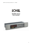
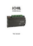
LC-37GP1U
SERVICE MANUAL
No. S47G5LC37GP1U
SUPPLEMENT
LCD COLOR TELEVISION
MODEL
LC-37GP1U
In the interests of user-safety (Required by safety regulations in some countries) the set should be restored to its original condition and only parts identical to those specified should be used.
OUTLINE
In this Service Manual, only parts in the LCD module are shown. For the other points, refer to the LC-37GP1U
(SY6A5LC32GP1U) Service Manual.
Parts marked with "
" are important for maintaining the safety of the set. Be sure to replace these parts with specified ones for maintaining the
safety and performance of the set.
This document has been published to be used for
after sales service only.
The contents are subject to change without notice.
LC-37GP1U
LC-37GP1U
OUTLINE AND ADJUSTMENT
Service Manual
[1] Outline
In this Service Manual, only parts in the LCD module are shown. For the other points, refer to the LC-37GP1U (SY6A5LC32GP1U) Service Manual.
[2] Adjustment
When replacing the LCD control PCB, follow these steps to adjust VCOM.
1) Enter the adjustment process mode.
2) Select the item [VCOM ADJ] on the page 3/27 using the CH (
)/(
) keys on the remote controller.
3) Press the Enter key to check that the adjustment pattern is displayed.
4) Adjust the flicker in the middle of the screen to minimum using the VOL (+)/(-) keys on the remote controller.
5) Press the Enter key to turn off the pattern.
6) To exit the adjustment process mode after the adjustment is done, unplug the AC cord from the outlet to make a forced shutdown. (When the
power was turned off with the remote controller, once unplug the AC cord and plug it again. In this case, wait 10 seconds or so before plugging.)
CAUTION: Use due care in handling the information described here lest your users should know how to enter the adjustment process mode.
If the settings are tampered in this mode, unrecoverable system damage may result.
Description of display
(3) Current selected input
(2) Current page title
(4) Current color system
(6) LCD Panel size/Speaker type
(1) Current page/
(5) Destination
Total pages
1/27
[INFO]
INPUT5
AUTO
USA
MAIN Version
0.90 ( U 2006/11/21 1A)
BOOT Version
SACRB 1.01
Monitor Version
0.9
EQ DATA CHECKSUM
ROM
TEMPAERATURE
7B
LAMP ERROR
0
NORMAL STANDBY CAUSE
0
ERROR STANDBY CAUSE
37_UNDER
(7) Adjustment
process menu
header
(8) Parameters
1)
0
4)
0
2)
0
5)
0
0H 0M
3)
0H 0M
0H 0M
0H 0M
i
0
0H 0M
LC-37GP1U
PartsGuide
PARTS GUIDE
LCD COLOR TELEVISION
MODEL
LC-37GP1U
CONTENTS
[1]
LCD MODULE Assembly
Parts marked with " " are important for maintaining the safety of the set. Be sure to replace these
parts with specified ones for maintaining the safety and performance of the set.
This document has been published to be used
for after sales service only.
The contents are subject to change without notice.
LC-37GP1U
[1] LCD MODULE Assembly
1
8
14
12
14
10
15
9
2
11
3
4
4
13
5
6
6
7
2
LC-37GP1U
NO.
PARTS CODE
PRICE NEW PART
RANK MARK DELIVERY
DESCRIPTION
[1] LCD MODULE Assembly
1
2
3
4
5
6
7
8
9
10
11
12
13
14
15
R1LK370D3LZ2B
CANGK3681TP01
KLMP-A127WJZZ
LHLDZ3382TPZZ
PSLDK2717TPZZ
PSLDK2718TPZZ
POFMD0111TPZZ
QPWBM0327TPZZ
CSLDMA804WJ01
RUNTKA275WJZZ
RUNTKA276WJZZ
CPWBX3520TPZF
XBBSN30P14000
XBPS730P06WS0
PSPAZB030WJKZ
EE
BM
BA
AM
BC
AX
BR
AG
AM
BK
BG
BR
AA
AA
AB
N
N
N
N
N
N
N
N
N
N
N
J
J
J
J
J
J
J
J
J
J
J
J
J
J
J
LCD Module Ass'y
Back Light Angle Ass'y
Lamp Unit, x10
holder, x2
Diffusion Panel
Reflection Sheet, x2
Polarized light reflection sheet
CS-FPC, x2
Shield Case Ass'y
INVERTER Unit A
INVERTER Unit B
LCD CONTROL Unit
Screw, x10
Screw, x12
Spacer, x10
3
LC-37GP1U
2007 BY SHARP CORPORATION
COPYRIGHT © 2007
ALL RIGHTS RESERVED.
No Part of this publication may be reproduced,
stored in a retrieval system, or transmitted in
any from or by any means, electronic, mechanical,
photocopying, recording, or otherwise, without
prior written permission of the publisher.
TQ2189-S YT. DS
SHARP CORPORATION
AV Systems Group
CS Promotion Center
Yaita,Tochigi 329-2193, Japan