1
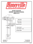
BUCKET ELEVATOR ASSEMBLY AND SERVICE MANUAL MODEL 66-42 Dealer Name: Dealer Order #: Project Name: Honeyville Order #: Elevator Serial #: Discharge Height: Honeyville Metal, Inc. 4200 S 900 W Topeka, IN 46571 Phone (800) 593-8377 Fax (260) 593-2486 www.HoneyvilleMetal.com 12/17/2014 HONEYVILLE METAL, INC. BUCKET ELEVATOR DEALER NAME: MODEL: 66-42 SERIAL NO: DISCHARGE: BELT: BUCKET SIZE: 18" x 8" HEAD BEARINGS: BOOT BEARINGS: BOOT TAKE-UP INFORMATION: When tightening the belt at boot adjustment, always be sure that the belt tracks and is centered in the elevator housing. DRIVE INFORMATION: Model Reducer: Motor Sheave: Driven Sheave: Belts: Motor: HMI Supplied Dealer/Customer Supplied WARNINGS AND SAFETY REMINDERS FOR SCREW, DRAG, AND BUCKET ELEVATOR CONVEYORS CEMA Document: SC 2004-01 APPROVED FOR DISTRIBUTION BY THE SCREW CONVEYOR SECTION OF THE CONVEYOR EQUIPMENT MANUFACTURERS ASSOCIATION (“CEMA”) Honeyville Metal, Inc. (“HMI”) does not install conveyors. It is the responsibility of the contractor, installer, owner and user to install, maintain and operate the conveyor, components and, conveyor assemblies in such a manner as to comply with the Williams-Steiger Occupational Safety and Health Act and with all state and local laws and ordinances and the American National Standards Institute (ANSI) B20.1 Safety Code. In order to avoid an unsafe or hazardous condition, the assemblies or parts must be installed and operated in accordance with the following minimum provisions. 1. 2. 3. 4. 5. Conveyors shall not be operated unless all covers and/or guards for the conveyor and drive unit are in place. If the conveyor is to be opened for inspection cleaning, maintenance or observation, the electric power to the motor driving the conveyor must be LOCKED OUT in such a manner that the conveyor cannot be restarted by anyone; however remote from the area, until conveyor cover or guards and drive guards have been properly replaced. If the conveyor must have an open housing as a condition of its use and application, the entire conveyor is then to be guarded by a railing or fence in accordance with ANSI standard B20.1. (Request current edition and addenda) Feed openings for shovel, front loaders or other manual or mechanical equipment shall be constructed in such a way that the conveyor opening is covered by a grating. If the nature of the material is such that a grating cannot be used, then the exposed section of the conveyor is to be guarded by a railing or fence and there shall be a warning sign posted. Do not attempt any maintenance or repairs of the conveyor until power has been LOCKED OUT. Always operate conveyor in accordance with these instructions and 6. 7. 8. 9. 10. 11. 12. 13. 14. those contained on the caution labels affixed to the equipment. Do not place hands, feet, or any part of your body, in the conveyor. Never walk on conveyor covers, grating or guards. Do not use conveyor for any purpose other than that for which it was intended. Do not poke or prod material into the conveyor with a bar or stick inserted through the openings. Keep area around conveyor drive and control station free of debris and obstacles. Eliminate all sources of stored energy (materials or devices that could cause conveyor components to move without power applied) before opening the conveyor. Do not attempt to clear a jammed conveyor until power has been LOCKED OUT. Do not attempt field modification of conveyor or components. Conveyors are not normally manufactured or designed to handle materials that are hazardous to personnel. These materials which are hazardous include those that are explosive, flammable, toxic or otherwise dangerous to personnel. Conveyors may be designed to handle these materials. Conveyors are not manufactured or designed to comply with local, state or federal codes for unfired pressure vessels. If hazardous materials are to be conveyed or if the conveyor is to be subjected to internal or external pressure, manufacturer should be consulted prior to any modifications. CEMA and HMI insist that disconnecting and locking out the power to the motor driving the unit provides the only real protection against injury. Secondary safety devices are available; however, the decision as to their need and the type required must be made by the owner-assembler as we have no information regarding plant wiring, plant environment, the interlocking of the screw conveyor with other equipment, extent of plant automation, etc. Other devices should not be used as a substitute for locking out the power prior to removing guards or covers. We caution that use of the secondary devices may cause employees to develop a false sense of security and fail to lock out power before removing covers or guards. This could result in a serious injury should the secondary device fail or malfunction. There are many kinds of electrical devices for interlocking of conveyors and conveyor systems such that if one conveyor in a system or process is stopped other equipment feeding it or following it can also be automatically stopped. Electrical controls, machinery guards, railings, walkways, arrangement of installation, training of personnel, etc., are necessary ingredients for a safe working place. It is the responsibility of the contractor, installer, owner and user to supplement the materials and services furnished with these necessary items to make the conveyor installation comply with the law and accepted standards. Conveyor inlet and discharge openings are designed to connect to other equipment or machinery so that the flow of material into and out of the conveyor is completely enclosed. One or more warning labels should be visible on conveyor housings, conveyor covers and elevator housings. If the labels attached to the equipment become illegible, please order replacement warning labels from HMI or CEMA. CEMA has produced an audio-visual presentation entitled “Safe Operation of Screw Conveyors, Drag Conveyors, and Bucket Elevators.” CEMA and HMI encourage the acquisition and use of this source of safety information to supplement your safety program. NOTICE: This document is provided by CEMA as a service to the industry in the interest of promoting safety. It is advisory only and it is not a substitute for a thorough safety program. Users should consult with qualified engineers and other safety professionals. CEMA makes no representations or warranties, either expressed or implied, and the users of this document assume full responsibility for the safe design and operation of equipment. 1 Honeyville Metal, Inc. Model 66-42 Bucket Elevator Assembly & Service Manual CEMA Safety Label Placement Guidelines Note: Labels alone do not substitute for a thorough in-plant safety training program centered on the hazards associated with operating your installed equipment. Contact CEMA (www.cemanet.org) or Honeyville Metal, Inc. for replacement labels. 2 Honeyville Metal, Inc. Model 66-42 Bucket Elevator Assembly & Service Manual ELEVATOR INSTALLATION INSTRUCTIONS Honeyville Metal, Inc. (“HMI”) offers you one of the finest Bucket Elevators in the industry. It has been carefully jig built using only the finest material and quality workmanship. Properly installed, your HMI Elevator should provide you with years of service with a minimal amount of required maintenance. Following are some basic installation tips: I. Inspection upon Delivery HMI Elevators can either be picked up uncrated or be shipped by HMI truck or commercial truck transport. If your elevator was picked up by your own truck, you will have made certain that the load was properly secured to insure that no parts were damaged. If your unit was shipped via, commercial transport, be sure to examine the shipment carefully for damaged parts. Also make certain that all the parts that are listed on the delivery receipt are received. If a damaged part or shortage is noted please contact HMI or the delivering truck driver immediately so that a claim may be filed. II. Check of Components All HMI Elevators are shipped in a maximum of 10' sections. Belting is punched for the proper bucket spacing and rolled. Buckets are normally nested in a box. Head and Boot are usually shipped as individual units. Now that you have located all the major components, there may also be an additional shipment of accessories which you ordered. This may include such items as motors, distributors, ladders, service platforms, elbows, flanges, pipe, valves, pit augers, hoppers, and/or safety cage. III. Advise of any Shortages Although every effort is made to see that your order is shipped complete and in all the correct sizes, mistakes do occur. If you have a shortage or mistake on your order, please accept our apology and notify us at once and we will do everything possible to correct the situation. IV. Base Preparation Larger units, as well as taller ones, will require a concrete base or foundation. If the Elevator base is to be mounted to a basement floor or is installed in a pit where excessive moisture is present, it is recommended that a sump pump or tile is installed to insure a dry, accessible, and safe Elevator boot area. Base plate drawings are available for any size Elevator at your request. These drawings show the size and hole spacing of the Elevator boot flange. Usually four (4) hold down or anchor bolts are adequate for any size unit. Anchor bolts may either be placed in the cement of the boot foundation or holes may be drilled into cured concrete and draw tight anchor bolts placed into position. When a Boot pit is being planned, HMI recommends that adequate space be allowed around the base (18" to 36" in all directions) for servicing and cleanout. 3 Honeyville Metal, Inc. Model 66-42 Bucket Elevator Assembly & Service Manual V. Suggestions For Assembly Assembly bolts and nuts are supplied for connecting the trunking sections. There are a number of ways to erect the Elevator. The shorter units may be assembled, then raised to an upright position and then fastened to some type of support. Inside units are usually stacked, that is, the boot section is set in place and then each section is stacked onto the preceding one with the head section being installed last. Guy wires or cables are then attached to the building structure. If the above method is used, most people set scaffolding around the unit as it is being stacked and the lifting is done by crane. The stacking method (above) is most commonly used when erecting an outside unit. A crane with an adequate reach is set at a proper position to insure a safe working area and then the head section is attached with each trunking section being fastened to the preceding one as the head is raised. If so installed make certain that the head is properly braced where the crane is attached so as to eliminate "Swinging". Yet another method is to lift the head section by the use of a chain hoist or block and tackle and then hanging each section onto the one above. A method which is becoming more and more common with 40' or shorter units is to assemble the elevator complete on the ground, even going so far as to the installation of the belt, buckets, ladder, service platform, and valves. This complete unit is then tilted up into position with a crane. Although this appears to be a simple method, it needs to be done with extreme care to avoid damage to the Elevator. If the crane is not properly attached at several points on the Elevator, trunking can be bent by careless or inexperienced crane handling. HMI cannot accept responsibility for any damage to the Elevator during erection even if the above methods are used. VI. Elevator Bracing Small capacity and shorter units usually require very little bracing. Elevators installed inside a building or along-side some kind of structure can usually be braced to the structure. HMI Elevators are self-supporting; however, they do require guy wires to prevent toppling by the prevailing winds. Guy wires are normally attached to the taller units for support in 3 or 4 directions and are most times attached at or near the service platform. The other ends of the cables are attached to a building or in most cases, to an anchor embedded in the ground. This anchor should be far enough away from the Elevator so that the guy wires extend upwards approximately 45 degrees. Turnbuckles should be used between the anchor post and the end of each guy wire to take up extra slack. It is important that the guy wires be snug but not tight. Too much pressure on the guy wires may damage your Elevator. Taller units may require more than one set of guy wires. Additional sets may be attached at 40' intervals. Standard guy wire material which HMI normally uses is 3/8" or 5/16" Aircraft galvanized steel cable. 4 Honeyville Metal, Inc. Model 66-42 Bucket Elevator Assembly & Service Manual VII. Belt and Bucket Installation As in the actual erection of the Elevator, there are also many techniques for installing the belting and buckets. On all HMI models, the belting is pre-punched for the proper bucket spacing, and then rolled for ease of handling and shipping. The first step prior to installing the belt is to turn the take-up bolts on each side of the boot so that the maximum amount of travel is available. Correct alignment of the head and boot pulley is important since this will prevent edge wear and rubbing of the belts and buckets. If an old belt is being replaced, simply attach one end of the new belt to one end of the old belt and pull the new belt into position by taking the old belt out of the Elevator. One method of belting installation in a new Elevator is to place a clamp on the end of the belt and use a cable or rope to pull the belt into place. Make sure that the entire belt width is gripped securely. Another method is to install all the buckets onto the belt and simply use a crane to lift the belt above the head to drop the belt down on each side of the head pulley. Once the belt is in position, it is necessary to join the two ends of the belt together. Place a belt tightener or take-up unit on each end of the belt and draw it together. A standard lap joint is recommended by HMI. Overlap the ends of the belt approximately 3 to 4 feet and stretch the belt snug. Let the belt hang for at least 24 hours after the buckets have been installed and then stretch the belt again before making the final lap splice. Permitting the belt to remain under tension tends to distribute the stress uniformly throughout the entire belt. If the buckets were not installed on the belt before inserting the belt into the Elevator, this is the next job and should be done prior to making the final lap splice. There is one inspection door on the first trunking section above the boot. This is the access point for installing the buckets. It is recommended that every fifth bucket be put on the belt and rotated until the starting point is reached. Continue this rotation until all the buckets have been installed onto the belt. If every bucket is installed without staggering, the belt might become too heavy to rotate. VIII. Ladder, Safety Cage, and Cross Braces Cross Braces should always be installed on top of the Trunking Flanges (see Page 16). When installing Tie Brackets between two Elevators, the Tie Brackets should be installed under the Trunking Flanges. Offset Ladder Brackets should always be installed with the offset to the left (see Page 16). If one or more Transfer Platform Assemblies are being installed with the ladder and safety cage, be sure to lay out the transfers with the ladder centered between the trunking where it meets the elevator head so that it lines up with the opening in the main platform. The ladder attaches to the elevator head and boot using the Bolt-on Ladder Bracket Sets (L&R) provided (see Page 16). 5 Honeyville Metal, Inc. Model 66-42 Bucket Elevator Assembly & Service Manual IX. Attaching the Accessories Accessories such as hoppers, valves, and motors on small units are no problem, bolts for attachment of all accessories, are included with the Elevator shipment. A common way of installing the accessories, if the Elevator is to be assembled on the ground, is to also install the accessories prior to raising it with the crane. This includes ladder, service platform, valves and even motors. If the stacking method is used in erection, it is advised that the ladder and safety cage be installed with each trunking section (10'). The remaining accessories such as motors, and misc. parts should be lifted into place with a crane. Pipe is usually the last thing to be installed. This is usually raised with the crane or ropes. Angle flanges are supplied with the pipe along with quick clamps so that a minimum amount of welding is required. X. Final Inspection prior to Operation Now that you have successfully erected your HMI Elevator it is advisable that you inspect and check the following items before operation. 1. 2. 3. 4. 5. 6. 7. 8. 9. Check all the bucket bolts to assure that they are tight. Check motor drive V belts to assure that they are snug and in line. Check the motor wiring to assure proper rotation of the belt. Check for any obstruction extending inside of the trunking sections. Check to see that the buckets do not rub the inside of the trunking at any point in the length of travel. Belt alignment can be adjusted by tightening one of the boot take-ups. Check the clearance between the buckets and the discharge adapter cutoff plate in the elevator head and adjust the cutoff plate accordingly. Clearance should be determined at the lap splice of the belt where the buckets will have their greatest projection. Tighten the belt to prevent slipping on the head pulley. Check the oil level in all gearboxes. Once the motor is wired with the proper overload switch, the unit is ready for operation. 6 Honeyville Metal, Inc. Model 66-42 Bucket Elevator Assembly & Service Manual ELEVATOR OPERATION AND MAINTENANCE Following are several pointers that will enable you to get the maximum service from your Elevator: 1. Check bucket bolts after a few days of operation and tighten nuts as required. On new installations, bolt heads will seat into the belt after a few days of operation thus permitting nuts to loosen. 2. Inspect again after three or four weeks of operation to see if nuts have loosened. Continue this inspection at the same interval on units operated continuously. 3. Belt should always be sufficiently tightened to prevent slippage on the Elevator Head pulley. Frequent inspection for belt tension should be made during the first 30 to 90 days of operation. The largest amount of belt stretch will occur during this period. 4. Belt tension is increased by turning down the boot take-up bolts. 5. When checking the buckets for tightness, be sure to examine the joint bolts and tighten, if required. 6. If the Elevator belt tends to run to one side of the pulley during the initial start up, adjust the boot take ups one at a time until the belt runs to the center of the boot pulley. 7. Lubricate all bearings after four to six weeks of continuous operation. Do not over lubricate as this tends to force the grease seals. 8. Lubricate all motors as recommended by the manufacturer. 9. Lubricate all gear reducers according to the manufacturer’s specifications, taking into account the range of ambient temperatures the gear reducer operates in. Honeyville provides gear reducers with the following lubricants: Gear Reducers without internal back stop mechanisms are lubricated with ISO Viscosity Grade 220 Synthetic EP (Extreme Pressure) oil, and Gear Reducers with internal back stop mechanisms are lubricated with ISO Viscosity Grade 220 Synthetic non-EP (non-Extreme Pressure) oil. 10. On farm type installations, which are used seasonally, it is advisable to inspect the elevator prior to heavy use. 11. On installations that require the Elevator boot to be in direct exposure to extreme weather conditions, it is recommended that the take up bolts be liberally treated with lubricating oil or rust preventative. This will make the take-up operate more easily when necessary. 12. It is recommended that water, wet dust, and chaff should not be permitted to collect around the base of the Elevator in the pit. Although HMI constructs the Elevator boot of hot dipped heavy gauge steel, the above conditions will in time cause the boot and lower sections of the structure to rust. 7 Honeyville Metal, Inc. Model 66-42 Bucket Elevator Assembly & Service Manual MAIN PLATFORM ASSEMBLY 8 Honeyville Metal, Inc. Model 66-42 Bucket Elevator Assembly & Service Manual MAIN PLATFORM MOUNTING DETAIL 9 Honeyville Metal, Inc. Model 66-42 Bucket Elevator Assembly & Service Manual DISTRIBUTOR PLATFORM MOUNTING DETAIL 2 1 A DETAIL A 6 4 B 1 3 DETAIL B 1 2 Back (Trunking Side) View 5 5 Front View Item Qty Description 1 6 Trunking Lip Bracket 2 2 Platform Support Mount Angle (33¼”) 3 1 Brace Mount Angle (33”) 4 2 Tab Angle 5 2 Platform Brace 6 2 Distributor Platform Support Angle (R & L) Installation Notes: The holes to mount the Distributor Platform Support Angle to the Platform Support Mount Angle must be drilled in the field The Platform Braces may need to be shortened depending on the distance between the Distributor Platform and the trunking 10 Honeyville Metal, Inc. Model 66-42 Bucket Elevator Assembly & Service Manual DISTRIBUTOR BACK SUPPORT Item Qty Description 1 4 Trunking Lip Bracket 2 2 Platform Support Mount Angle (33¼”) 3 2 Back Support Angle (R & L) 4 1 Back Support Plate Note: Items 1 & 2 are the same as those used for the Distributor Platform Mount 11 Honeyville Metal, Inc. Model 66-42 Bucket Elevator Assembly & Service Manual ELEVATOR BOOT DETAIL Take-up Rod Take-up Guide UHMW Shaft Seal Bearing Mount Take-up Slide 12 Honeyville Metal, Inc. Model 66-42 Bucket Elevator Assembly & Service Manual ELEVATOR JIB BOOM INSTALLATION Upper Bracket Jib Rod This end plate is shipped loose. See #6 below. Lower Bracket Installation Instructions 1) Loosely bolt the Lower Bracket around the elevator head as shown in the drawings above. 2) Bolt the Upper Bracket onto the elevator head angle. a. If holes have not been pre-drilled on the elevator head angle, position the Upper Bracket so that the collars on the Upper & Lower Brackets are in alignment and mark the holes before drilling. The hole sizes should be ¾” 3) Lower the pipe section of the Jib Boom through the Upper Bracket until the sleeve on the pipe rests against the Upper Bracket. 4) Adjust the Lower Bracket for height as needed to secure the end of the Jib Boom pipe and tighten the bolts. 5) Insert the Jib Rod as shown in the drawings to prevent the Jib Boom from turning freely. 6) The end plate on the upper arm is removable, and is shipped loose, to allow for installation of a freewheeling hoist trolley if needed. 13 Jib Boom Upper Bracket Top View Side View Lower Bracket Honeyville Metal, Inc. Model 66-42 Bucket Elevator Assembly & Service Manual LADDER AND SAFETY CAGE PARTS Part Number LDLD1002 LDLD1003 LDSCH001 LDSCH002 LDSCH003 LDSCS009 LDSCS028 LDSCS032 LDSCS048 LDSCS058 Description Service Ladder 5' Section Service Ladder 10' Section Hoop Half for Safety Cage Hoop Extender for Safety Cage on Side-by-Side Ladders Hoop Expander for Flaring Bottom Safety Cage Hoop 9" Safety Cage Strap 14 Ga Galv 28" Safety Cage Strap 14 Ga Galv 32½" Safety Cage Strap 14 Ga Galv 48½" Safety Cage Strap 14 Ga Galv 58½" Safety Cage Strap 14 Ga Galv LDSCH001 Hoop Half for Safety Cage LDSCH002 Hoop Extender for Safety Cage on Sideby-Side Ladders LDLD1002 Service Ladder 5’ Section LDLD1003 Service Ladder 10’ Section LDSCS048 48½” Safety Cage Strap LDSCS058 58½” Safety Cage Strap LDSCH003 Hoop Expander for Flaring Bottom Safety Cage Hoop LDSCS009 9” Safety Cage Strap LDSCS028 28” Safety Cage Strap LDSCS032 32½” Safety Cage Strap 14 Honeyville Metal, Inc. Model 66-42 Bucket Elevator Assembly & Service Manual LADDER AND SAFETY CAGE ASSEMBLY DETAILS Three 9” Safety Cage Straps are required at each ladder section joint. 10’ Ladder Section w/Flared Safety Cage Opening Material List for 10' Ladder Section w/ Flared Safety Cage Opening Item Qty Part Number Description 1 1 LDLD1003 Service Ladder 10' Section 4 4 LDSCH001 Hoop Half for Safety Cage 5 1 LDSCH003 Hoop Expander for Flaring S.C. Hoops 6 3 LDSCS009 9" Safety Cage Strap 14 Ga Galv 7 7 LDSCS028 28" Safety Cage Strap 14 Ga Galv Material List for 10' Ladder Section w/ Standard Safety Cage Item Qty Part Number Description 1 1 LDLD1003 Service Ladder 10' Section 4 6 LDSCH001 Hoop Half for Safety Cage 6 3 LDSCS009 9" Safety Cage Strap 14 Ga Galv 10 14 LDSCS058 58½" Safety Cage Strap 14 Ga Galv ….Hardware for Assembling Safety Cage * 27 HWMB505008 5/16"-18 x 1" Hex Grade 5 Machine Bolt * 27 HWNT0205 5/16"-18 Nut ….Hardware for Bolting Ladder Sections Together * 2 HWMB506012 3/8"-16 x 1½" Hex Grade 5 Machine Bolt * 2 HWNT0206 3/8"-16 Nut * Item not shown 15 20’ Ladder Section w/10’ of Safety Cage + Flared Safety Cage Opening Honeyville Metal, Inc. Model 66-42 Bucket Elevator Assembly & Service Manual LADDER AND SAFETY CAGE ASSEMBLY DETAILS Cross Braces and Offset Ladder Brackets LDOB1001 Offset Ladder Bracket EVCB6642 Cross Brace Installation Tips Cross Braces should be installed on top of the Trunking Flanges. Offset Ladder Brackets should be installed with the offset to the left, as shown above. When installing Tie Brackets between two Elevators, the Tie Brackets should be installed under the Trunking Flanges. Attaching the Ladder to the Elevator Head and Elevator Boot is done using the Bolt-on Bracket Sets (L&R), as shown below. Elevator Head Elevator Boot LDBB1001 Bolt-on Bracket Set for Ladders (L&R) 16 Honeyville Metal, Inc. Model 66-42 Bucket Elevator Assembly & Service Manual LADDER TRANSFER PLATFORM ASSEMBLY Item 1 2 3 4 5 6 7 Part Number LDOB1001 * LDLD1003 LDTP1001 LDSCH001 LDSCH002 LDSCS058 LDSCS009 Quantity based on Ladder Height 40' - 60' 70' - 90' 100' - 120' 130' - 150' 5 5 10 10 1 2 3 4 1 2 3 4 3 6 9 12 4 8 12 16 - Description Offset Ladder Bracket Service Ladder 10' Section Reversible Transfer Platform Hoop Half for Safety Cage Hoop Extender for Safety Cage 58½" Safety Cage Strap 9" Safety Cage Strap Note: Quantities shown above are in addition to standard ladder and safety cage parts already included with your order and is based on 30' between platforms. * Honeyville includes three Offset Ladder Brackets with each Ladder Trasfer Platform Assembly to ensure you have sufficient brackets for your installation. 17 Honeyville Metal, Inc. Model 66-42 Bucket Elevator Assembly & Service Manual LADDER TRANSFER PLATFORM ASSEMBLY 18 Honeyville Metal, Inc. Model 66-42 Bucket Elevator Assembly & Service Manual LADDER TRANSFER PLATFORM ASSEMBLY Transfer Platform Details Transfer Inward to Primary Ladder See Page 20 LDOB1001 Offset Ladder Bracket LDLD1003 Service Ladder 10’ Section See Page 21 for Cross Section View of Typical Offset Ladder with Cage Transfer Platform Details Transfer Outward to Offset Ladder See Page 20 19 Honeyville Metal, Inc. Model 66-42 Bucket Elevator Assembly & Service Manual LADDER TRANSFER PLATFORM ASSEMBLY Transfer Inward to Primary Ladder LDTP1001 Transfer Platform LDSCH002 Hoop Extender for Safety Cage on Side by Side Ladders LDSCH001 Hoop Half for Safety Cage Transfer Outward to Offset Ladder LDSC1058 58½" Safety Cage Strap LDTP1001 Transfer Platform LDSC1009 9” Safety Cage Strap 20 Honeyville Metal, Inc. Model 66-42 Bucket Elevator Assembly & Service Manual LADDER TRANSFER PLATFORM ASSEMBLY Typical Cross Section Top View 21 Honeyville Metal, Inc. Model 66-42 Bucket Elevator Assembly & Service Manual HONEYVILLE DISTRIBUTOR Pipe Control Installation Guide Group 2&3 Pipe Controls (DSPCX-6642) include the following items DSPCA002 Distributor Pipe Controller Group 2&3 Indexer Assembly DSPCDP02 Decal Plate for Group 2&3 Pipe Control See Detail A DSPCCA02 Pipe Control Pipe Coupler for Group 2&3 DSPCM6642 Pipe Control Mounting Kit DSLMBR-6642 Trunking Mount Brackets (Pair) DSIAXXXXX Indexer Assembly Other Items Required for Installation: 1½" Galvanized Pipe 3/32" or 1/8" Cable Cable Clamps Nuts, Bolts, Etc. Indexer Assembly – Detail A Note: Cable must be installed from the Pipe Controller, up through the pipe, and attached to the Indexer Assembly. Note: All Pipe Coupling joints must be tack welded in the field. Attach cable here Optional Pipe Guide EVPG6642 Trunking Mount Brackets Note: Slide Pipe Controller onto Galvanized Pipe and weld. Pipe Control Mounting Kit Pipe Controller Decal Plate 22 Pipe Coupler Honeyville Metal, Inc. Model 66-42 Bucket Elevator Assembly & Service Manual HONEYVILLE DISTRIBUTOR Cable Control Installation Guide Indexer Assembly See Detail A on Page 22 Detail B Attach cable to cable clamp Cable Wheel See Detail B Cable Swivel Assembly Note: Install the pulley assembly at a height that allows the cable to run downward at approximately 45° from the cable swivel assembly. Optional Cable Guide EVCG6642 Other Items Required for Installation: 3/32” or 1/8” Cable Cable Clamps Nuts, Bolts, Etc. Turnbuckle Kits (Three included with each cable control) DSCCTK01 Cable Controller Assembly Optional Triple Swivel Pulley Assembly DSCCPAS3-6642 4:1 Control: Allow at least 60” for cable travel between the Turnbuckles and the Cable Controller. 4:1 Control: Wrap the cable four times each direction for the wheel on the Cable Controller. 23 Honeyville Metal, Inc. Model 66-42 Bucket Elevator Assembly & Service Manual HONEYVILLE DISTRIBUTOR Cable Control Installation Guide 66-42 Pulley Angle Mount Double Swivel Pulley Assembly 4:1 Cable Wheel 66-42 Leg Mount Brackets Cable Swivel Assembly Single Block Pulley Assembly Turnbuckle Kits 4:1 Cable Controller Group 2 & 3 Cable Controls for Model 66-42 Elevators include the following items: Item Qty Part Number Description 1 1 DSCCCA421 4:1 Cable Controller Assembly 2 1 DSCCWH421 4:1 Cable Wheel 3 1 DSCCSA02 Cable Swivel Assembly for Group 2&3 4 1 DSCCPAS2-5436 Double Swivel Pulley Assembly 5 1 DSCCPAB1-5436 Single Block Pulley Assembly 6 2 DSLMBR-6642 66-42 Trunking Mount Brackets (Pairs) 7 2 DSCCPA-6642 66-42 Pulley Angle Mount 8 3 DSCCTK01 Turnbuckle Kits ** 1 DSIAXXXXX Indexer Assembly ** Item is not shown on this page 24 Honeyville Metal, Inc. Model 66-42 Bucket Elevator Assembly & Service Manual perma CLASSIC Automatic Lubricator The perma CLASSIC is Ex-Proof certified, equivalent to USA – NEC 500 and NEC 505 certification. Supplies all lubrication points with grease or oil Fully automatic, maintenance-free Indicates when fully discharged Lubricates up to 12 months, depending on type Can be replaced by hand, without tools Operates in any position Lubricators are non-reusable Replacement Kit: HMPS-RK-1 New Application Kit: HMPS-LK1 Operational Principles By tightening the plastic activating screw, the gas generator falls into the liquid electrolyte. The chemical reaction builds up pressure which causes the piston to move forward. The lubricant is continuously injected into the lubrication point. At the end of the lubrication period the discharge indicator cap becomes clearly visible, indicating the lubricant has been fully discharged due to its transparent casing the movement of the piston can be seen during the lubrication cycle. The delay between activation & lubrication depends on the perma type. The perma CLASSIC & FROST contain 4.8oz (120cc) of lubricant which is also equal to 100 shots of grease. 25 Honeyville Metal, Inc. Model 66-42 Bucket Elevator Assembly & Service Manual perma CLASSIC Automatic Lubricator Installation We recommend activating the unit prior to installing it. Do not expect immediate discharge; operating pressure takes from 1 to 12 days to develop, depending on the PERMA month type. Take the plastic activator and begin to hand tighten into the opening bottom of the PERMA. When the activator becomes hand tight, take a screw driver and insert it through the top ring of the activator (fig.1). PERMA Classic activators are recognized by the Black O-ring seal and Futura activators by their Pink O-ring seal. Continue to tighten until the O-ring breaks off (fig. 2). DO NOT break ring off by hand. This could jeopardize the activation of the PERMA. To insure the activation pellet has fallen from the activator into the bladder that starts the chemical dispensing reaction, simply shake the PERMA to hear the pellet rattle inside. Enter installation & replacement dates on the label. Prior to installation, ALWAYS pre-lubricate the bearing / lubrication point using a hand grease gun filled with the same or compatible grease as the PERMA to ensure it is accepting grease freely. Remove the grease fitting. Remove the black outlet plug from the PERMA canister. Typically most bearing lubrication ports are 1/8” or 1/4”. The PERMA thread is 1/4” MNPT. If the grease inlet is 1/8”, you will need a 1/4” F x 1/8” M adapter (part # B100; fig. 3). If your inlet is 1/4”, you can mount direct. Either way, screw the PERMA into the fitting or bearing hand tight only. Bearing requiring greater amounts of grease can be served by mounting several PERMAS in series using standard PERMA Accessory Parts (fig.4). Grease filled PERMAS may be mounted in any direction (fig. 5), even under water. All Oil filled PERMAS require a check valve at the point of lubrication (part# A810). Remote Installations & Max. Remote Distance w/ NLGI #2 Grease @ 77 F PERMAS may be remote mounted by means of pipe or tubing/hose. This allows for continuous lubrication of hard to reach spots, such as points located inside of machinery guards. Always use 1/4” pipe or 3/8” tubing/hose (150 PSI minimum burst pressure rating). Make sure pipe or tubing is pre-filled with the same or compatible lubricant. 1-month (6 feet), 3-month (4 feet), 6-month (2 feet), 12-month (1 foot) Lower NLGI grades and oil may be remote further distances. Call for assistance. 26