1
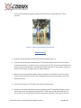
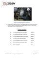
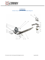
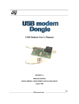
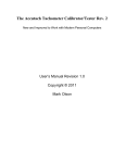
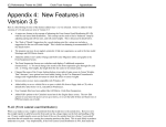
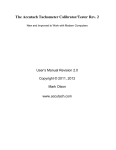
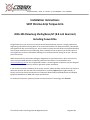
Sonoma Raceway • Boise, ID • 83704 • p: 415.489.0866• f: 415.234.8663 Installation Instructions S197 Xtreme-‐Grip Torque Arm 2005-‐2014 Mustang Shelby/Boss/GT (8.8 inch Rear End) Including Convertible Congratulations on your purchase of a CorteX Xtreme-‐Grip Suspension System. Through professional engineering and extensive testing both on the street and racetracks like Sonoma Raceway, Thunder Hill, and Laguna Seca with record setting cars, we’ve created a system that will deliver unsurpassed handling with minimal modification to your Mustang. After installation of the torque arm you should expect to see a significant increase in forward bit allowing you to accelerate earlier during corner exit. We wish you much success! While the Xtreme-‐Grip suspension package is designed to be minimally invasive, due to the technical nature and specialized equipment required, professional installation is recommended. Go to www.CorteXracing.com for a list of approved installers. CorteX engineers suspension systems designed for ease of installation, we do not install or guarantee proper installation. If you choose to attempt installation of the system yourself, please carefully review these instructions to determine whether you have the tools and experience necessary before beginning disassembly. A factory Ford service manual should also be consulted for disassembly/reassembly details and Original Equipment Manufacturer (OEM) bolt torque specifications. For technical assistance or questions please call CorteX Precision Technology; 415.489.0866 © CorteX Precision Technology 2012 All Rights Reserved Page 1 of 11 Contents Getting Started ............................................................................................................................................ 3 Disassembly ................................................................................................................................................. 4 ASSEMBLY .................................................................................................................................................... 5 APPENDIX E ................................................................................................................................................ 11 © CorteX Precision Technology 2012 All Rights Reserved Page 2 of 11 CAUTION: Installation of the Xtreme-‐Grip suspension package requires working under your Mustang. It is the responsibility of the installer to ensure a safe working environment. The use of an automotive lift is recommended, though installation is possible with use of floor jacks. In either case, always ensure that the vehicle is safely supported with multiple jack stands, and always wear appropriate safety gear and safety glasses. Getting Started Tools and Equipment Needed: • • • • • • • • Floor jack or vehicle lift Jack stands or bottle jacks Metric Socket set Metric end wrench set Electric Drill with large enough chuck to accommodate ½” inch drill bit ½ inch drill bit High-‐torque ½ inch drive pneumatic impact gun Black or Ultra Grey RTV 1. Familiarize yourself with all the items to be installed. 2. Review APPENDIX E that show an exploded view of the parts to be installed. 3. Disconnect the negative cable from the battery. 4. Remove the rear seat to gain access to the large 3rd link upper bolt. Do not remove the bolt at this time. 5. Place vehicle on chassis lift. If a lift is unavailable then raise vehicle with floor jacks and support unibody at lifting points specified in the Ford service manual. 6. With the rear suspension in full droop, position two jack stands under the rear axle with one at each axle tube just inboard of the cast iron center section. Place an additional jack stand under © CorteX Precision Technology 2012 All Rights Reserved Page 3 of 11 the front of the differential pinion to keep the rear end from rotating after the 3rd link is removed. Figure 1: Supporting the Rear End Housing. Disassembly 1. Read the “Getting Started” Instruction Section and complete tasks 1-‐4. 2. These instructions assume the OEM factory 3rd link bracket will be removed from the vehicle. Removing the bracket is an optional step, as only the actual 3rd link needs to be removed for the torque arm to function properly. Removing the bracket eliminates an unnecessary component from the vehicle and is an opportunity for weight reduction. 3. With the vehicle elevated removed the exhaust mid pipes. The tail pipes can remain in place however ensure they are secured so that no damage is done to the rear bumper cover as the exhaust tips move. 4. At this time remove the 3rd link bolt at the top of the axle housing. 5. Remove the two bolts underneath the vehicle attaching the 3rd link bracket. Now get into the vehicle and remove the large bolt attaching the 3rd link bracket located underneath the rear seat. This bolt is very tight and may require a high quality pneumatic impact gun for removal. © CorteX Precision Technology 2012 All Rights Reserved Page 4 of 11 With the bolt removed use a grommet or heavy-‐duty piece of tape to cover the hole keeping moisture and noise out of the interior. 6. The 3rd link bracket in now loose. On 2005-‐2010 Mustang the bracket cannot be removed without loosening the fuel tank. It you would like to remove the bracket loosen the fuel tank strap bolts, lower the tank, and extract the 3rd link bracket. On 2011-‐2014 Mustangs the bracket should come out without loosening the fuel tank. ASSEMBLY 7. The torque arm differential bracket can now be installed. If the vehicle is already equipped with the Xtreme-‐Grip Watts link system you can move directly to mounting the rear differential bracket. If a new differential cover is being installed then drain the differential and removed the OEM cover. 8. With the differential cover removed thoroughly clean the sealing surface. 9. Apply RTV onto the sealing surface of the differential cover and reinstall it on the rear end housing. The 5 lower bolt holes that pass through the rear differential cover bracket will be replaced with new, longer 5/16-‐18 x 1.75”L bolts (5), washer and lock washers following the original installation instructions. The five (5) shoulder bolts are used on the remaining upper holes in the differential cover. Torque each of the 10 bolts 5/16” bolts to 22-‐25 ft-‐lb. 10. Now it is time to move on to the torque arm front mounting. Remove the two bolts attaching the drive shaft center bearing. Set them aside as they will be re-‐used. Also remove the two spacers located between the chassis and center-‐bearing mount. Discard these spacers. 11. The torque arm upper support bracket is “Z” shaped and has two thick tabs that slip between the chassis and the driveshaft bearing mount replacing the discarded spacers. Slip the upper support bracket into position with the tabs facing toward the front of the vehicle and re-‐install the OEM bolts. Leave the bolts loose for now. © CorteX Precision Technology 2012 All Rights Reserved Page 5 of 11 Figure 2: Center Support Bracket in Position. 12. The cross-‐member spans across the floor pan of the vehicle attaching to 4 existing studs protruding from the floor pan. The gain access to the two rearward studs on each side it is necessary to remove the plastic deflectors shown in the figure below. Figure 3: Front Mount Mounting Studs 13. With the plastic deflectors removed the torque arm cross-‐member can now be slide over the studs and bolted down using the two M8 nuts that held the plastic deflectors and two M8 flange nuts provided with the hardware packet. Do not tighten down the nuts at this time. © CorteX Precision Technology 2012 All Rights Reserved Page 6 of 11 14. Apply the supplied white polyurethane grease to the bushing in the front mount. 15. Install the torque arm into the clevis on the differential mounting bracket using the 5/8-‐18 x 3.5L mounting bolt and nut but do not tighten it at this time. 16. Install the front torque arm billet mounting block and with the polyurethane bushing onto the torque arm. The fit is tight so you may need to tap it on with a rubber mallet or us steady pressure and a twisting motion. 17. Rotate the torque arm up and attach the billet front mount to the cross-‐member using the included ½-‐20 x 1.75L grade 8 bolt, ½-‐20 flanged nylock nuts, and ½” grade 8 washer. Take up the slack in the bolts but do not tight at this time. 18. Adjust the angle of the differential so that the two sleeves on the torque arm contact the ears on the differential housing. Ensure the sleeves are somewhere in the middle of each ear so that a ½ inch diameter hole can be drilled without nearing the edge of either ear. Pinion angle is pre-‐ set by the torque arm and does not need to be adjusted. 19. With the torque arm centered with respect to the differential housing, tighten all of the nuts and bolts on the front cross-‐member and center support bracket. © CorteX Precision Technology 2012 All Rights Reserved Page 7 of 11 Figure 4: Front Cross-‐member Installed. 20. Re-‐adjust the pinion angle to make sure the sleeves are still in contact with and centered on each ear of the differential. 21. With everything lined up use the torque arm sleeves as a drilling guide and drill a ½ inch hole in each ear of the differential housing. Clean up all chips and debris after drilling. 22. Install the ½-‐20 x 4.5L bolts from the bottom through the torque arm sleeves. The washers and nuts go on top of each mounting ear. Torque the bolts to 85-‐95 ft-‐lb. 23. Go back and torque the large rear 5/8” cross-‐bolt to 175 ft-‐lb. 24. Make sure all fasteners are properly tightened. © CorteX Precision Technology 2012 All Rights Reserved Page 8 of 11 Figure 5: Exhaust Mid-‐Pipes Reinstalled. 25. Reinstall the exhaust mid-‐pipes. Depending on which year and model of mustang the installation is being done on it may be necessary to re-‐clock the exhaust clamps to gain clearance and avoid exhaust rattle against the torque arm. If sufficient exhaust clearance cannot be achieved it may be necessary to slightly modify the mid-‐pipes to gain additional clearance. Ideally there will be at least ½” of clearance at all locations. 26. Refill the differential with fluid if it was drained with the appropriate fluid as specified by the manufacturer. © CorteX Precision Technology 2012 All Rights Reserved Page 9 of 11 Figure 6: Installed Xtreme-‐Grip Torque Arm 27. Test-‐drive the car and listen for rattles. Some addition road noise will transmit through the torque arm, which is normal however there should not be any banging, or rattling. After approximately 50 miles re-‐torque all fasteners. Hardware Torque Specs: 5X 5/16-‐18” Grade 8 Torque Arm rear bracket 22-‐25 ft-‐lb 5X 5/16-‐18” Shoulder bolts (top 5 on diff cover) 22-‐25 ft-‐lb 2X ½-‐20 x 1.75L Grade 8 Torque Arm Front mount 85-‐95 ft-‐lb 2X ½-‐20 x 4.5L Grade 8 Torque Arm sleeves 85-‐95 ft-‐lb 1X 5/8-‐18 x3.5L Grade 8 Torque arm rear mount 175 ft-‐lb 2X M10 Driveshaft center bearing bolts (OEM) 45 ft-‐lb 4X M8 Floor studs (OEM) 20 ft-‐lb © CorteX Precision Technology 2012 All Rights Reserved Page 10 of 11 APPENDIX E Xtreme-‐Grip Torque Arm Installation Diagram © CorteX Precision Technology 2012 All Rights Reserved Page 11 of 11