1
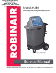
ROBINAIR
○ ○ ○ ○ ○ ○ ○ ○ ○ ○ ○ ○ ○ ○ ○ ○ ○ ○ ○ ○ ○ ○ ○ ○ ○ ○ ○ ○ ○ ○ ○ ○ ○ ○ ○ ○ ○ ○ ○ ○ ○ ○ ○ ○ ○ ○ ○ ○ ○ ○ ○ ○ ○ ○ ○ ○ ○ ○ ○ ○ ○ ○ ○ ○ ○
Service
Manual
Model 34800/34801/AC900
Refrigerant Management Center
CFC 12, HFC 134a Recycling Equipment
Theory of Operation and Safety Precautions ................................... 2
Component Descriptions .................................................................. 3
Flow Diagram Components ............................................................. 6
Flow Diagram ................................................................................... 7
Pictorial View - Front ....................................................................... 8
Manifold Block Flow Diagram ........................................................ 9
Wiring Diagram ............................................................................. 10
Main Board Diagram ..................................................................... 11
Plumbing Schematic ...................................................................... 12
Display Definitions ........................................................................ 13
Control Panel Components ............................................................ 13
Relay Specifications ....................................................................... 14
Relay Troubleshooting ................................................................... 14
Component Specifications .............................................................. 15
Compressor Specifications and Service ......................................... 16
Troubleshooting .............................................................................. 17
Diagnostic Procedures .................................................................... 24
RA19210 Scale Accuracy Check and Recalibration ...................... 25
Checking the Scale Accuracy ......................................................... 25
Recalibrating the Scale ................................................................... 25
Setting the P-1 Pot .......................................................................... 25
Diagnostic Procedures .................................................................... 26
Deep Diagnostic Functions ............................................................ 28
Function Test .................................................................................. 29
ORIGINAL 5/99
34800/34801 Service Manual
Theory of Operation and Safety Precautions
The Series 34800/34801/AC900 recovery, recycling,
evacuation, and recharging units are designed for R-12
and R-134a refrigerants only. These units are UL
approved and meet SAE J-1770 standards.
These units began production in March of 1999, for
AC900 made prior to this date refer to previous AC900
service manual. The model, serial number, and
manufacturing date code can be found on a white tag
located on the back of the unit above the tank.
DEPRESSURIZING THE UNIT
NOTE: Since the series 34800/34801/AC900 has
separate components for each refrigerant type, it is only
necessary to depressurize the side in need of repairs. For
this process you will need a separate hand-held manifold
set.
1. Close both the blue liquid and red vapor valves on the
30 pound recovery tank.
2. Disconnect all hoses from the 30 pound recovery
tank.
3. Disconnect the red high side and blue low side hoses
from a hand-held manifold gauge set.
4. Connect the blue 36" liquid hose to the low side (blue
handle) of the hand-held manifold gauge set. Connect
the red 36" vapor hose to the high side (red handle)
of the manifold gauge set.
5. Connect the yellow hose attached to the center port of
the hand-held manifold gauge set to the inlet of a
separate recovery unit.
6. Open both manifold valves on the hand-held
manifold gauge set.
7. Plug in the separate recovery unit and start its
recovery process.
8. When the hand-held gauge set shows 0 psi, stop the
recovery process. Wait 10 minutes and watch the
hand-held manifold gauges for a pressure rise above
zero. Repeat steps 7 and 8 until positive pressure does
not develop on the hand-held gauge set.
9. Disconnect the blue 36" liquid and red 36" vapor
hoses from the hand-held manifold gauge set.
10. Close the high side manifold valve on the control
panel of the 34800/34801/AC900. Disconnect the red
96" hose from the back of the unit. Connect the
yellow 36" air purge hose to the low side (blue
handle) of a hand-held manifold gauge set. Connect a
hose from the high side port of the machine to the
high side of the hand-held manifold gauge set.
Connect the hose from the center port of the
hand-held manifold set to the inlet of the separate
recovery unit.
11. Open both the high and low side gauge valves on the
control panel of the 34800/34801/AC900 and the
hand-held gauge set.
12. Start the recovery process on the separate recovery
unit.
13. When the pressure on the hand-held gauge set shows
0 psi, stop the recovery process. Wait 10 minutes and
watch the hand-held manifold gauges for a pressure
rise above zero. Repeat Steps 12 and 13 until positive
pressure does not develop on the hand-held gauge set.
WARNING
Always wear safety goggles when working with refrigerants. Contact with
refrigerant can cause eye injury. Disconnect lines and hoses with extreme
caution! Pressurized refrigerant may be present in lines and hoses. Always
point lines and hoses away from you and anyone nearby.
Always unplug the station from the power source before removing any of the
shrouding or beginning any service work.
To order parts, please FAX your order to 1-800-222-7805.
All service related questions should be directed to Robinair at
1-800-822-5561.
2
34800/34801 Service Manual
ORIGINAL 5/99
Component Descriptions
1. 18190A R-134a Low Side Coupler (blue
actuator, smaller I.D.) — Allows access to the low
side of an R-134a system.
• RA19115 Coupler Repair Kit (front O-ring only)
2. 18191A R-134a High Side Coupler (red
actuator, larger I.D) — Allows access to the high
side of an R-134a system.
• RA19115 Coupler Repair Kit (front O-ring only)
3. 62096 R-134a Low Side Hose — Provides flow
from the low side coupler to the low side port on the
station (14mm x ½" Acme).
• 17772 Hose to Coupler O-ring
4. 63096 R-134a High Side Hose — Provides flow
from the high side coupler to the high side port on
the station (14mm x ½" Acme).
• 17772 Hose to Coupler O-ring
5. 68296A R-12 96" Blue Quick Seal Hose — Low
side service hose to the vehicle.
• 18180 Replacement R-12 Quick Seal O-ring
• 18451 45° ¼" Flare Quick Seal Repair Kit
6. 68396A R-12 96" Red Quick Seal Hose — High
side service hose to the vehicle.
• 18180 Replacement R-12 Quick Seal O-ring
• 18451 45° ¼" Flare Quick Seal Repair Kit
7. 68126 36" Red R-134a Tank Hose — Delivers
refrigerant being recovered or recycled to the vapor
side of the R-134a storage tank.
• 17773 Replacement R-134a Quick Seal O-ring
• 40302 R-134a Quick Seal Repair Kit
8. 68127 36" Blue R-134a Tank Hose — Allows
flow from the liquid side of the R-134a tank to the
recycling and charging solenoids.
• 17773 Replacement R-134a Quick Seal O-ring
• 40302 R-134a Quick Seal Repair Kit
9. 68128 36" Yellow R-134a Tank Hose — Supplies
pressure from the top of the recovery tank to the air
purge control.
• 17773 Replacement R-134a Quick Seal O-ring
• 40302 R-134a Quick Seal Repair Kit
10. 68121A 36" Red R-12 Tank Hose — Delivers
refrigerant being recovered or recycled to the vapor
side of the R-12 storage tank.
• 18180 Replacement R-12 Quick Seal O-ring
• 18451 45° ¼" Flare Quick Seal Repair Kit
11. 68122A 36" Blue R-12 Tank Hose — Allows flow
from the liquid side of the R-12 tank to the recycling
and charging solenoids.
• 18180 Replacement R-12 Quick Seal O-ring
• 18451 45° 1/4" Flare Quick Seal Repair Kit
12. 68123A 36" Yellow R-12 Tank Hose — Supplies
pressure from the top of the recovery tank to the air
purge control.
• 18180 Replacement R-12 Quick Seal O-ring
• 18451 450 1/4" Flare Quick Seal Repair Kit
13. RA19393 (RA19402 MacTools) R-134a High
Side Gauge - Reads pressure entering the high side
hose.
14. RA19392 (RA19403 MacTools) R-134a Low
Side Gauge — Reads pressure entering the low
side hose.
15. RA 19393 (RA19400 MacTools) R-12
High Side Gauge — Reads pressure entering the
high side hose.
16. RA19392 (RA19401 MacTools) R-12
Low Side Gauge — Reads pressure entering the
low side hose.
17. 121238 Low and High Side Manifold Valve
R-134a Assembly — Allows refrigerant flow from
the high and low side hoses to the center manifold
port.
18. 121239 Low and High Side Manifold Valve
R-12 Assembly — Allows refrigerant flow from
the high and low side hoses to the center manifold
port.
19. RA19429 Vacuum Pump Protection Switch —
A normally open sensor that closes when pressure
greater than 25 psi is present in the A/C system. If
the pressure is less than 25 psi in the recovery mode,
the display reads “CH-P.” In the vacuum mode, the
display reads “U-HI” if the pressure is 25 psi or
greater in the A/C system. This indicates that a
recovery procedure must be performed before
attempting a vacuum.
20. RA18752 Vacuum Sensor — A normally closed
sensor that sends a signal to the main board when a
13" Hg vacuum has been reached on the inlet line.
21. RA19258 Recovery Solenoid Rebuild Kit — A
normally closed solenoid, designed to prevent the
flow of refrigerant into the system oil separator while
the unit is off or in any mode other than Recovery.
22. RA19258 Recycling Solenoid Rebuild Kit —
A normally closed solenoid that prevents the flow of
refrigerant into the system oil separator when the unit
is not in Recycling Mode.
3
ORIGINAL 5/99
34800/34801 Service Manual
Component Descriptions
23. RA19258 Charging Solenoid Rebuild Kit —
A normally closed solenoid preventing flow into the
A/C system when the unit is turned off or in any
mode other than Charging.
24. RA19258 Vacuum Solenoid Rebuild Kit —
A normally closed solenoid designed to prevent flow
to the vacuum pump during Recovery or Charging.
25. RA15425 (RA15428 220 volt) Vacuum Pump —
A 6 CFM, two stage rotary vane pump designed to
pull moisture and air from an A/C system.
• 120165 Vacuum Tubing
26. System Oil Separator — Performs three
functions. Internal heat evaporates the saturated
vapor, preventing liquid from entering the
compressor. Any oil droplets contained in the
refrigerant drop out in the separator. The system oil
separator's third function is that it acts as a heat
exchanger.
• RA19480 Manifold O-Ring Kit
27. RA19291 Oil Drain Valve — Allows the oil
removed from the system to be drained when
Recovery is complete. The same amount of oil should
be returned during charging.
• RA17419 Oil Drain Bottle
28. 34724 Spin-on Filter-Drier — Removes moisture,
acid, and oil from the refrigerant.
• 40084 Replacement Filter Gasket
29. RA19458 (RA19457 220 volt) Compressor —
Converts low pressure, low temperature incoming gas
into high pressure, high temperature discharge gas.
• 111043 Replacement Start Capacitor
30. Compressor Oil Separator — Traps compressor
oil that has migrated out with refrigerant while
passing through the compressor. The oil is stored in
the separator until the equalization solenoid loses
power and allows the oil to be returned to the
compressor.
• RA19480 Manifold O-Ring Kit
31. RA19258 (RA17578 220 volt) Equalization
Solenoid — A normally closed solenoid that allows
oil trapped in the compressor oil separator to be
forced back into the suction side of the compressor,
equalizing pressure on the high and low side of the
compressor and pressurizing the system oil separator
as power is applied to the solenoid. Opens for 20
seconds after recovery is complete. After the
compressor has run for 10 continuous minutes, the
solenoid opens for three seconds.
4
(continued)
32. RA19427 High Pressure Cutout — A normally
closed sensor that shuts off the unit when the
discharge pressure reaches 435 psi.
NOTE: This switch has three contacts; the outer two
contacts (numbered 1 and 3) are normally closed.
33. RA19326 Recovery Check Valve — Allows flow
in one direction only and prevents refrigerant in the
tank from coming back into the unit during
shutdown.
34. RA19430 Automatic Expansion Valve —
Converts incoming liquid refrigerant into a low
pressure saturated vapor. The calibration of the
expansion valve can be checked at the oil drain with
a pressure gauge. The allowable tolerance of the
valve is 30 to 40 psi during Recycling.
NOTE: Allow the unit to recycle 10 minutes with a
minimum of 10 pounds of refrigerant in the tank before
checking or adjusting the pressure.
35. RA19477 (110V) RA19616 (220V) R-134a Air
Purge Device — After the recycling sequence has
run for 30 seconds, a timer (programmed in the main
board) opens the normally closed solenoid of the
selected refrigerant type, allowing pressure to enter
the lower cavity of the air purge device. When
pressure on the lower cavity exceeds pressure on the
upper cavity by 7 psi or more, a valve inside the
device opens to release the air pressure from the
cavity. When the pressures come within 3 psi of each
other, the device stops purging.
36. RA19476, RA19623 (220V) R-12 Air Purge
Device — After the recycling sequence has run for
30 seconds, a timer (programmed in the main board)
opens the normally closed solenoid of the selected
refrigerant type allowing pressure to enter the lower
cavity of the air purge device. When pressure on the
lower cavity exceeds pressure on the upper cavity by
7 psi or more, a valve inside the device opens to
release the air pressure from the cavity. When the
pressures come within 3 psi of each other, the device
stops purging.
37. 17105 R-12 Recovery Tank — Stores refrigerant
to be recycled at a later time. The tank has two
valves; the vapor valve is an open fitting to the
tankand the liquid valve has a draw tube extending to
within 2 inches of the bottom of the tank.
38. 34705 R-134a Recovery Tank — Stores
refrigerant to be recycled at a later time. The tank has
two valves; the vapor valve is an open fitting to the
tank and the liquid valve has a draw tube extending
to within 2 inches of the bottom of the tank.
34800/34801 Service Manual
ORIGINAL 5/99
Component Descriptions
39. 120034 Oil Injector Assembly — Controls the
flow of oil from the injection bottle to the vehicle.
• 113025 Oil Injector Check Valve
• RA19141 Oil Bottle
• RA19478 Replacement Valve
40. RA19303 (110V), RA19294 (220V), RA19097
(230V) Power Cord — Conducts power to the unit.
41. RA19047 Vacuum Pump Outlet — Female socket
where the vacuum pump power cord connects.
42. RA19343 Main Power Switch — Controls the
power between the power cord and the main board.
(continued)
53. Keypad RA19561 (RA19562 AC900) — Overlay
which contains electronic keypad. All inputs go
directly to circuit board via the ribbon. If a keypad is
bad, all four keys in one row or one column will not
respond.
54. RA19282 Discharge Check Valve — Allows flow
in one direction only and prevents refrigerant and
pressure from the tank from being equalized back
into the low side of the unit when the equalization
solenoid opens to return compressor oil and
repressurize the system oil separator.
43. RA17416 (RA17516 220 volt) Fan — Runs as
soon as the MAIN POWER switch is turned on to
cool the cabinet temperature.
44. 117684 Refrigerant Selector Switch —
Indicates which refrigerant type the machine is set-up
for.
45. RA19564 (110V), RA19618 (220V) (RA19560
MacTools) Main Board — Controls the unit's
functions, automatic or programmed.
46. RA19445 Scale Assembly — Sends a signal to
the main board for accurate weight readings and tank
overfill protection.
47. RA17459 (RA17324 220 volt) System Relay —
Energizes the compressors and vacuum pump,
allowing the sensors to turn off the unit. The relay
has two sets of contacts which close when the coil is
energized.
48. RA19404 Casters
• 113540 Caster Screws (7 required)
• 109525 Caster Nuts (7 required)
49. RA19405 Wheels
• 102755 Wheel Washers (6 required)
• 100723 Cotter Pin (2 required)
50. 112776 Fuse Holder
51. RA17416 (RA17516 220V) Fan — Receives power
when main power is turned on. Cools internal unit
components.
52. RA19545 Manifold Block — Contains recovery,
recycle, recharge and equalization solenoids. Also
located on the block are the Hi-P sensor, vacuum
sensor, vacuum pump, protection switch, expansion
valve, filter, oil and compressor oil separator.
5
ORIGINAL 5/99
34800/34801 Service Manual
Flow Diagram Components
1. 18190A R-134a Low Side Coupler
(blue actuator, smaller I.D.)
2. 18191A R-134a High Side Coupler
(red actuator, larger I.D.)
• RA19115 Coupler Repair Kit (front O-ring only)
16. RA19392 2¾" R-12 Low Side Gauge
(RA19401 Mac Tools)
3. 62096 R-134a Low Side Hose —
• 17772 Hose to Coupler O-ring
18. 121239 R-12 High and Low Side Manifold
Valves
4. 63096 R-134a High Side Hose —
• 17772 Hose to Coupler O-ring
19. RA19429 Vacuum Pump Protection Switch
5. 68296A R-12 96" Blue Quick Seal Hose —
• 18180 Replacement R-12 Quick Seal O-ring
• 18451 450 ¼" Flare Quick Seal Repair Kit
21. RA19258 Recovery Solenoid
6. 68396A R-12 96" Red Quick Seal Hose —
• 18180 Replacement R-12 Quick Seal O-ring
• 18451 450 ¼" Flare Quick Seal Repair Kit
• 11715 Replacement Gauge Lens
17. 121238 R-134a High and Low Side Manifold
Valves
20. RA18752 Vacuum Sensor
22. RA19258 Recycling Solenoid
23. RA19258 Charging Solenoid
24. RA19258 Vacuum Solenoid
25. RA15425 (RA15428 220 volt) Vacuum Pump
7. 68126 36" Red R-134a Tank Hose —
• 17773 Replacement R-134a Quick Seal O-ring
• 40302 R-134a Quick Seal Repair Kit
26. System Oil Separator
8. 68127 36" Blue R-134a Tank Hose —
• 17773 Replacement R-134a Quick Seal O-ring
• 40302 R-134a Quick Seal Repair Kit
29. RA19458 (RA19457 220 volt) Compressor
9. 68128 36" Yellow R-134a Tank Hose —
• 17773 Replacement R-134a Quick Seal O-ring
• 40302 R-134a Quick Seal Repair Kit
27. RA19291 Oil Drain Valve
28. 34724 Spin-on Filter-Drier
30. Compressor Oil Separator
31. RA19258 Equalization Solenoid
32. RA19427 High Pressure Cutout
33. RA19326 Recovery Check Valve
10. 68121A 36" Red R-12 Tank Hose —
• 18180 Replacement R-12 Quick Seal O-ring
• 18451 450 ¼" Flare Quick Seal Repair Kit
34. RA19430 Expansion Valve
11. 68122A 36" Blue R-12 Tank Hose —
• 18180 Replacement R-12 Quick Seal O-ring
• 18451 450 1/4" Flare Quick Seal Repair Kit
37. 17105 R-12 Recovery Tank
12. 68123A 36" Yellow R-12 Tank Hose —
• 18180 Replacement R-12 Quick Seal O-ring
• 18451 450 1/4" Flare Quick Seal Repair Kit
13. RA19393 (RA19402 MacTools) R-134a High
Side Gauge —
• 11715 Replacement Gauge Lens
14. RA19392 (RA19403 MacTools) R-134a Low
Side Gauge —
• 11715 Replacement Gauge Lens
15. RA19393 2¾" R-12 High Side Gauge
(RA19400 MacTools)
• 11715 Replacement Gauge Lens
6
35. RA19477 (RA19616 220v) R-134a Air Purge
36. RA19476 (RA19623 220v) R-12 Air Purge
38. 34705 R-134a Recovery Tank
39. 120034 Oil Injector Assembly
43. RA17416 (RA17516 220v) Fan
47. RA19445 Scale Assembly
11
37
12
10
47
55
36
23
31
32
30
34
26
22
39
R-12
20
5
27
29
28
21
18
19
33
14 13
43
24
6
3
25
24
1
33
19
28
27
17
29
21
13 14
4
20
2
23
30
32
31
26
34
22
39
35
R-134a
55
9
38
7
8
47
34800/34801 Service Manual
ORIGINAL 5/99
Flow Diagram
7
ORIGINAL 5/99
34800/34801 Service Manual
Pictorial View of Front
39
54
35
31
36
53
48
30
31
26
53
28
30
29
28
52
26
29
*
48
*
INST0542
26. System Oil Seperator
28. 34724 Spin-on Filter-Drier
48. RA17459 (RA19562 220v) System Relay
29. RA19458 (RA19457 220v) Compressor
52. RA17416 (RA17516 220 volt) Fan
30. Compressor Oil Seperator
53. RA19545 Manifold Block
31. RA19258 Equalization/Oil Return Solenoid
54. RA19561 (RA19562 Mac Tools) Keypad
35. RA19477 (RA19616 220v) R-134a Air Purge Device
*111043 Replacement Start Capcitor
36. RA19476 (RA19623) 220 Volt) R-12 Air Purge
Device
39. 120034 Oil Injector Assembly
8
34800/34801 Service Manual
ORIGINAL 5/99
Manifold Block Flow Diagram
34
33
19
21
24
23
22
39
39
25
20
29
36
OR
35
31
28
26
30
32
55
9
ORIGINAL 5/99
34800/34801 Service Manual
Wiring Diagram 34800/34801 & AC900
INST0563
10
34800/34801 Service Manual
ORIGINAL 5/99
Main Circuit Board Diagram
INST 0518
11
ORIGINAL 5/99
34800/34801 Service Manual
Plumbing Schematic
A
A
B
C
B
E
D
F
D
I
G
H
N
L
J
M
O
K
P
R
Q
INST0655
12
Letter
Qty.
Description
A.
B.
C.
D.
E.
F.
G.
H.
I.
J.
K.
L.
M.
N.
O.
P.
Q.
R.
2
2
1
2
1
1
1
1
2
1
1
1
1
1
1
1
1
1
Hose, 1/4" O.D.
Hose Assembly
Air Purge Inlet Tube
Tubing, 3/8" O.D. (22.0')
Pneumatic Connector, 3/8 Tee
Air Purge Inlet Tube
Liquid Inlet Tube
Liquid Inlet Tube
Block Inlet Tube Refrigerant
Compressor Discharge Line
Compressor Return Oil Line
Compressor Suction Line
Compressor Discharge Line
Compressor Return Oil Line
Compressor Suction Line
Tubing, 3/8" O.D. (10')
Accumulator Oil Drain
Accumulator Oil Drain
120225
120887
121188
120165
121311
121195
121189
121196
121191
121185
121186
121187
121192
121193
121194
120165
121190
121197
34800/34801 Service Manual
ORIGINAL 5/99
Display Definitions
CH-P
CL-L
CON
CPL
Less than 24 psi at the inlet of the machine.
The low side clearing routine is in progress.
The vacuum pump runs continuously.
The specified cycle function (recovery, evacuation, charging or adding refrigerant) is complete.
FIL
The filter-drier change is in progress.
FULL The refrigerant recovery tank is full.
HI-P Internal pressure in unit is above 435 psi.
OIL
Time to change the vacuum pump oil. To reset,
press MODE and ENTER at the same time while
“OIL” is displayed.
SCAL The scale is damaged, disconnected, out of
calibration or overloaded. It cannot exceed 45
pounds total weight.
U-HI There is positive pressure on the vacuum pump.
Press MODE, then RECOVER to remove the
pressure. Continue the evacuation procedure.
Control Panel Components
16
15
42
44
14
13
53
INST0546
13. RA19393 (Mac Tools RA19402) R-134a High Side
Gauge
14. RA19392 (Mac Tools RA19403) R-134a Low Side
Gauge
42. RA19343 Main Power Switch
44. 117684 Refrigerant Selector Switch
53. RA19561 (RA19562 AC900) Keypad
15. RA19393 (Mac Tools RA19400) R-12 High Side
Gauge
16. RA19392 (Mac Tools RA19401) R-12 Low Side
Gauge
13
ORIGINAL 5/99
Relay Specifications
RA17459 (RA17324 220 volt) System
Relays
The system relay is used to energize the compressor or the
vacuum pump and allow the sensors to shut the unit off.
The relay has two sets of contacts which close when the
coil is energized.
Coil contacts 0 and 1, when energized, should have 110
volts across the terminals. While voltage is applied, the
coils forms a magnetic field pulling the 2 and 4 and the 6
and 8 contacts together.
The 2 and 4 and the 6 and 8 contacts have power supplied
to one terminal of the pair. When the coil is energized and
supplies power to the mating component.
Troubleshooting
Manual Override Ear Not Pulled In
1. Check the proper voltage to the 0 and 1 contacts. If
there is voltage, replace the relay. If there is not
voltage, replace the main board.
Manual Override Ear Pulled In
1. check for proper voltage from the power supply
contact to ground. If there is no voltage, check the
voltage supply source.
2. check for proper voltage from the mating supply
contact to ground. If there is no voltage, replace the
relay.
NOTE: Use of improper extension cord size can damage
contact points.
14
34800/34801 Service Manual
34800/34801 Service Manual
ORIGINAL 5/99
Component Specifications
RA18752 Vacuum Sensor
20
The vacuum sensor is a normally closed sensor. If a 13"
(+2") Hg rating is reached at the intake, the switch opens
and breaks the coil contacts, shutting off the unit. The contacts are closed when a vacuum above 13" Hg is present in
the lower cavity. When a 13" Hg vacuum is achieved in the
lower cavity, the spring contact has room to force away from
the mating contact.
TROUBLESHOOTING
With pressure in the accumulator (open the oil drain valve
to be sure pressure is present), the switch should have continuity. If it does not, replace the switch.
If the unit is shutting off before reaching a 13" Hg vacuum,
check the inlet for obstructions before replacing the switch.
RA19427 High Pressure Cutout
32
The high pressure cutout is a normally closed sensor designed to shut the unit off if the discharge pressure reaches
435 psi.
Pressure is detected through the orifice in the base of the
sensor. In the normal setting (less than 435 psi on orifice),
the 1 and 3 contacts are closed. When 435 psi is introduced
to the orifice, the pressure forces up on the drive pin which
forces the center contact to disengage the 1 and 3 contact
and engage the 1 and 2 contacts. When this takes place, the
unit shuts off and the display reads “HI-P.”
19
RA19429 Vacuum Pump Protection
Switch
The vacuum pump protection switch is a normally open sensor. If a 25 psi (+2") psi rating is reached at the intake, the
switch closes, sending a signal to the main board.
The contacts are closed when anything greater then 25 psi
is present in the lower cavity. When 25 psi is achieved in
the lower cavity, the spring contact is forced into the mating
contact.
15
ORIGINAL 5/99
34800/34801 Service Manual
Compressor Specifications and Service
Blue/White R-134a
Blue/White R-134a
Blue Black R-12
Blue Black R-12
Brown/White R-134a
Brown/Black R-12
Brown/White R-134a
Brown/Black R-12
COMPRESSOR SPECIFICATIONS
Type:
1/3 hp hermetic (piston type)
compressor
Oil Capacity:
10 ounces (296 milliliters)
Oil Type:
150 viscosity POE refrigeration oil
Voltage:
100-110V iunits use a RA 19458
220V units use a RA19457
Amperage:
4-6 running amperage (100-110V)
20-25 locked rotor amperage
3-4.5 running amperage (220V)
16-19 locked rotor amperage
CHECKING THE OIL
1. Depressurize the unit.
2. Remove the compressor from the unit and place on a
flat surface.
3. Tilt the compressor 30 degrees (see figure above). At
this angle, there should be oil in the suction fitting.
ADDING OIL
1. Install a funnel in the suction fitting and pour two
ounces of oil into the funnel.
2. Start the compressor momentarily. Plug the intake
fitting but leave the discharge fitting open. The
compressor will pull oil from the funnel. Stop the
compressor.
3. Check the oil level. If it is still low, add 2 ounces at a
time until a proper level is achieved.
16
Suction and Discharge Pressure Test
1. Disconnect all fittings from the unit.
2. Cap the intake fitting.
3. Install a low side gauge on the suction fitting.
NOTE: The fittings used on these compressors require an
0-ring fitting to seal and a 120063 hose (1/4" flare o-ring
X 1/2" Acme Q.S.) with an R-134a manifold set.
4. Verify that the discharge fitting is unobstructed.
5. Start the compressor and monitor the suction
readings. The compressor should pull a 25" Hg (-.85
bar) vacuum. If the compressor has weak suction,
check the oil level and add if necessary. If the oil
level is okay or oil was added with no improvement,
replace the compressor.
6. Disconnect the low side gauge on the discharge
fitting.
7. Install a high pressure gauge on the discharge fitting.
NOTE: The fittings used on these compressors require an
0-ring fitting to seal and a 120063 hose (1/4" flare o-ring
X 1/2" Acme Q.S.) with an R-134a manifold set.
8. Verify that the intake fitting is unobstructed.
9. Start the compressor and monitor the pressure for
about 4 minutes. If pressure doesn’t reach at least 350
psi (24 bar), replace the compressor.
34800/34801 Service Manual
ORIGINAL 5/99
Troubleshooting
UNIT WILL NOT COME OUT OF CL-L,
COMPRESSOR RUNS
(WILL NOT RECOVER)
1. If the unit is being run through an extension cord,
eliminate its use.
2. Disconnect the high and low side hose from the
vehicle with the gauge valves open. If the pressure on
the gauges drops while the display shows CL-L, the
recovery solenoid may need to be replaced or rebuilt.
3. Check the oil drain valve. Verify that it is closed and
not bleeding through.
4. Install the low side hose on the oil drain with the low
side valve closed. Check the gauge. If it has positive
pressure, go to Step 5. If psi is below a 20" Hg
vacuum, test the vacuum sensor for continuity. If
there is continuity, replace the sensor. If there is no
continuity, check the vacuum sensor wires for
continuity. If the wires have continuity, replace the
main board.
5. Close the tank’s liquid valve. If pressure starts
dropping on the gauge and the unit starts a recovery
sequence, clean and rebuild the recycling solenoid.
6. Inspect the filter for flow obstructions and check for
leaks around the gasket area.
7. If the equalization solenoid is receiving power,
replace the circuit board.
8. Check the compressor discharge and suction
pressure.
UNIT WILL NOT COME OUT OF CL-L,
COMPRESSOR IS OFF
(WILL NOT RECOVER)
1. If the unit is being run through an extension cord,
eliminate its use.
2. Remove the shroud and look for loose wires.
3. Check for voltage to the coil of the compressor replay
(energized). If there is no voltage, check the wires
fromt he main board to the compressor relay for
continuity. If they have continuity, replace the main
board.
4. If the compressor relay is energized, (receiving 110/
220 volts) check for voltage from the #4 contact to
ground with a volt meter (it should be 110/220 volts).
If there is no voltage, replace the compressor relay.5.
Check for voltage to the compressor. If there is no
voltage, check the wires between the compressor and
the compressor relay for continuity. Repair or replace
as necessary.
6. If voltage is present at the compressor, jumper the
thermal overload. If the compressor runs, check the
compressor amp draw. If it is drawing higher than 6
amps or not running, replace the compressor. If the
compressor is cool and drawing low amperage,
replace the thermal overload.
17
ORIGINAL 5/99
34800/34801 Service Manual
Troubleshooting
UNIT WILL NOT START
1. Check to be sure both tank valves are open.
OR COMPLETE RECOVERY
2. Check the tank pressure. It should not exceed 300
psi. If the pressure is high, bleed the pressure down to
200 psi by recycling and allowing the automatic air
purge to operate.
3. Check the red vapor tank hose for proper installation.
Be sure there is no obstruction at the tank fitting.
4. Check the 2 amp fuse on the back of the main board
for continuity and replace if necessary. If the
replacement fuse blows, check the compressor relay
for shorted contacts. Replace as necessary.
5. Check the wires between the high pressure cutout and
the main board for continuity. Repair or replace as
necessary.
6. Replace the high pressure cutout and retest the unit.
Display Reads FULL
1. Check the tank weight and replace the tank if it is
full.
2. Recalibrate the scale if necessary.
3. Adjustment of the P-1 pots (see main board diagram
for location) may be necessary. See “Setting the P1pot" in the function test for detailed instructions.
4. Verify that the scale is connected properly.
Display Reads CPL
1. Verify that there is positive pressure on the unit’s
manifold gauges. If there is no positive pressure,
connect to a vapor supply source and attempt
recovery again.
2. Look for loose or broken wires in the unit.
3. Verify that the suction line strainer is not plugged.
See tubing schematic for location.
4. Install the low side hose (coupler) on the oil drain
with the low side valve closed. Open the oil drain
valve. Look for a psi reading. If the pressure is below
13" Hg, test the vacuum sensor for continuity. If the
vacuum sensor has continuity, replace it. If it does
not, check the vacuum sensor wires for continuity. If
the wires have continuity, replace the main board.
5. If there is no positive pressure, verify that the inlet
check valve is operating properly. Also, verify that
the recovery solenoid is opening and allowing flow.
Repair and replace as necessary.
18
34800/34801 Service Manual
ORIGINAL 5/99
Troubleshooting
UNIT WILL NOT START OR COMPLETE
RECOVERY (continued)
Display Reads "CH-P"
1. If there is less than 25 psi at the inlet, attempt
recovering from a positive pressure source.
2. Verify that the wires that control the vacuum pump
protection switch have continuity.
3. If there is more than 25 psi at the inlet, verify no
obstructions in the manifold valves. Then replace the
vacuum pump protection switch.
4. If the sensor is operating properly, press CONT to
override.
5. If the main board will not let you override, verify that
the keypad is sending the signal. If it is, replace the
main board. If it is not sending a signal, replace the
keypad.
Display Reads "CH-F"
1. The filter change time has elapsed. To reset the timer,
refer to the operating manual for the filter change
procedure.
2. If, after attempting to reset the timer, the “CH-F”
warning does not disappear, replace the main board.
Display Reads "15.00 Vacuum Program Minutes"
1. If the display does not respond to keypad commands,
verify that the keypad is plugged in. If the keypad is
plugged in but not responding, replace the keypad. If
the keypad is functional, a tone sounds when a key is
pressed.
Display Reads "Scale"
1. Check the scale calibration and P1-pot adjustments.
Recalibrate and adjust as necessary. Refer to function
check for detailed instructions.
2. Check the scale cable to be sure it is connected to the
main board.
3. Disconnect the scale cable from the main board and
jumper the white and black leads. If the display still
reads “Scale”, replace the main board. If the display
clears the message “Scale”, replace the scale.
19
ORIGINAL 5/99
34800/34801 Service Manual
Troubleshooting
UNIT WILL NOT EVACUATE,
1. Verify that the manifold gauge valves are open.
PUMP IS RUNNING
2. Verify that the high and low side hoses (couplers) are
tight at all fittings.
3. Check the oil injector tubing for leaks and loose
connections.
4. Be sure the vacuum hose is snug at both ends and not
obstructed. Check the hose gaskets for leaks.
5. Check for suction at the intake of the pump. If there
is none, replace the pump.
6. Remove the shroud and look for loose wires to the
vacuum solenoid.
7. Check for voltage to the vacuum solenoid. If voltage
is present, rebuild the solenoid or inspect for debris.
8. If no voltage is present, check the lead wires for
continuity. If continuity is present, replace the main
board.
9. Check the low side gauge for proper operation and
calibration.
UNIT WILL NOT EVACUATE,
PUMP IS OFF
"U HI" on Display
1. Be sure pressure is present at the vacuum protection
switch. Recover before evacuation. Unplug the
switch.
2. If U HI goes out, check for pressure at the sensor.
If there is none, replace the sensor.
3. If U HI remains on, replace the main board.
Timer Counting Down
1. Verify that the vacuum pump is plugged in.
2. Check the voltage at the pump receptacle.
3. If proper voltage is present, be sure that the pump is
not overfilled with oil. If it is, drain the pump. Start
and properly refill the pump. If proper voltage is
present, replace the pump.
4. If proper voltage is not present, remove the shroud
and look for loose wires.
5. Check the voltage to the vacuum pump relay coil.
If there is no voltage, check the wires between the
vacuum pump relay and the main board for
continuity. If the wires are okay, replace the main
board. If there is voltage at the vacuum pump relay
coil, replace the relay.
6. Check for voltage from the #4 contact to ground.
If there is no voltage, replay the relay.
20
34800/34801 Service Manual
ORIGINAL 5/99
Troubleshooting
UNIT WILL NOT RECYCLE,
RECYCLE PROMPT IS OFF (NO FLOW)
NOTE: When the vacuum key is pressed, the unit
automatically recycles. Recycle stops when the vacuum
timer is down to three minutes. When recycle stops, the
power is dropped to the recycle solenoid. The compressor
continues to run until the Accum Oil separator and the
filter reach a 13" vacuum.
1. Check that all recovery tank hoses are properly
installed.
2. Verify that the recovery tank valves are completely
open.
3. Be sure there is a minimum of 10 pounds of
refrigerant in the tank.
4. Install the low side of a manifold gauge set to the oil
drain.
5. If positive pressure is present at the service port,
remove the cover and look for loose wires to the
vacuum sensor. If there are no loose wires, check for
continuity on the vacuum sensor. If there is none,
replace the vacuum sensor.
6. Inspect the orange wires between the main board and
the vacuum sensor for continuity. If the wires and the
vacuum sensor have continuity, jumper the orange
wires together.
7. Start recycling if the service port is being pulled into
a vacuum. Look for loose wires to the recycling
solenoid and verify that 110 volts is being sent to the
recycling solenoid. If there is no voltage, inspect the
controlling wires for continuity. Replace the main
board if the wires have continuity.
8. Verify that you have flow through the blue tank hose
and the moisture indicator. Replace and clean as
necessary.
9. If the hose or moisture indicator is not plugged,
attempt to recalibrate the expansion valve. If you are
unable to recalibrate the expansion valve, rebuild the
recycling solenoid and replace the expansion valve.
10. If all previous attempts have failed, replace the main
board.
21
ORIGINAL 5/99
34800/34801 Service Manual
Troubleshooting
UNIT WILL NOT PERFORM AN
AIR PURGE
NOTE: The air purge only operates the first 10 minutes
of recycling and then drops power to the air purge
solenoid. A minimum of six pounds of refrigerant must be
in the tank for the air purge to function properly.
1. Verify that the recovery tank has excess air pressure
in it. The only accurate way to do this is to connect a
hand-held manifold gauge set to the recovery tank's
air purge fitting, check the pressure in the tank and
compare it with a temperature/pressure chart.
2. If excess air pressure is confirmed, verify that all
recovery tank hoses are properly connected to the
tank.
3. Slowly open the yellow hose where it attaches to the
back of the unit. If the tank is allowing access and the
yellow hose is unobstructed, pressure is released.
Repair and replace as necessary.
4. If the yellow hose has flow, remove the front cover
and verify that the exhaust port of the air purge
device is not obstructed.
5. After recycling for at least three minutes, verify that
110/220 volts is being sent to the air purge solenoid.
If it is not getting 110/220 volts, inspect the control
wires for continuity. Repair or replace as necessary. If
the air purge solenoid is getting 110/220 volts, go to
Step seven.
6. If the wires have continuity, replace the main board.
7. If the solenoid is receiving 110/220 volts, remove the
air purge device. Rebuild or replace as necessary.
UNIT WILL NOT CHARGE,
1. Verify that the tank's liquid valve is open.
NO PRESSURE ON GAUGES
2. Verify that the manifold valves are completely open
and unobstructed.
3. Inspect the liquid hose for proper installation on the
tank and check for crushed hose gaskets.
4. Verify that the main board has accepted the program.
5. Remove the shroud and look for loose wires.
6. If the main board does not accept the program,
replace it. Be sure the keypad is sending a program
signal before replacing. If the keypad is sending a
signal, an audible tone sounds when keys are pressed.
7. Check the voltage at the charging solenoid. If there is
no voltage, check the lead wires for continuity. If the
wires have continuity, replace the main board. If
there is proper voltage to the solenoid, replace the
solenoid.
22
34800/34801 Service Manual
ORIGINAL 5/99
Troubleshooting
UNIT WILL NOT CHARGE,
PRESSURE ON GAUGES
1. Verify that the unit is gaining access to the A/C
system.
2. Be sure there is a minimum of six pounds of
refrigerant in the tank.
3. Be sure the scale is able to move freely.
4. Verify that the unit is charging through both the high
and low side hoses.
5. Check for proper voltage to the charging solenoid
(not an erratic voltage drop). If the voltage is okay, go
to step six. If there is a problem with the voltage,
replace the main board.
6. Close the high side valve, start the engine and pull in
the remaining charge on the low side of the system.
When the remaining charge has been pulled from the
tank, the charging solenoid closes, preventing a
possible overcharge.
23
ORIGINAL 5/99
34800/34801 Service Manual
Diagnostic Procedures
AC900
Press MODE and ENTER simultaneously to enter diagnostics. Use the UP and DOWN keys to select the mode and
press ENTER to start the mode.
F00—LB/KG mode select
ENTER toggles between modes. MODE locks the chosen mode.
F01—Diagnostic Vacuum
Vacuum only. Mode switch may be changed between R-12 and R-134a in
this mode and a vacuum is pulled on the chosen side.
F02—UL Circuit Adjustment
Setting the P1-pots.
F03—Filter Weight
Displays weight recovered through the filter on whichever side R-12 or R-134a is
selected. Mode switch may be changed between R-12 and R-134a without exiting,
allowing both filter weights to be checked. Press RECOVER and RECYCLE ONLY
to reset.
F04—Audit Trail
Displays date and number of scale calibrations. Press RECOVER and RECYCLE
ONLY keys simultaneously to set the number of calibrations to 001.
F05—Segment Test
Lights all segments of the LCD.
F06—Calibration Test
Checks the scale accuracy.
F07—Refrigerant Weight
Estimated weight of refrigerant in the selected tank is displayed. Because tank
weights vary, this can only be considered an estimate. Either tank can be selected in
this mode by moving the mode switch between R-12 and R-134a.
F08—Step Test
When this mode is entered, the display blanks. Press RECOVER and RECYCLE
ONLY keys simultaneously to continue. The display counts up from 001 to 015 as
corresponding outputs are cycled on and off. this test can be accelerated at any time
by pressing any key. After the step test, the display gives a code for any input that is
not in its normal state, as listed. To continue when this occurs, the input must be
put into its normal state. If all inputs are in their normal state, the unit resumes
normal operation.
Input Codes
"r12 - "CH-P" R-12 Vacuum Protection Switch
"r12 - "CL-L" R-12 Low Pressure Switch
r134" - "CH-P" R-134a Vacuum Protection Switch
r134a - "CL-L" R-134a Low Pressure Switch
"ref" - R-12/R-134a Mode Switch
F09 - Scale Calibration
See RECALIBRATING THE SCALE for detailed instructions.
F10 - Default Codes
When this mode is entered, the display blanks. Press RECOVER and RECYCLE
ONLY keys simultaneously to continue. The display shows a three-digit code that
controls the default oil timer, filter weight, and vacuum time. The default value for
this code is 356. The first digit represents the default vacuum time and is multiplied
by 5 minutes to get the default. The second digit represents the vacuum pump oil
timer and is multiplied by 2 hrs. to get the default. The third digit represents the
default filter weight and is multiplied by 50 lbs. to get the default. This code can be
changed by using the UP and DOWN arrow keys. The ENTER key locks in the new
code and resets the unit with the new settings.
F11 - F99
Not used.
24
34800/34801 Service Manual
ORIGINAL 5/99
Scale Accuracy Check
and Recalibration for AC900
CHECKING THE SCALE ACCURACY
1. Turn on the MAIN POWER switch.
2. Press the MODE key until the program prompt is
highlighted on the screen.
3. When the screen has the program prompt
highlighted, press the MODE and ENTER keys
simultaneously to enter the DIAGNOSTIC mode.
4. Remove all weight from both scale platforms.
5. Using the UP and DOWN keys, toggle the display to
read F06.
6. Press the ENTER key to turn the scale into a direct
reading weight scale.
NOTE: Whatever weight is on the scale when ENTER is
pressed will not be shown on the display. Be pressing
ENTER, the unit automatically zeros the weight on the
scale of the selected regfrigerant type. If you remove the
weight, the display shows the change in total weight, but
does not show a negative sign. The refrigerant selector
switch may be changed during the procedure to check
both scales.
If the scales does not react to testing, verify that the scales
are plugged into the main board.
RECALIBRATING THE SCALES
1. Remove all weight from the scale platform.
2. Turn on the main power switch.
NOTE: If the unit is just being turned on, the screen
defaults to display the selected refrigerant type. Press
MODE until the program message is displayed.
3. Press the MODE and ENTER keys simultaneously to
enter the DIAGNOSTIC mode. Use the UP and
DOWN keys to toggle the display to F09.
9. The display flashes A1, then displays 0.00.
10. Place a certified weight, between 10 and 40 lbs., in
the center of the scale platform. Using the UP and
DOWN keys, toggle to that weight on the display.
Press ENTER.
11. The display flashes “134A” then displays “ZEro”
(zero).
12. The display flashes “A1” then read “0.00”.
13. Place a certified weight, between 10 and 40 pounds,
in the center of the scale platform. Using the UP and
DOWN keys, toggle to that weight on the display,
then press ENTER. The display then shows the
selected refrigerant type.
14. Check the scale accuracy.
SETTING THE P-1 POT
1. Remove all weight from the scale platforms.
2. Turn on the MAIN POWER switch.
NOTE: If the unit is just being turned on, the screen will
default to display the selected refrigerant type. Press
MODE until the program message is displayed.
3. Press the MODE and ENTER keys simultaneously to
enter Diagnostic Mode. Use the UP and DOWN keys
to toggle the display to “F02”.
4. Press the ENTER key. The screen will display “000”.
NOTE: The zero on the left of the display is for R-12,
and the zero on the right of the display is for R-134A.
Since the AC900 uses two 30 lb. tanks, the full limit
should be set at 43 lbs.
6. Using the UP and DOWN keys, enter the current
month and year. For example, if the unit is being
calibrated in August of 1999, enter 0-8-9-9. Press
ENTER.
5. Place a known weight of 43 lbs. on the R-12 scale.
The zero on the left of the display should change to a
“1”. The display should be reading “100”. At this
point, adjust the R-12 P-1 pot so the full limit is set at
43 lbs. Turning the P-1 pot clockwise will decrease
the amount of weight you can put on the scale before
the zero changes to a “1”which indicates the full
limit has been reached. Turning the P-1 pot
counterclockwise will increase the amount of weight
allowed before the zero changes to a “1” indicating
that the full limit has been reached.
7. The display flashes r12, then displays ZEro (zero).
6. Repeat step 5 on the 134A scale.
4. Press the ENTER key. The display now reads CAL.
5. Press the RECOVER and VAC/RECYCLE keys
simultaneously. The display flashes DATE and then
shows 0.00.
8. Make sure nothing is on or touching the R-12 scale
platform. Press ENTER.
NOTE: The zero on the right of the display indicates the
134A full limit. Once the 134A full limit is reached, the
display reads “001”.
25
ORIGINAL 5/99
34800/34801 Service Manual
Diagnostic Procedures
34800 and 34801
All diagnostic modes mentioned here are accessed by entering the diagnostic functions menu. Press the SHIFT and
ENTER keys simultaneously. The unit's display prompts you for the function to run by displaying FUNC. Unless
otherwise noted, pressing RESET accepts the current settings and returns the unit to normal operation.
STANDARD FUNCTIONS
0 - LBS OR KG MODE SELECTION
ENTER toggles the current mode. The current mode is displayed
by either the lbs. or the kg. segments.
1 - Diagnostic Vacuum
The refrigerant mode switch selects which "side" of the unit to
pull a diagnostic vacuum on. To exit from this routine, look for
the U-HI message or press HOLD. From either of these two
states, a RESET returns the unit to normal operation.
2 - Add Refrigerant
The current refrigerant mode is assumed. The process begins
immediately upon the start of this function. Therefore, the liquid
hose must already be disconnected from the correct tank and
attached to the reserve tank that is being added from. The display
shows ADD briefly and then the amount of refrigerant transferred
by weight. The function continues the transfer until one of the
following occurs: HOLD is pressed, the reserve tank is empty and
pulled to a partial vacuum, or the maximum fill weight of the
function has been reached. Under the last two conditions, the
display flashes between CPL and the amount of refrigerant
transferred by weight. In the HOLD condition, pressing HOLD
again resumes the operation.
3 - Accumulated Filter Weight
Displays total accumulated filter weight. Press the CHARGE and
ENTER keys simultaneously to reset the counter to zero.
4 - Audit Trail
Displays date of last calibration and how many calibrations have
been performed on the scales (to a maximum of 225.) Pressing
CHARGE and ENTER simultaneously also returns this counter
to zero.
5 - Segment Test
This test lights all segments of the LCD for quick indication that
the display rountines and circuitry are functioning properly.
26
34800/34801 Service Manual
ORIGINAL 5/99
Diagnostic Procedures
34800 and 34801 (continued)
6 - Scale Calibration Check
Display reflects any absolute weight change on the selected
scale. Upon entry to this mode, the display briefly shows which
refrigerant mode you are in, then displays 0.00. If the refrigerant
mode switch changes states, the display repeats this indication
for the selected "side." To zero the reading, press 6 at any time.
This process is useful for adding weight to check positive
response and then removing weight to check negative response.
Upon exit, the weights will NOT be updated to reflect what was
done to the scales.
7 - Refrigerant Weight
Display indicates estimated refrigerant by weight in the selected
tank. This weight is obtained by the program by subtracting the
coded tank weight from the total weight seen by the scale.
Because of this variation in tank weights, this figure should only
be used as an estimate. The refrigerant mode switch allows you
to select which tank to use.
8 - Unused Function
Returns unit to normal operation.
9 - Gateway to Deep Diagnostics
Display shows four dashed lines which prompt entry of coded
special functions. These functions directly affect large portions
of the unit's operation.
27
ORIGINAL 5/99
34800/34801 Service Manual
Deep Diagnostic Functions
NOTE: Pressing the RESET key has no effect on any of these functions.
SCALE CALIBRATION
The display briefly shows DATE, then 0.00. Enter the date in the following format: MM.YY. press ENTER to
accept the entry. The display now briefly shows r12, followed by ZEro. Make sure there is no weight on the R12
scale and press ENTER. The display now shows A1 and then 0.00. Place a known weight on the R12 scale and
enter the value of the weight. Press ENTER to accept.
The display now briefly shows 134a, then shows ZEro. Make sure there is no weight on the R-134a scale and press
ENTER The display now briefly shows A1, then 0.00. Place a known weight on the R-134a scale and enter the
value of the weight. Press ENTER to accept. The unit updates its programming and returns to normal operation.
3 - UL CIRCUIT ADJUSTMENT (P1-pot)
The P1-pots on the 34800 are located on the front of the circuit board. The pot on the left is for the R-12 scale, and
the pot on the right is for the R-134a scale. Turning the pot counter-clockwise increases the full limit. Turning the
pot clockwise decreases the full limit. Enter the deep diagnostic mode by pressing 9 when the FUNC message
displays.
Four dashed lines appear on the display. Press 3 on the keypad. The display shows 000. The zero on the left is for
R-12. The zero on the right is for R-134a. Since this machine uses 30lb. tanks, the full limit should be set at 43 lbs.
When 43 lbs. is placed on the R-12 scale, the zero on the left should change to a number one (1). When the zero
changes to a one, you have reached the full limit on the R-12 scale.
Remove a small amount of weight from the scale and watch for the number one to change back to zero. Repeat this
process on the R-134a scale. The only difference is that the zero on the right of the display indicates whenther or
not you have reached the full limit on the R-134a scale. This change is indicated by the change from zero to the
one, then back to zero again.
DIAGNOSTIC STEP TEST
Push Shift-Reset and Enter at the same time
Then push 9
Then push 5
Push 6 and 9 at the same time
01
R-134a
Recycle Solenoid
09
R-12
Recover Solenoid
02
R-134a
Recover Solenoid
10
R-12
Vacuum Solenoid
03
R-134a
Vacuum Solenoid
11
R-12
Charge Solenoid
04
R-134a
Charge Solenoid
12
R-12
Air Purge Solenoid
05
R-134a
Air Purge Solenoid
13
R-12
Compressor Relay
06
R-134a
Compressor Relay
14
07
R-134a
Equalization Solenoid
15
08
R-12
Recycle Solenoid
28
Vacuum Pump Relay
R-12
Equalization Solenoid
34800/34801 Service Manual
ORIGINAL 5/99
Function Test
RECOVERY CHECK
1. Turn on the MAIN POWER switch.
2. Install the loose end of the low side hose (coupler) to
the oil drain.
3. Close the low side manifold valve.
4. Open the high side manifold valve.
5. Verify that all tank hoses are properly attached to the
recovery tank.
6. Completely open both tank valves.
7. Press RECOVER. The compressor starts and the low
side gauge pulls into a 13" Hg vacuum.
NOTE: The unit’s low side gauge pulls to a 13" Hg
vacuum and starts the recovery process. Recovery is
engaged when the scale reading is displayed. The low side
gauge pulls to a 13" Hg vacuum again and the unit shuts
off.
8. When recovery is complete, the display shows a scale
weight, then display the “CPL” message.
9. The low side manifold gauge builds positive pressure
and a pressure transfer should be heard. This is the
result of the equalization solenoid opening and
returning oil to the compressor. If no pressure rise
occurs, the equalization solenoid and its tubing must
be inspected for obstructions.
10. Disconnect the low side hose (coupler) from the
service port and open the low side manifold valve.
11. Press RECOVER. The unit recovers to 13" Hg of
vacuum and shuts off.
EVACUATION & RECYCLING CHECK
NOTE: The recovery tank must have at least 6 pounds of
refrigerant in it to perform this test.
1. Close the high side manifold valve.
2. Install the loose end of the low side hose (coupler)
from a separate hand-held manifold gauge set to the
service port. Verify that the valves are closed on the
hand-held manifold gauge set.
3. Program a 20 minute vacuum into the main board
and start the automatic vacuum process. The vacuum
pump starts.
4. Verify that the low side manifold valve on the unit’s
control panel is open.
5. The low side gauge on the unit starts registering a
vacuum.
6. Within 10 seconds of the vacuum pump starting, the
RECYCLE prompt appears on the display and a click
is heard. The compressor is starting and the recycling
solenoid is being energized.
7. After 60 seconds of recycling, the air purge solenoid
receives 110/220 volts to open it. If air is being
purged, the solenoid is getting 110/220 volts. In some
cases, no air is present and the voltage needs to be
checked to verify the solenoid operation.
8. After 5 minutes, the low side gauge on the unit’s
control panel is in a 29" to 30" Hg vacuum.
9. The low side gauge on the hand-held manifold gauge
set rises to around a 30 to 40 psi reading (expansion
valve pressure). If the expansion valve setting is not
in range, adjust accordingly.
10. The low side manifold gauge on the unit’s control
panel should hold a vacuum. If it does not, inspect
the hoses for leaks.
12. Close the tank’s red vapor valve.
13. Disconnect the tank’s red vapor hose from the tank.
14. Using a separate manifold gauge set, verify that the
manifold gauge valves are closed.
15. Connect the tank’s red vapor hose to the high side of
the separate manifold gauge set.
16. Connect the hose from the center port of the handheld manifold gauge set to the tank’s vapor fitting.
29
ORIGINAL 5/99
17. Open the tank’s red vapor valve. Do not open the red
high side valve on the hand-held manifold gauge set.
34800/34801 Service Manual
CHARGING AND SCALE CHECK
1. Turn on the MAIN POWER switch.
18. Use the RECYCLE ONLY function. The unit begins
recycling and the high side manifold gauge starts
increasing pressure.
19. The unit shuts off when the high side manifold gauge
shows a pressure of 435 psi (+20 psi). The display
shows the “HI-P” message.
20. There is an initial drop in pressure to around 275/300
psi. After the initial drop in pressure, the pressure
should hold for 3 minutes. If the pressure drops
instantly or bleeds off steadily, the recovery check
valve needs to be replaced.
23. After checking for pressure loss, slowly open the high
side manifold valve to equalize the unit and tank
pressure.
24. Once the pressure is equalized, close the tank’s red
vapor valve.
25. Close the high side manifold valve and disconnect (at
the tank end) the hose between the tank’s red vapor
valve and the manifold gauge set.
26. Disconnect the tank’s red vapor hose from the
manifold gauge set.
27. Reconnect the tank’s red vapor hose to the tank’s red
vapor valve.
28. Open both manifold gauge valves on the unit’s
control panel and press RECOVER. Allow the unit to
recover until it automatically shuts off.
2. Check the scale accuracy and recalibrate if necessary.
See Scale Section for detailed instructions.
3. Install the high and low side hoses to the vapor and
liquid valves of a separate reusable cylinder.
4. Program a two pound charge into the main board.
5. Open both manifold gauge valves and start the
automatic charging process. The charging process
stops when the programmed amount of weight has
been lost from the scale. The display shows the
“CPL” message.
6. Recover the refrigerant charged into the tank.
7. Repeat full function test for the other refrigerant type
as necessary.
NOTE: To ensure a complete charge, recycle for at least
five minutes before attempting to charge. During this
process the refrigerant is heated in the recovery tank.
Labor Rates
Robinair authorizes a 2 hour charge to troubleshoot
and complete a full function test on units that are
covered under factory warranty. This includes leak
testing. The authorized time for parts replacement is
15 minutes per part. If repairs are estimated to
exceed 3 hours, prior authorization from Robinair is
required.
Filters are considered to be a consumable item and, as
such, they are not covered under the factory warranty.
This includes parts and labor.
30