1
Reliability is a
beautiful thingTM
STACKABLE CRESCENT CUBER
KM-1800SAH/3
KM-1800SWH/3
KM-1800SRH/3
SERVICE MANUAL
NUMBER:
™
73131
ISSUED: November 11, 2005
REVISED: December xx, 200x
IMPORTANT
Only qualified service technicians should attempt to service or maintain this
icemaker. No such service or maintenance should be undertaken until the
technician has thoroughly read this Service Manual.
HOSHIZAKI provides this manual primarily to assist qualified service technicians in the
service and maintenance of the icemaker.
Should the reader have any questions or concerns which have not been satisfactorily
addressed, please call or write to the HOSHIZAKI Technical Support Department for
assistance.
HOSHIZAKI AMERICA, INC.
618 Highway 74 South
Peachtree City, GA 30269
Attn: HOSHIZAKI Technical Support Department
Phone: 1-800-233-1940 Technical Service
(770) 487-2331
Fax:
1-800-843-1056
(770) 487-3360
Web Site: www.hoshizaki.com
NOTE: To expedite assistance, all correspondence/communication MUST include the
following information:
• Model Number
• Serial Number
• Complete and detailed explanation of the problem
2
Please review this manual. It should be read carefully before the icemaker is serviced or
maintenance operations are performed. Only qualified service technicians should service
and maintain the icemaker. This manual should be made available to the technician prior to
service or maintenance.
CONTENTS
I. Specifications...................................................................................................................... 5
A. Icemaker ....................................................................................................................... 5
1. KM-1800SAH (air-cooled) ....................................................................................... 5
2. KM-1800SAH3 (air-cooled, 3 phase)....................................................................... 6
3. KM-1800SWH (water-cooled) .................................................................................. 7
4. KM-1800SWH3 (water-cooled, 3 phase) ................................................................. 8
5. KM-1800SRH (remote air-cooled) ........................................................................... 9
6. KM-1800SRH3 (remote air-cooled, 3 phase) ........................................................ 10
B. Condensing Unit.......................................................................................................... 11
1. URC-20F ............................................................................................................... 11
II. General Information ......................................................................................................... 13
A. Construction ................................................................................................................ 13
1. KM-1800SAH/3...................................................................................................... 13
2. KM-1800SWH/3..................................................................................................... 14
3. KM-1800SRH/3 ..................................................................................................... 15
B. Controller Board .......................................................................................................... 16
1. Solid-State Control ................................................................................................ 16
2. Controller Board .................................................................................................... 16
3. Sequence .............................................................................................................. 20
4. Controls and Adjustments ..................................................................................... 23
5. Checking the Controller Board .............................................................................. 26
III. Technical Information ...................................................................................................... 27
A. Water Circuit and Refrigerant Circuit........................................................................... 27
1. KM-1800SAH/3...................................................................................................... 27
2. KM-1800SWH/3..................................................................................................... 28
3. KM-1800SRH/3 ..................................................................................................... 29
B. Wiring Diagrams .......................................................................................................... 30
.................................................................................................. 30
1. KM-1800SAH
2. KM-1800SAH3....................................................................................................... 31
3. KM-1800SWH, KM-1800SRH ............................................................................... 32
4. KM-1800SWH3, KM-1800SRH3 ........................................................................... 33
C. Timing Chart ............................................................................................................... 34
D. Performance Data ....................................................................................................... 36
1. KM-1800SAH......................................................................................................... 36
2. KM-1800SAH3....................................................................................................... 37
3. KM-1800SWH........................................................................................................ 38
4. KM-1800SWH3...................................................................................................... 39
5. KM-1800SRH ........................................................................................................ 40
6. KM-1800SRH3 ...................................................................................................... 41
3
IV. Service Diagnosis ........................................................................................................... 42
A. No Ice Production ....................................................................................................... 42
B. Evaporator is Frozen Up ............................................................................................. 45
C. Low Ice Production ..................................................................................................... 46
D. Abnormal Ice ............................................................................................................... 46
E. Other ........................................................................................................................... 47
V. Removal and Replacement of Components .................................................................... 48
A. Service for Refrigerant Lines ...................................................................................... 48
1. Refrigerant Recovery............................................................................................. 48
2. Evacuation and Recharge [R-404A] ...................................................................... 48
B. Brazing ........................................................................................................................ 49
C. Removal and Replacement of Compressor ................................................................ 49
D. Removal and Replacement of Drier ............................................................................ 50
E. Removal and Replacement of Expansion Valve.......................................................... 51
F. Removal and Replacement of Hot Gas Valve, Line Valve and Gas Valve.................... 52
G. Removal and Replacement of Evaporator .................................................................. 53
H. Removal and Replacement of Thermistor................................................................... 53
I. Removal and Replacement of Fan Motor ..................................................................... 54
J. Removal and Replacement of Water Valve .................................................................. 54
K. Removal and Replacement of Pump Motor ................................................................ 55
L. Removal and Replacement of Spray Tubes................................................................. 55
M. Removal and Replacement of Water Regulating Valve – Water-Cooled Model Only . 56
N. Adjustment Of Water Regulating Valve – Water-Cooled Model Only .......................... 57
O. Removal and Replacement of Condensing Pressure Regulator (C.P.R.) –
Remote Air-Cooled Model Only .................................................................................. 58
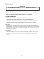
VI. Cleaning and Maintenance............................................................................................. 59
A. Preparing the Icemaker for Long Storage ................................................................... 59
B. Cleaning and Sanitizing Instructions ........................................................................... 60
1. Cleaning Procedure ............................................................................................... 61
2. Sanitizing Procedure - Following Cleaning Procedure .......................................... 62
C. Maintenance ............................................................................................................... 63
4
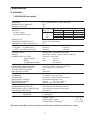
I. Specifications
A. Icemaker
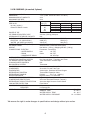
1. KM-1800SAH (air-cooled)
AC SUPPLY VOLTAGE
AMPERAGE
MINIMUM CIRCUIT AMPACITY
MAXIMUM FUSE SIZE
APPROXIMATE ICE PRODUCTION
PER 24 HR.
lbs./day ( kg/day )
Reference without *marks
SHAPE OF ICE
ICE PRODUCTION PER CYCLE
APPROXIMATE STORAGE CAPACITY
ELECTRIC & WATER CONSUMPTION
ELECTRIC W (kWH/100 lbs.)
WATER gal./24HR (gal./100 lbs.)
EXTERIOR DIMENSIONS (WxDxH)
EXTERIOR FINISH
WEIGHT
CONNECTIONS - ELECTRIC
- WATER SUPPLY
- DRAIN
- CONDENSATE DRAIN
CUBE CONTROL SYSTEM
HARVESTING CONTROL SYSTEM
ICE MAKING WATER CONTROL
COOLING WATER CONTROL
BIN CONTROL SYSTEM
COMPRESSOR
CONDENSER
EVAPORATOR
REFRIGERANT CONTROL
REFRIGERANT CHARGE
DESIGN PRESSURE
P.C. BOARD CIRCUIT PROTECTION
COMPRESSOR PROTECTION
REFRIGERANT CIRCUIT PROTECTION
LOW WATER PROTECTION
ACCESSORIES -SUPPLIED
-REQUIRED
OPERATING CONDITIONS
208-230/60/1 (3 wire with neutral for 115V)
18 A ( 5 Min. Freeze AT 104°F / WT 80°F)
30 A
30 A
Ambient
WATER TEMP. (°F)
Temp.(°F)
50
70
90
70
*1756 (797)
1685 (764)
1589 (721)
80
1702 (772)
1592 (722)
1496 (679)
90
1685 (764)
*1514 (687)
1416 (642)
100
1579 (716)
1491 (676)
1326 (601)
Crescent Cube
42.9lbs. (19.4 kg) 2160 pcs.
N/A
90/70°F
70/50°F
2979 (4.9)
2780 (3.8)
348 (23.0)
680 (38.7)
48" x 27 3/8" x 36 7/16" (1219 x 695 x 925 mm)
Stainless Steel, Galvanized Steel (Rear)
Net 344 lbs. ( 156 kg ), Shipping 440 lbs. ( 200 kg )
Permanent - Connection
Inlet
1/2" FPT
Outlet
3/4" FPT
3/8" OD Pipe
Float Switch
Hot Gas and Water, Thermistor and Timer
Timer Controlled. Overflow Pipe
N/A
Thermostat
Hermetic, Model CS18K6E-PFV-237
Air-cooled, Fin and Tube Type
Vertical type, Stainless Steel and Copper
Thermostatic Expansion Valve
R-404A,
4 lb. 7 oz. ( 2000 g )
High 467 PSIG, Low 230 PSIG
High Voltage Cut-out ( Internal )
Auto-reset Overload Protector ( Internal )
Auto-reset High Pressure Control Switch
Float Switch
N/A
Ice Storage Bin
VOLTAGE RANGE
187 - 253 V
AMBIENT TEMP.
45 -100° F
WATER SUPPLY TEMP.
45 - 90° F
WATER SUPPLY PRESSURE
10 - 113 PSIG
We reserve the right to make changes in specifications and design without prior notice.
5
2. KM-1800SAH3 (air-cooled, 3 phase)
AC SUPPLY VOLTAGE
AMPERAGE
MINIMUM CIRCUIT AMPACITY
MAXIMUM FUSE SIZE
APPROXIMATE ICE PRODUCTION
PER 24 HR.
lbs./day ( kg/day )
Reference without *marks
SHAPE OF ICE
ICE PRODUCTION PER CYCLE
APPROXIMATE STORAGE CAPACITY
ELECTRIC & WATER CONSUMPTION
ELECTRIC W (kWH/100 lbs.)
WATER gal./24HR (gal./100 lbs.)
EXTERIOR DIMENSIONS (WxDxH)
EXTERIOR FINISH
WEIGHT
CONNECTIONS - ELECTRIC
- WATER SUPPLY
- DRAIN
- CONDENSATE DRAIN
CUBE CONTROL SYSTEM
HARVESTING CONTROL SYSTEM
ICE MAKING WATER CONTROL
COOLING WATER CONTROL
BIN CONTROL SYSTEM
COMPRESSOR
CONDENSER
EVAPORATOR
REFRIGERANT CONTROL
REFRIGERANT CHARGE
DESIGN PRESSURE
P.C. BOARD CIRCUIT PROTECTION
COMPRESSOR PROTECTION
REFRIGERANT CIRCUIT PROTECTION
LOW WATER PROTECTION
ACCESSORIES -SUPPLIED
-REQUIRED
OPERATING CONDITIONS
208-230/60/3
11 A ( 5 Min. Freeze AT 104°F / WT 80°F)
20 A
20 A
Ambient
WATER TEMP. (°F)
Temp.(°F)
50
70
90
70
*1757 (797)
1683 (764)
1597 (724)
80
1701 (772)
1587 (720)
1507 (684)
90
1683 (764)
*1506 (683)
1422 (645)
100
1579 (716)
1486 (674)
1344 (610)
Crescent Cube
42.9 lbs. (19.4 kg) 2160 pcs.
N/A
90/70°F
70/50°F
2949 (4.7)
2562 (3.5)
328 (21.8)
694 (39.5)
48" x 27 3/8" x 36 7/16" (1219 x 695 x 925 mm)
Stainless Steel, Galvanized Steel (Rear)
Net 344 lbs. ( 156 kg ), Shipping 440 lbs. ( 200 kg )
Permanent - Connection
Inlet
1/2" FPT
Outlet
3/4" FPT
3/8" OD Pipe
Float Switch
Hot Gas and Water, Thermistor and Timer
Timer Controlled. Overflow Pipe
N/A
Thermostat
Hermetic, Model CS18K6E-PFV-237
Air-cooled, Fin and Tube Type
Vertical type, Stainless Steel and Copper
Thermostatic Expansion Valve
R-404A,
4 lb. 7 oz. ( 2000 g )
High 467 PSIG, Low 230 PSIG
High Voltage Cut-out ( Internal )
Auto-reset Overload Protector ( Internal )
Auto-reset High Pressure Control Switch
Float Switch
N/A
Ice Storage Bin
VOLTAGE RANGE
187 - 253 V
AMBIENT TEMP.
45 -100° F
WATER SUPPLY TEMP.
45 - 90° F
WATER SUPPLY PRESSURE
10 - 113 PSIG
We reserve the right to make changes in specifications and design without prior notice.
6
3. KM-1800SWH (water-cooled)
No Data Available
We reserve the right to make changes in specifications and design without prior notice.
7
4. KM-1800SWH3 (water-cooled, 3 phase)
No Data Available
We reserve the right to make changes in specifications and design without prior notice.
8
SPECIFICATION NO. 05A001
ISSUED: 8/26/2005
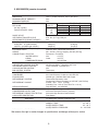
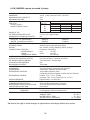
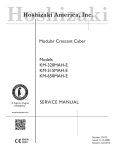
5. KM-1800SRH
(remote air-cooled)
ITEM:
HOSHIZAKI STACKABLE
CRESCENT CUBER
MODEL: KM-1800SRH
AC SUPPLY VOLTAGE
AMPERAGE
MINIMUM CIRCUIT AMPACITY
MAXIMUM FUSE SIZE
APPROXIMATE ICE PRODUCTION
PER 24 HR.
lbs./day ( kg/day )
Reference without *marks
SHAPE OF ICE
ICE PRODUCTION PER CYCLE
APPROXIMATE STORAGE CAPACITY
ELECTRIC & WATER CONSUMPTION
ELECTRIC W (kWH/100 lbs.)
WATER gal./24HR (gal./100 lbs.)
EXTERIOR DIMENSIONS (WxDxH)
EXTERIOR FINISH
WEIGHT
CONNECTIONS - ELECTRIC
- WATER SUPPLY
- DRAIN
- CONDENSATE DRAIN
CUBE CONTROL SYSTEM
HARVESTING CONTROL SYSTEM
ICE MAKING WATER CONTROL
COOLING WATER CONTROL
BIN CONTROL SYSTEM
COMPRESSOR
CONDENSER
EVAPORATOR
REFRIGERANT CONTROL
REFRIGERANT CHARGE
DESIGN PRESSURE
P.C. BOARD CIRCUIT PROTECTION
COMPRESSOR PROTECTION
REFRIGERANT CIRCUIT PROTECTION
LOW WATER PROTECTION
ACCESSORIES -SUPPLIED
-REQUIRED
OPERATING CONDITIONS
DRAWING NO. (DIMENSION)
208-230/60/1 (3 wire with neutral for 115V)
16.5 A ( 5 Min. Freeze AT 104°F / WT 80°F)
30 A
30 A
Ambient
WATER TEMP. (°F)
Temp.(°F)
50
70
90
70
*1817 (824)
1768 (802)
1643 (745)
80
1780 (807)
1704 (773)
1546 (701)
90
1768 (802)
*1651 (749)
1504 (682)
100
1723 (782)
1617 (733)
1369 (621)
Crescent Cube
47.8 lbs. (21.7 kg) 2160 pcs.
N/A
90/70°F
70/50°F
2890(4.2)
2730(3.6)
439(26.6)
721(39.7)
48" x 27 3/8" x 36 7/16" (1219 x 695 x 925 mm)
Stainless Steel, Galvanized Steel (Rear)
Net 344 lbs. (156 kg), Shipping 440 lbs. (200 kg)
Permanent - Connection
Inlet
1/2" FPT
Outlet
3/4" FPT
3/8" OD Pipe
Float Switch
Hot Gas and Water, Thermistor and Timer
Timer Controlled. Overflow Pipe
N/A
Thermostat
Hermetic, Model CS18K6E-PFV
Air-Cooled Remote, Condenser Unit URC-20F
Vertical type, Stainless Steel and Copper
Thermostatic Expansion Valve
Condensing Pressure Regulator on URC-20F (210 PSI Set)
R-404A, 15 lb. 7.0 oz. (7,000g)
(Icemaker 7 lbs. 12.0 oz. Cond. Unit 7 lb. 11.0 oz.)
High 467PSIG, Low 230PSIG
High Voltage Cut-out ( Internal )
Auto-reset Overload Protector ( Internal )
Auto-reset High Pressure Control Switch
Float Switch
N/A
Ice Storage Bin, Remote Condenser Unit
VOLTAGE RANGE
187 - 253 V
AMBIENT TEMP.
45 -100° F
WATER SUPPLY TEMP.
45 - 90° F
WATER SUPPLY PRESSURE
10 - 113 PSIG
3A3453
We reserve the right to make changes in specifications and design without prior notice.
We reserve the right to make changes in specifications and design without prior notice.
APPROVED
9
CHECKED
WRITTEN
TGray
8/26/2005
SPECIFICATION NO. 05A002
ISSUED: 10/3/2005
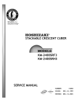
6. KM-1800SRH3
(remote air-cooled,
phase)
ITEM:
HOSHIZAKI STACKABLE
CRESCENT 3
CUBER
MODEL: KM-1800SRH3
AC SUPPLY VOLTAGE
AMPERAGE
MINIMUM CIRCUIT AMPACITY
MAXIMUM FUSE SIZE
APPROXIMATE ICE PRODUCTION
PER 24 HR.
lbs./day ( kg/day )
Reference without *marks
SHAPE OF ICE
ICE PRODUCTION PER CYCLE
APPROXIMATE STORAGE CAPACITY
ELECTRIC & WATER CONSUMPTION
ELECTRIC W (kWH/100 lbs.)
WATER gal./24HR (gal./100 lbs.)
EXTERIOR DIMENSIONS (WxDxH)
EXTERIOR FINISH
WEIGHT
CONNECTIONS - ELECTRIC
- WATER SUPPLY
- DRAIN
- CONDENSATE DRAIN
CUBE CONTROL SYSTEM
HARVESTING CONTROL SYSTEM
ICE MAKING WATER CONTROL
COOLING WATER CONTROL
BIN CONTROL SYSTEM
COMPRESSOR
CONDENSER
EVAPORATOR
REFRIGERANT CONTROL
REFRIGERANT CHARGE
DESIGN PRESSURE
P.C. BOARD CIRCUIT PROTECTION
COMPRESSOR PROTECTION
REFRIGERANT CIRCUIT PROTECTION
LOW WATER PROTECTION
ACCESSORIES -SUPPLIED
-REQUIRED
OPERATING CONDITIONS
DRAWING NO. (DIMENSION)
208-230/60/3
10.9 A ( 5 Min. Freeze AT 104°F / WT 80°F)
20 A
20 A
Ambient
WATER TEMP. (°F)
Temp.(°F)
50
70
90
70
*1775 (805)
1722 (781)
1618 (734)
80
1735 (787)
1653 (750)
1531 (695)
90
1722 (781)
*1595 (723)
1479 (671)
100
1691 (767)
1568 (711)
1372 (622)
Crescent Cube
47.7 lbs. (21.7 kg) 2160 pcs.
N/A
90/70°F
70/50°F
2860(4.3)
2660(3.6)
456(28.6)
774(43.6)
48" x 27 3/8" x 36 7/16" (1219 x 695 x 925 mm)
Stainless Steel, Galvanized Steel (Rear)
Net 344 lbs. (156 kg), Shipping 440 lbs. (200 kg)
Permanent - Connection
Inlet
1/2" FPT
Outlet
3/4" FPT
3/8" OD Pipe
Float Switch
Hot Gas and Water, Thermistor and Timer
Timer Controlled. Overflow Pipe
N/A
Thermostat
Hermetic, Model CS18K6E-TF5
Air-Cooled Remote, Condenser Unit URC-20F
Vertical type, Stainless Steel and Copper
Thermostatic Expansion Valve
Condensing Pressure Regulator on URC-20F (210 PSI Set)
R-404A, 15 lb. 7.0 oz. (7,000g)
(Icemaker 7 lbs. 12.0 oz. Cond. Unit 7 lb. 11.0 oz.)
High 467 PSIG, Low 230 PSIG
High Voltage Cut-out ( Internal )
Auto-reset Overload Protector ( Internal )
Auto-reset High Pressure Control Switch
Float Switch
N/A
Ice Storage Bin, Remote Condenser Unit
VOLTAGE RANGE
187 - 253 V
AMBIENT TEMP.
45 -100° F
WATER SUPPLY TEMP.
45 - 90° F
WATER SUPPLY PRESSURE
10 - 113 PSIG
3A3453
reserve the
the right
changes
in specifications
and design
prior
notice. prior notice.
WeWe
reserve
righttotomake
make
changes
in specifications
andwithout
design
without
APPROVED
10
CHECKED
WRITTEN
TGray
10/3/05
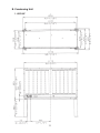
B. Condensing Unit
1. URC-20F
11
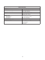
SPECIFICATIONS
MODEL: URC-20F
EXTERIOR
DIMENSIONS (W × D × H)
REFRIGERANT CHARGE
WEIGHT
CONNECTIONS
REFRIGERANT
ELECTRICAL
CONDENSER
HEAD PRESSURE CONTROL
AMBIENT CONDITION
Galvanized Steel
46 - 3/8” × 15 - 11/16” × 25 - 15/16”
(1178 × 398 × 659 mm)
R404A 7 lbs. 11 oz. (3500 g)
Net 104 lbs. (47 kg)
Shipping 150 lbs. (52 kg)
One Shot Couplings (Parker)
Permanent Connection
Air-Cooled
Condensing Pressure Regulator
Min. -20°F to Max. +122°F
(-29°C to +50°C)
Outdoor Use
12
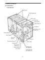
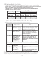
II. General Information
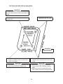
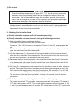
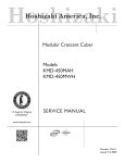
A. Construction
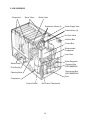
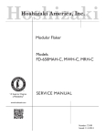
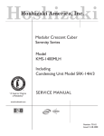
1. KM-1800SAH/3
Spray Tubes
Water Supply Inlet
Water Valve
Hot Gas Valve
Junction Box
Check Valves (3)
Condenser
Condenser Fan
Motors (2)
Water Pump
Float Switch
Interlock
Switch
Drier
Expansion Valves (3)
Line Valve
Compressor
Bin Control
Thermostat
Capacitor Box
(KM-1800SAH)
Control Switch
Control Box
Transformer Box
(KM-1800SAH3)
13
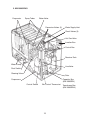
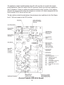
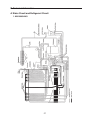
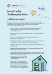
2. KM-1800SWH/3
Evaporator
Spray Tubes
Water Valve
Expansion Valves (3)
Water Supply Inlet
Check Valves (3)
Hot Gas Valve
Junction Box
Control Box
Water-cooled
Condenser
Line Valve
Water Regulator
Water Pump
Capacitor Box
(KM-1800SWH)
Float Switch
Transformer Box
(KM-1800SWH3)
Cleaning Valve
Drier
Compressor
Control Switch
Bin Control Thermostat
14
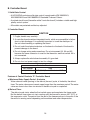
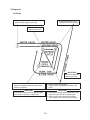
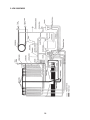
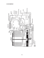
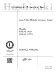
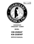
3. KM-1800SRH/3
Evaporator
Spray Tubes
Water Valve
Expansion Valves (3)
Water Supply Inlet
Check Valves (3)
Hot Gas Valve
Junction Box
Control Box
Receiver Tank
Water Pump
Line Valve
Float Switch
Cleaning Valve
Drier
Capacitor Box
(KM-1800SRH)
Compressor
Control Switch
Bin Control Thermostat
15
Transformer Box
(KM-1800SRH3)
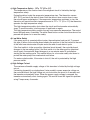
B. Controller Board
1. Solid-State Control
• A HOSHIZAKI exclusive solid-state control is employed in KM-1800SAH/3,
KM-1800SWH/3 and KM-1800SRH/3 Stackable Crescent Cubers.
• A printed circuit board (hereafter called "controller board") includes a stable and high
quality control system.
• All models are pretested and factory-adjusted.
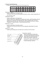
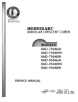
2. Controller Board
CAUTION
1. Fragile, handle very carefully.
2. A controller board contains integrated circuits, which are susceptible to failure
due to static discharge. It is especially important to touch the metal part of
the unit when handling or replacing the board.
3. Do not touch the electronic devices on the board or the back of the board to
prevent damage to the board.
4. Do not change wiring and connections. Do not misconnect K3, K4 and K5,
because the same connector is used for the thermistor and float switch. K4 is
not connected.
5. Always replace the whole board assembly if it goes bad.
6. Do not short out power supply to test for voltage.
Part Number
2A1410-01
Controller Board
Type
HOS-001A (Control Products - 10 Pin)
Features of Control Products "E" Controller Board
a) Maximum Water Supply Period - 6 minutes
Water solenoid valve opening, in the defrost (harvest) cycle, is limited by the defrost
timer. The water valve cannot remain open longer than the maximum period. The water
valve can close in less than six minutes if the defrost cycle is completed.
b) Defrost Timer
The defrost cycle starts when the float switch opens and completes the freeze cycle.
But the defrost timer does not start counting until the thermistor senses 48°F (9°C) at
the evaporator outlet. The period from the end of the freeze cycle up to the point of the
thermistor’s sensing varies depending on the ambient and water temperatures.
16
c) High Temperature Safety - 127 ± 7°F (53 ± 4°C)
The temperature of the suction line in the refrigerant circuit is limited by the high
temperature safety.
During the defrost cycle the evaporator temperature rises. The thermistor senses
48°F (9°C) and starts the defrost timer. After the defrost timer counts down to zero,
the normal freeze cycle begins. If the evaporator temperature continues to rise, the
thermistor will sense the rise in temperature and at 127 ± 7°F (53 ± 4°C) the thermistor
operates the high temperature safety.
This high temperature safety shuts down the circuit and the icemaker automatically
stops. To reset the safety, turn the power off and back on again.
This high temperature safety protects the unit from excessive temperature. The control
board will beep every 3 seconds. The white Reset button on the control board must be
pressed with power on to reset the safety.
d) Low Water Safety
If the pump motor is operated without water, the mechanical seal can fail. To prevent
this type of failure, the controller board checks the position of the float switch at the end
of the initial one minute water fill cycle and at the end of each defrost cycle.
If the float switch is in the up position (electrical circuit closed), the controller board
changes to the ice making cycle. If the float switch is in the down position (electrical
circuit open), the controller board changes to a one minute water fill cycle before
starting the ice making cycle. This method allows for a low water safety shut down to
protect the water pump from mechanical seal failure.
For water-cooled models, if the water is shut off, the unit is protected by the high
pressure switch.
e) High Voltage Cut-out
The maximum allowable supply voltage of this icemaker is limited by the high voltage
cut-out.
If miswiring (especially on single phase 3 wire models) causes excessive voltage on
the controller board, the high voltage cut-out shuts down the circuit in 3 seconds and
the icemaker automatically stops. When the proper supply voltage is resumed, the
icemaker automatically starts running again. The control board will signal this problem
using 7 beeps every 3 seconds.
17
f) LED Lights and Audible Alarm Safeties
The red LED indicates proper control voltage and will remain on unless a control voltage
problem occurs. At startup a 5 second delay occurs while the board conducts an internal timer
check. A short beep occurs when the power switch is turned ON or OFF.
The green LEDs 1-4 represent the corresponding relays and energize and sequence
5 seconds from initial startup as follows:
Sequence Step
Time LEDs are Lit
LED
Min.
1 Minute Fill Cycle 4
Harvest Cycle
Freeze Cycle
1, 4, and 2
1
Reverse Pump Out 1, 3, and 2
2 minutes
5 minutes
Max.
Avg.
60 seconds
20 minutes 3 to 5 minutes
60 minutes 30 to 35 minutes
10 seconds 20 seconds factory setting
{LED 1 – Comp; LED 2 - HGV/CFM; LED 3 – PM; LED 4 - WV}
The built in safeties shut down the unit and have alarms as follows:
No. of Beeps
(every 3 sec.)
Type of Alarm
Notes
1
High Evaporator Temp.
(temperature > 127°F)
(53°C)
Check for defrost problem (stuck HGV
or relay), hot water entering unit, stuck
headmaster, or shorted thermistor.
2
Defrost Backup Timer
(defrost > 20 min.)
Orange LED marked H TIMER lights up.
Check for open thermistor, HGV not
opening, TXV leaking by, low charge, or
inefficient compressor.
3
Freeze Backup Timer
Yellow LED marked F TIMER lights up.
(freeze > 60 min. for
Check for F/S stuck closed (up), WV
KM-1800SWH/3;
leaking by, HGV leaking by, TXV not
freeze > 70 min. for
feeding properly, low charge, or inefficient
KM-1800SAH/3 or
compressor.
KM-1800SRH/3)
To manually reset the above safeties, press the white alarm reset button with the
power supply on.
6
Low Voltage
(92Vac or less)
7
High Voltage
(control voltage
> 147Vac ±5%)
Red LED will turn off if voltage protection
operates.
The voltage safety automatically resets
when voltage is corrected.
The output test switch "S3" provides a relay sequence test. With power OFF, place S3 ON and
switch power to ICE. The correct lighting sequence should be none, 2, 3, 4, 1, & 4, normal
sequence every 5 seconds. S3 should remain in the "OFF" position for normal operation.
18
The application switch located between relay X3 & X4 must be set to match the original
board application. Place this switch in the ALP position if there is no white wire supplied to
the K1 connector. If there is a white wire, place the switch in the C position. If this switch is
placed in the wrong position either the compressor contactor will remain energized with the
control switch OFF or the unit will not start.
The dip switches should be adjusted per the adjustment chart published in the Tech Specs
book. 7 & 8 must remain in the OFF position.
(Control Products HOS-001A Board)
19
3. Sequence
1st Cycle
1. Unit energized and control switch to "ICE"
position. Water supply cycle starts.
3. Thermistor reads 48°F (9°C).
Defrost timer starts counting.
2. After 1 minute.
Defrost cycle starts.
IMPORTANT
Water valve opening is
limited to 6 minutes.
5. After the first 5 minutes in freeze cycle.
Ready to complete freeze cycle when float
switch circuit opens.
4. Defrost timer stops counting.
Defrost cycle is completed and freeze cycle
starts.
IMPORTANT
1. Board never accepts defrost completion signal
within the first 2 minutes in defrost cycle.
2. Defrost cycle time is limited to 20 minutes
even if defrost timer does not stop counting.
IMPORTANT
Board never accepts freeze completion signal
within the first 5 minutes in freeze cycle.
20
2nd Cycle and after with pump drain
IMPORTANT
Freeze cycle time is limited by the freeze timer
factory setting even if the float switch does not
open.
2. Drain timer stops counting.
Pump drain is completed.
1. Float switch opens and signals to complete
freeze cycle.
Drain timer starts counting.
3. Thermistor reads 48°F (9°C).
Defrost timer starts counting.
IMPORTANT
Water valve opening is
limited to 6 minutes.
5. After the first 5 minutes in freeze cycle.
Ready to complete freeze cycle when float
switch circuit opens.
4. Defrost timer stops counting.
Defrost cycle is completed and freeze cycle
starts.
IMPORTANT
Board never accepts freeze completion signal
within the first 5 minutes in freeze cycle.
21
IMPORTANT
1. Board never accepts defrost completion
signal within the first 2 minutes in defrost
cycle.
2. Defrost cycle time is limited to 20 minutes
even if defrost timer does not stop counting.
2nd Cycle and after with no pump drain
IMPORTANT
Freeze cycle time is limited by the freeze timer
factory setting even if the float switch does not
open.
2. Thermistor reads 48°F (9°C).
Defrost timer starts counting.
1. Float switch opens and signals to complete
freeze cycle.
IMPORTANT
Water valve opening is
limited to 6 minutes.
4. After the first 5 minutes in freeze cycle.
Ready to complete freeze cycle when float
switch circuit opens.
IMPORTANT
Board never accepts freeze completion signal
within the first 5 minutes in freeze cycle.
3. Defrost timer stops counting.
Defrost cycle is completed and freeze cycle
starts.
IMPORTANT
1. Board never accepts defrost completion
signal within the first 2 minutes in defrost
cycle.
2. Defrost cycle time is limited to 20 minutes
even if defrost timer does not stop counting.
22
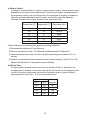
4. Controls and Adjustments
The dip switch is factory-adjusted to the following positions:
Dip Switch No.
4
5
KM-1800SAH/3
OFF OFF ON
1
2
3
ON
ON
ON OFF OFF ON OFF
KM-1800SWH/3
OFF OFF ON
ON
ON
ON OFF OFF OFF OFF
KM-1800SRH/3
OFF ON
ON
ON
ON OFF OFF ON OFF
ON
6
7
8
9
10
Switch Nos. 1 and 2:
Used for adjustment of the defrost timer.
The defrost timer starts counting when the thermistor reads a certain temperature at
the evaporator outlet.
Switch Nos. 3 and 4:
Used for adjustment of the drain timer.
When a freeze cycle is completed, the pump motor stops, and the icemaker resumes
operation in 2 seconds. Then the pump motor drains the water tank for the time
determined by the drain timer. The drain timer also determines the time to restrain
completion of a defrost cycle, i.e. the minimum defrost time.
Switch Nos. 5 and 6:
Used for adjustment of the drain counter.
The pump motor drains the water tank at the frequency determined by the drain
counter.
Switch Nos. 7 and 8:
Used only for checking the controller board. Usually set in OFF position.
Switch Nos. 9 and 10:
Used for adjustment of freeze timer.
The freeze timer determines maximum
freeze cycle time. Upon termination of
freeze timer, machine initiates the
harvest cycle. After 2 consecutive timer
terminations, machine will shut down,
possibly indicating a problem.
23
a) Defrost Control
A thermistor (semiconductor) is used for a defrost control sensor. The resistance varies
depending on the suction line temperatures. The thermistor detects the temperature of
the evaporator outlet to start the defrost timer. No adjustment is required. If necessary,
check for resistance between thermistor leads, and visually check the thermistor
mounting, located on the suction line next to the evaporator outlet.
Temperature (°F) Temperature (°C)
0
10
32
50
70
90
-18
-12
0
10
21
32
Resistance (kΩ)
14.401
10.613
6.000
3.871
2.474
1.633
Check a thermistor for resistance by using the following procedure:
1) Disconnect the connector K3 on the board.
2) Remove the thermistor. See "V.H. Removal and Replacement of Thermistor."
3) Immerse the thermistor sensor portion in a glass containing ice and water for 2 or 3
minutes.
4) Check for a resistance between thermistor leads. Normal reading is within 3.5 to 7 kΩ.
Replace the thermistor if it exceeds the normal reading.
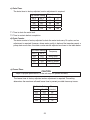
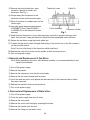
b) Defrost Timer
No adjustment is required under normal use, as the defrost timer is adjusted to the
suitable position. However, if necessary when all the ice formed on the evaporator does
not fall into the bin in the harvest cycle, adjust the defrost timer to longer setting by
adjusting the dip switch (No. 1 & 2) on the controller board.
Dip Switch Setting
Time
No. 1
No. 2 (seconds)
OFF
OFF
60
ON
OFF
90
OFF
ON
120
ON
ON
180
24
c) Drain Timer
The drain timer is factory-adjusted, and no adjustment is required.
Dip Switch Setting
No. 3
OFF
ON
OFF
ON
Time (seconds)
T1
No. 4
OFF
OFF
ON
ON
T2
150
180
120
180
10
10
10
20
T1: Time to drain the water tank
T2: Time to restrain defrost completion
d) Drain Counter
The drain counter is factory-adjusted to drain the water tank every 10 cycles, and no
adjustment is required. However, where water quality is bad and the icemaker needs a
pump drain more often, the drain counter can be adjusted as shown in the table below:
Dip Switch Setting
No. 5
OFF
ON
OFF
ON
No. 6
OFF
OFF
ON
ON
Frequency
every cycle
every 2 cycles
every 5 cycles
every 10 cycles
e) Freeze Timer
CAUTION
Adjust to proper specification, or the unit may not operate correctly.
The freeze timer is factory adjusted and no adjustment is required. The setting
determines the maximum allowed freeze time to prevent possible freeze-up issues.
Dip Switch Setting
No. 9
OFF
OFF
ON
ON
No. 10
ON
OFF
ON
OFF
25
Time
(minutes)
50
60
60
70
f) Bin Control
CAUTION
When the ambient temperature is below 45°F (7°C), the bin control thermostat
operates to stop the icemaker even if the ice storage bin is empty. When the
thermostat is set in the prohibited range, the icemaker operates continuously
even if the ice storage bin is filled with ice. Setting in the prohibited range might
cause severe damage to the icemaker resulting in failure.
No adjustment is required under normal use, as the bin control is factory-adjusted.
Adjust it, if necessary, so that the icemaker stops automatically within 10 seconds after
ice contacts the bin control thermostat bulb.
5. Checking the Controller Board
a) Visually check the sequence with the icemaker operating.
b) Visually check the controller board by using the following procedure:
1) Adjust the defrost timer to minimum position.
Disconnect the thermistor from the controller board.
Connect a 1.5 to 3.5 kΩ resistor to connector K3 (pins #1 and #2), and energize the
unit.
After the 1 minute ± 5 second water supply cycle and the 2 minute ± 10 second defrost
cycle, the unit should start the freeze cycle.
2) After the above step 1), disconnect the float switch leads from the controller board
within the first 5 minutes of the freeze cycle. The unit should go into the defrost cycle
after the first 5 minutes ± 20 seconds of the freeze cycle.
3) Reconnect the float switch connector to the controller board. After the first 5 minutes
of the freeze cycle, disconnect the float switch leads from the controller board. At this
point, the unit should start the defrost cycle.
4) After step 3), de-energize the unit and confirm that the defrost timer is in the minimum
position. Disconnect the resistor from the controller board and energize the unit. After
the 1 minute water supply cycle, the defrost cycle starts. Re-connect a 1.5 to 3.5 kΩ
resistor to connector K3 (pins #1 and #2) after the first 2 minutes of the defrost cycle.
The unit should start the freeze cycle after 1 minute ± 5 seconds from the resistor
connection.
c) Check the controller board using the controller board’s test program.
The output test switch "S3" provides a relay sequence test. With power OFF, place S3
"ON" and switch power to "ICE". The correct lighting sequence should be none, 2, 3, 4,
1, and 4, normal sequence every 5 seconds. S3 should remain in the "OFF" position for
normal operation.
26
III. Technical Information
A. Water Circuit and Refrigerant Circuit
1. KM-1800SAH/3
27
2. KM-1800SWH/3
28
3. KM-1800SRH/3
29
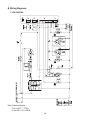
B. Wiring Diagrams
1. KM-1800SAH
Note: Pressure Switch
Cut-out 412 +21.3
PSIG
0
Cut-in 327 ± 21.3 PSIG
30
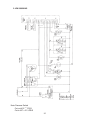
2. KM-1800SAH3
Note: Pressure Switch
Cut-out 412 +21.3
PSIG
0
Cut-in 327 ± 21.3 PSIG
31
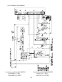
3. KM-1800SWH, KM-1800SRH
Note: Pressure Switch KM-1800SRH
Cut-out 412 +21.3
PSIG
0
Cut-in 327 ± 21.3 PSIG
Note: Pressure Switch KM-1800SWH
Cut-out 384 +21.3
PSIG
0
Cut-in 284 ± 21.3 PSIG
32
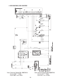
4. KM-1800SWH3, KM-1800SRH3
Note: Pressure Switch KM-1800SRH3
Cut-out 412 +21.3
PSIG
0
Cut-in 327 ± 21.3 PSIG
Note: Pressure Switch KM-1800SWH3
Cut-out 384 +21.3
PSIG
0
Cut-in 284 ± 21.3 PSIG
33
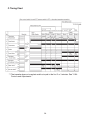
C. Timing Chart
*1 The icemaker does not complete a defrost cycle in the first 2 or 3 minutes. See "II.B.4.
Controls and Adjustments."
34
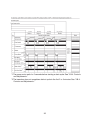
*1 The pump motor waits for 2 seconds before starting a drain cycle. See "II.B.4. Controls
and Adjustments."
*2 The icemaker does not complete a defrost cycle in the first 2 or 3 minutes. See "II.B.4.
Controls and Adjustments."
35
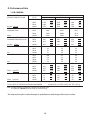
D. Performance Data
1. KM-1800SAH
APPROXIMATE ICE
PRODUCTION PER 24 HR.
WATER TEMP. (ºF/ºC)
AMBIENT TEMP.
(ºF/ºC)
50/10
70/21
90/32
70/21
80/27
1756
1702
797
772
1685
1592
764
722
1589
1496
721
679
lbs./day kg./day
90/32
100/38
1685
1579
764
716
1514
1491
687
676
1416
1326
642
601
APPROXIMATE ELECTRIC
CONSUMPTION
70/21
80/27
2780
2825
2838
2915
2881
2937
watts
APPROXIMATE WATER
CONSUMPTION PER 24 HR.
90/32
100/38
70/21
80/27
680
606
2838
2910
2979
2986
3010
3039
90/32
100/38
70/21
80/27
3
gal./day m /day
FREEZING CYCLE TIME
min.
HARVEST CYCLE TIME
min.
HEAD PRESSURE
PSIG
kg/cm 2G
SUCTION PRESSURE
PSIG
kg/cm 2G
2.57
2.29
583
455
583
2.21
456
1.73
2.21
1.72
496
394
1.88
1.49
348
1.32
275
1.04
331
1.25
207
0.78
31
33
33
36
36
39
90/32
100/38
70/21
33
37
6.0
39
40
5.3
42
45
4.6
80/27
90/32
5.4
5.3
4.3
3.5
3.9
3.0
100/38
70/21
80/27
90/32
4.2
3.4
2.5
230
246
251
16.2
17.3
17.6
251
278
300
17.6
19.5
21.1
277
303
326
19.4
21.3
22.9
100/38
255
17.9
306
21.5
350
24.6
70/21
80/27
90/32
50
51
51
3.5
3.6
3.6
51
53
55
3.6
3.8
3.9
54
56
58
3.8
3.9
4.1
100/38
52
3.7
56
3.9
60
4.2
TOTAL HEAT OF REJECTION FROM CONDENSER
24720 BTU/h [AT 90ºF (32ºC) / WT 70ºF (21ºC)]
Note: Pressure data is recorded at 5 minutes into freezing cycle.
The data not in bold should be used for reference only.
We reserve the right to make changes in specifications and design without prior notice.
36
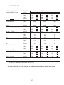
2. KM-1800SAH3
APPROXIMATE ICE
PRODUCTION PER 24 HR.
lbs./day kg./day
WATER TEMP. (ºF/ºC)
AMBIENT TEMP.
(ºF/ºC)
50/10
70/21
90/32
70/21
80/27
1757
1701
797
772
1683
1587
764
720
1597
1507
724
684
90/32
100/38
1683
1579
764
716
1506
1486
683
674
1422
1344
645
610
APPROXIMATE ELECTRIC
CONSUMPTION
70/21
80/27
90/32
2562
2649
2676
2676
2825
2949
2763
2875
3017
watts
APPROXIMATE WATER
CONSUMPTION PER 24 HR.
100/38
70/21
80/27
694
612
2818
2965
3080
90/32
587
100/38
70/21
80/27
454
3
gal./day m /day
FREEZING CYCLE TIME
min.
HARVEST CYCLE TIME
min.
HEAD PRESSURE
PSIG
kg/cm 2G
SUCTION PRESSURE
PSIG
kg/cm 2G
2.63
2.32
587
446
2.22
328
1.72
314
2.22
1.69
508
405
1.24
269
1.19
215
1.92
1.53
1.02
0.81
32
34
34
37
37
40
90/32
100/38
70/21
34
38
6.0
40
41
5.1
43
45
4.6
80/27
90/32
5.3
5.1
4.0
3.0
3.9
2.7
100/38
70/21
80/27
90/32
240
257
262
16.9
18.1
18.4
262
291
315
18.4
20.5
22.1
283
306
333
19.9
21.5
23.4
100/38
291
20.5
319
22.4
350
24.6
70/21
80/27
90/32
52
53
53
3.7
3.7
3.7
53
54
55
3.7
3.8
3.9
55
57
58
3.9
4.0
4.1
100/38
54
3.8
56
3.9
60
4.2
4.1
2.5
2.9
TOTAL HEAT OF REJECTION FROM CONDENSER
24150 BTU/h [AT 90ºF (32ºC) / WT 70ºF (21ºC)]
Note: Pressure data is recorded at 5 minutes into freezing cycle.
The data not in bold should be used for reference only.
We reserve the right to make changes in specifications and design without prior notice.
37
3. KM-1800SWH
No Data Available
We reserve the right to make changes in specifications and design without prior notice.
38
4. KM-1800SWH3
No Data Available
We reserve the right to make changes in specifications and design without prior notice.
39
PERFORMANCE DATA NO. 05A001
ITEM: HOSHIZAKI STACKABLE CRESCENT CUBER
ISSUED:
08/26/05
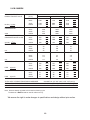
5. KM-1800SRH
MODEL: KM-1800SRH
APPROXIMATE ICE
PRODUCTION PER 24 HR.
lbs./day kg./day
APPROXIMATE ELECTRIC
CONSUMPTION
WATER TEMP. (ºF/ºC)
AMBIENT TEMP.
(ºF/ºC)
50/10
1817
1780
824
807
1768
1704
802
773
1643
1546
745
701
90/32
100/38
70/21
80/27
1768
1723
802
782
1651
1617
749
733
1504
1369
682
621
watts
APPROXIMATE WATER
CONSUMPTION PER 24 HR.
100/38
70/21
80/27
90/32
721
658
639
gal./day m3/day
FREEZING CYCLE TIME
100/38
528
min.
HEAD PRESSURE
PSIG
kg/cm2G
SUCTION PRESSURE
PSIG
2
kg/cm G
90/32
70/21
80/27
90/32
min.
HARVEST CYCLE TIME
70/21
2730
2766
2777
2839
2823
2875
2777
2890
2932
2780
2.73
2.49
2.42
639
530
439
2.00
422
2900
2.42
2.01
1.66
557
466
366
1.60
298
2970
2.11
1.76
1.38
1.13
70/21
80/27
32
33
34
36
37
39
90/32
100/38
70/21
34
35
5.4
38
39
4.9
41
44
4.4
80/27
90/32
5.0
4.9
4.2
3.7
3.8
3.2
2.8
100/38
70/21
80/27
90/32
220
226
227
15.5
15.9
16.0
227
237
245
16.0
16.7
17.2
247
262
268
17.4
18.4
18.9
100/38
235
16.5
250
17.6
290
20.4
70/21
80/27
90/32
40
41
41
2.8
2.9
2.9
41
43
45
2.9
3.1
3.2
44
46
48
3.1
3.2
3.3
100/38
42
3.0
46
3.2
50
3.5
4.2
TOTAL HEAT OF REJECTION FROM CONDENSER
TOTAL HEAT OF REJECTION FROM COMPRESSOR
CONDENSER VOLUME
3.6
24,600 BTU/h [AT 90ºF (32ºC) / WT 70ºF (21ºC)]
3,300 BTU/h [AT 90ºF (32ºC) / WT 70ºF (21ºC)]
214 CU. IN (URC-20F)
Note: Pressure data is recorded at 5 minutes into freezing cycle.
The data not in bold should be used for reference only.
We reserve the right to make changes in
We reserve the right to make changes
specifications and design without prior notice.
in specifications and design without prior notice.
APPROVED
CHECKED
WRITTEN
TGray
8/26/2005
40
ENG.F-011.1.0205
PERFORMANCE DATA NO. 05A002
ITEM: HOSHIZAKI STACKABLE CRESCENT CUBER
ISSUED:
10/03/05
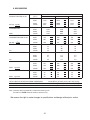
6. KM-1800SRH3
MODEL: KM-1800SRH3
APPROXIMATE ICE
PRODUCTION PER 24 HR.
lbs./day kg./day
APPROXIMATE ELECTRIC
CONSUMPTION
WATER TEMP. (ºF/ºC)
AMBIENT TEMP.
(ºF/ºC)
50/10
805
787
1722
1653
781
750
1618
1531
734
695
90/32
100/38
70/21
80/27
1722
1691
781
767
1595
1568
723
711
1479
1372
671
622
watts
APPROXIMATE WATER
CONSUMPTION PER 24 HR.
100/38
70/21
80/27
90/32
774
703
681
gal./day m3/day
FREEZING CYCLE TIME
100/38
556
min.
HEAD PRESSURE
PSIG
kg/cm2G
SUCTION PRESSURE
PSIG
2
kg/cm G
90/32
1775
1735
90/32
min.
HARVEST CYCLE TIME
70/21
70/21
80/27
2660
2705
2719
2796
2780
2847
2719
2860
2917
2725
2.93
2.66
2.58
681
558
456
2.11
437
2873
2.58
2.11
1.73
591
489
376
1.66
302
2970
2.24
1.85
1.42
1.14
70/21
80/27
32
33
34
37
37
40
90/32
100/38
70/21
34
35
5.8
39
39
5.1
42
45
4.6
80/27
90/32
5.3
5.1
4.3
3.6
4.0
3.2
2.8
100/38
70/21
80/27
90/32
225
231
232
15.8
16.2
16.3
232
242
250
16.3
17.0
17.6
242
252
260
17.0
17.7
18.3
100/38
234
16.5
252
17.7
270
19.0
70/21
80/27
90/32
43
44
44
3.0
3.1
3.1
44
46
48
3.1
3.3
3.4
46
48
50
3.3
3.4
3.5
100/38
45
3.2
48
3.4
52
3.7
4.3
TOTAL HEAT OF REJECTION FROM CONDENSER
TOTAL HEAT OF REJECTION FROM COMPRESSOR
CONDENSER VOLUME
3.5
25,400 BTU/h [AT 90ºF (32ºC) / WT 70ºF (21ºC)]
3,300 BTU/h [AT 90ºF (32ºC) / WT 70ºF (21ºC)]
214 CU. IN (URC-20F)
Note: Pressure data is recorded at 5 minutes into freezing cycle.
The data not in bold should be used for reference only.
We reserve the right to make changes in
We reserve the right to make changes
specifications and design without prior notice.
in specifications and design without prior notice.
APPROVED
CHECKED
WRITTEN
TGray
10/3/2005
41
ENG.F-011.1.0205
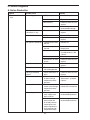
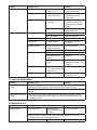
IV. Service Diagnosis
A. No Ice Production
Problem
Possible Cause
[1] The icemaker will not a)Power Supply
start.
Remedy
1. OFF position.
1. Move to ON position.
2. Loose connection.
2. Tighten.
3. Bad contacts.
3. Check for continuity and
replace.
4. Voltage too high.
4. Check and get
recommended voltage.
b)Fuse (Inside fused
disconnect, if any)
1. Blown out.
1. Check for short circuit and
replace.
c) Control Switch
1. OFF position.
1. Move to ICE position.
2. Bad contacts.
2. Check for continuity and
replace.
d)Bin Control Thermostat 1. Tripped with bin filled
with ice.
1. Remove ice.
2. Ambient temperature
too cool.
2. Increase ambient
temperature.
3. Set too warm.
3. See "II.B.4. Controls
and Adjustments, f) Bin
Control."
4. Bulb out of position.
4. Place in position.
5. Bad contacts or leaks 5. Check for continuity and
in bulb.
replace.
e)High Pressure Control
1. Bad contacts.
1. Check for continuity and
replace.
f) Transformer
1. Thermal fuse blown or 1. Replace.
coil winding opened.
g)Wiring to Controller
Board
1. Loose connections or 1. Check for continuity and
open.
replace.
h)Thermistor
1. Leads short-circuit
or open and high
temperature safety
operates.
1. See "II.B.4. Controls and
Adjustments, a) Defrost
Control."
i) Hot Gas Solenoid Valve 1. Continues to open in 1. Check for power off in
freeze cycle and high
freeze cycle and replace.
temperature safety
operates.
j) Water Supply Line
1. Water supply off and
water supply cycle
does not finish.
1. Check and get
recommended pressure.
2. Condenser water
pressure too low
or off and pressure
control opens and
closes frequently to
finally operate high
temperature safety.
2. Check and get
recommended pressure.
42
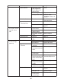
Problem
Possible Cause
k) Water Solenoid
Remedy
1. Mesh filter or orifice
gets clogged and
water supply cycle
does not finish.
1. Clean.
2. Coil winding opened.
2. Replace.
3. Wiring to water valve. 3. Check for loose
connection or open, and
replace.
[2] Water continues to
be supplied, and the
icemaker will not
start.
[3] Compressor will
not start or stops
operating.
l) Controller Board
1. Defective.
1. See "II.B.5. Checking the
Controller Board."
m)Interlock Switch
(Cleaning Valve)
1. OFF Position
1. Move to ON position.
2. Bad contacts.
2. Check for continuity and
replace.
1. Connector
disconnected.
1. Place in position.
2. Leads opened or
defective switch.
2. Check and replace.
3. Float does not move
freely.
3. Clean or replace.
b)Controller Board
1. Defective.
1. Replace.
c) Contactor
1. Open coil or contacts
worn.
1. Replace.
a)Wash Switch
1. WASH position.
1. Move to ICE position.
2. Bad contacts.
2. Check and replace.
1. Dirty air filter or
condenser.
1. Clean.
a)Float Switch
b)High Pressure
Controller
2. Ambient or condenser 2. Reduce temperature.
water temperature too
warm.
3. Refrigerant
overcharged.
3. Recharge.
4. Condenser water
4. Check and get
pressure too low or off. recommended pressure.
[Water-cooled model
only.]
5. Fan not operating.
[Except water-cooled
model.]
5. See chart A.[6]
6. Refrigerant line or
6. Clean and replace drier.
components plugged.
c) Overload Protector
1. Bad contacts.
1. Check for continuity and
replace.
2. Voltage too low.
2. Increase voltage.
3. Refrigerant
overcharged or
undercharged.
3. Recharge.
43
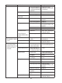
Problem
Possible Cause
Remedy
4. Line valve continues 4. Check line valve’s
to close in freeze cycle operation in freeze cycle
and overload protector and replace.
operates.
d)Starter
1. Bad contacts.
1. Check and replace.
2. Coil winding opened.
2. Replace.
e)Start Capacitor or Run 1. Defective.
Capacitor
1. Replace.
f) Magnetic Contactor
1. Bad contacts.
1. Check for continuity and
replace.
2. Coil winding opened.
2. Replace.
g)Compressor
1. Wiring to compressor. 1. Check for loose
connection or open, and
replace.
2. Defective.
2. Replace.
3. Protector tripped.
3. Reduce temperature.
h)Controller Board
1. Defective.
1. See "II.B.5. Checking the
Controller Board."
i) Water Regulator
[Water-cooled model
only.]
1. Set too high.
1. Adjust lower.
[4] Water continues to
a)Water Solenoid Valve
be supplied in freeze
cycle.
b)Controller Board
1. Diaphragm does not
close.
1. Check for water leaks with
icemaker off.
1. Defective.
1. See "II.B.5. Checking the
Controller Board."
[5] No water comes from a)Water Supply Line
spray tubes. Water
pump will not start, or
freeze cycle time is
b)Water Solenoid Valve
too short.
1. Water pressure too
1. Check and get
low and water level in
recommended pressure.
water tank too low.
c) Water System
1. Dirty mesh filter or
1. Clean.
orifice and water level
in water tank too low.
1. Water leaks.
1. Check connections for
water leaks, and replace.
2. Clogged.
2. Clean.
3. Pump out check valve 3. Check assembly and
leaking by.
clean.
d)Pump Motor
1. Motor winding opened. 1. Replace.
2. Bearing worn out.
2. Replace.
3. Wiring to pump motor. 3. Check for loose
connection or open, and
replace.
4. Defective capacitor.
4. Replace.
5. Defective or bound
impeller.
5. Replace and clean.
6. Mechanical seal worn 6. Check and replace.
out.
e)Controller Board
1. Defective.
44
1. See "II.B.5. Checking the
Controller Board."
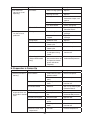
Problem
Possible Cause
[6] Fan motor will
not start, or is not
operating.
a)Fan Motor
[7] All components
run, but no ice is
produced.
Remedy
1. Motor winding opened. 1. Replace.
2. Bearing worn out.
2. Replace.
3. Wiring to fan motor.
3. Check for loose
connection or open, and
replace.
4. Defective capacitor.
4. Replace.
5. Fan blade bound.
5. Check and replace.
b)Controller Board
1. Defective.
1. See "II.B.5. Checking the
Controller Board."
a)Refrigerant
1. Undercharged.
1. Check for leaks and
recharge.
2. Air or moisture
trapped.
2. Replace drier and
recharge.
1. Defective valve.
1. Replace.
b)Compressor
c) Hot Gas Solenoid Valve 1. Continues to open in
freeze cycle.
1. Check and replace.
d)Line Valve
1. Continues to close in
freeze cycle.
1. Check and replace.
e)Water Solenoid Valve
1. Water solenoid valve
is wide open during
freeze.
1. Check for water leaks with
icemaker off.
f) Water Supply Line
[Water-cooled model
only.]
1. Condenser water
1. Check and get
pressure too low or off
recommended pressure.
and pressure control
opens and closes
frequently.
B. Evaporator is Frozen Up
Problem
Possible Cause
[1]Freeze cycle time is
too long.
a) Float Switch
Remedy
1. Leads short-circuit or
defective switch.
1. Check and replace.
2. Float does not move
freely.
2. Clean or replace.
b) Water Solenoid Valve
1. Diaphragm does not
close.
1. Check for water leaks with
icemaker off.
c) Controller Board
1. Defective.
1. See "II.B.5. Checking the
Controller Board."
1. Scaled up.
1. Clean.
1. Water pressure too
low.
1. Check and get
recommended pressure.
1. Dirty/Restricted
1. Replace filter.
1. Dirty mesh filter or
orifice.
1. Clean.
2. Diaphragm does not
close.
2. Check for water leaks with
icemaker off.
1. Too cool.
1. Increase temperature.
[2]All ice formed on
a) Evaporator
evaporator does not b) Water Supply Line
fall into bin in harvest
cycle.
c) Water Filter System
d) Water Solenoid Valve
e) Ambient and/or water
temperature.
45
Problem
[3]Other
Possible Cause
Remedy
f) Line Valve
1. Continues to open in
harvest cycle.
1. Check operation in harvest
cycle and replace.
g) Thermistor
1. Out of position or
loose attachment.
1. See "V.H. Removal
and Replacement of
Thermistor."
h) Controller Board
1. Defrost timer is set
too short.
1. Adjust longer, referring
to "II.B.4. Controls and
Adjustments, b) Defrost
Timer.
2. Defective.
2. See "II.B.5. Checking the
Controller Board."
1. Clogged.
1. Clean
2. Out of position.
2. Place in position.
b) Water System
1. Dirty.
1. Clean.
c) Refrigerant
1. Undercharged.
1. Check for leaks and
recharge.
d) Expansion Valve
1. Bulb out of position or 1. Place in position.
loose attachment.
a) Spray Tubes
2. Defective.
e) Hot Gas Solenoid Valve 1. Coil winding opened.
2. Replace.
1. Replace.
2. Plunger does not
move.
2. Replace.
3. Wiring to hot gas
valve.
3. Check for loose
connection or open, and
replace.
f) Water Supply Line
1. Too small; requires
1. Increase water line size.
1/2" OD line dedicated
per machine.
g) Water Filter
1. Flow rate too small.
1. Replace with filter that has
larger flow rate.
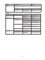
C. Low Ice Production
Problem
Possible Cause
Remedy
[1] Freeze cycle time is
long.
a) See chart A.[3] and check dirty air filter or condenser, ambient or water
temperature, water pressure, water regulator, and refrigerant charge.
b) See chart B.[1] and check float switch, water solenoid valve and controller
board.
[2] Harvest cycle time is a) See chart B.[2] and check controller board, thermistor, evaporator, ambient
long.
and/or water temperature, water supply line, water solenoid valve, line valve,
and hot gas valve.
D. Abnormal Ice
Problem
Possible Cause
[1] Small cubes.
a) Ice Cube Guide
Remedy
1. Out of position.
Circulated water falls
into bin.
1. Place in position.
b) See chart A.[5] and check water supply line, water solenoid valve, water
system, pump motor, and controller board.
c) Pump Out Check Valve 1. Dirty.
46
1. Clean.
Problem
Possible Cause
Remedy
[2] Cloudy or irregular
cubes.
a) See chart B.[1] and B.[3], and check float switch, water solenoid valve,
controller board, spray tubes, water system, refrigerant charge, and expansion
valve.
b) Spray Guide
1. Dirty.
1. Clean.
c) Water Quality
1. High hardness or
contains impurities.
1. Install a water softener or
filter.
E. Other
Problem
Possible Cause
Remedy
[1] Icemaker will not stop a) Bin Control Thermostat 1. Set too cold.
when bin is filled with
2. Defective.
ice.
1. Adjust warmer.
[2] Abnormal noise.
a) Pump Motor
1. Bearings worn out.
1. Replace
b) Fan Motor
1. Bearings worn out.
1. Replace
2. Fan blade deformed.
2. Replace fan blade.
3. Fan blade does not
move freely.
3. Replace.
c) Compressor
[3] Ice in storage bin
often melts.
2. Replace
1. Bearings worn out or 1. Replace.
cylinder valve broken.
2. Mounting pad out of
position.
2. Reinstall.
d) Refrigerant Lines
1. Rub or touch other
lines or surfaces.
1. Replace.
a) Bin Drain
1. Plugged.
1. Clean.
b) Icemaker and Bin
1. Drains not run
separately.
1. Separate the drain lines.
47
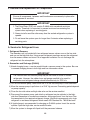
V. Removal and Replacement of Components
IMPORTANT
Ensure all components, fasteners and thumbscrews are securely in place after
the equipment is serviced.
IMPORTANT
1. The Polyol Ester (POE) oils used in R-404A units can absorb moisture
quickly. Therefore it is important to prevent moisture from entering the
system when replacing or servicing parts.
2. Always install a new filter drier every time the sealed refrigeration system is
opened.
3. Do not leave the system open for longer than 5 minutes when replacing or
servicing parts.
A. Service for Refrigerant Lines
1. Refrigerant Recovery
The icemaker unit is provided with two refrigerant access valves–one on the low-side
and one on the high-side line. Using proper refrigerant practices recover the refrigerant
from the access valves and store it in an approved container. Do not discharge the
refrigerant into the atmosphere.
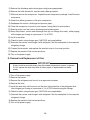
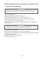
2. Evacuation and Recharge [R-404A]
1) Attach charging hoses, a service manifold and a vacuum pump to the system. Be sure
to connect charging hoses to both high and low side access valves.
IMPORTANT
The vacuum level and vacuum pump may be the same as those for current
refrigerants. However, the rubber hose and gauge manifold to be used for
evacuation and refrigerant charge should be exclusively for POE oils.
2) Turn on the vacuum pump. Never allow the oil in the vacuum pump to flow backward.
3) Allow the vacuum pump to pull down to a 29.9" Hg vacuum. Evacuating period depends
on pump capacity.
4) Close the low-side valve and high-side valve on the service manifold.
5) Disconnect the vacuum pump, and attach a refrigerant service cylinder to the highside line. Remember to loosen the connection, and purge the air from the hose. See
the nameplate for the required refrigerant charge. Hoshizaki recommends only virgin
refrigerant or reclaimed refrigerant which meets ARI Standard No. 700-88 be used.
6) A liquid charge is recommended for charging an R-404A system. Invert the service
cylinder. Open the high-side, service manifold valve.
7) Allow the system to charge with liquid until the pressures balance.
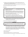
48
8) If necessary, add any remaining charge to the system through the low-side. Use a
throttling valve or liquid dispensing device to add the remaining liquid charge through
the low-side access port with the unit running.
9) Close the two refrigerant access valves, and disconnect the hoses and service manifold.
10) Cap the access valves to prevent a possible leak.
B. Brazing
DANGER
1. Refrigerant R-404A itself is not flammable at atmospheric pressure and
temperatures up to 176° F.
2. Refrigerant R-404A itself is not explosive or poisonous. However, when
exposed to high temperatures (open flames) R-404A can be decomposed to
form hydrofluoric acid and carbonyl fluoride both of which are hazardous.
3. Always recover the refrigerant and store it in an approved container. Do not
discharge the refrigerant into the atmosphere.
4. Do not use silver alloy or copper alloy containing arsenic.
5. Do not use R-404A as a mixture with pressurized air for leak testing.
Refrigerant leaks can be detected by charging the unit with a little refrigerant,
raising the pressure with nitrogen and using an electronic leak detector.
Note: All brazing-connections inside the Evaporator Case are clear-paint coated.
Sandpaper the brazing connections before unbrazing the components. Use a
good abrasive cloth to remove coating.
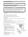
C. Removal and Replacement of Compressor
IMPORTANT
Always install a new drier every time the sealed refrigeration system is opened.
Do not replace the drier until after all other repair or replacement has been
made.
Note: When replacing a compressor with a defective winding, be sure to install the
new start capacitor and start relay supplied with the replacement compressor.
Due to the ability of the POE oil in the compressor to absorb moisture quickly,
the compressor must not be opened more than 15 minutes for replacement or
service. Do not mix lubricants of different compressors even if both are charged
with R-404A, except when they use the same lubricant.
1) Turn off the power supply.
2) Remove the panels.
3) Recover the refrigerant and store it in an approved container.
4) Remove the terminal cover on the compressor, and disconnect the compressor wiring.
49
5) Remove the discharge and suction pipes using brazing equipment.
6) Remove the hold-down bolts, washers and rubber grommets.
7) Slide and remove the compressor. Unpack the new compressor package. Install the new
compressor.
8) Attach the rubber grommets of the prior compressor.
9) Sandpaper the suction, discharge and process pipes.
10) Place the compressor in position, and secure it using the bolts and washers.
11) Remove plugs from the suction, discharge and process pipes.
12) Braze the process, suction and discharge lines (do not change this order), while purging
with nitrogen gas flowing at a pressure of 3 to 4 PSIG.
13) Install a new drier.
14) Check for leaks using nitrogen gas (140 PSIG) and soap bubbles.
15) Evacuate the system, and charge it with refrigerant. See the nameplate for the required
refrigerant charge.
16) Connect the terminals, and replace the terminal cover in its correct position.
17) Replace the panels in their correct positions.
18) Turn on the power supply.
D. Removal and Replacement of Drier
IMPORTANT
Always install a new drier every time the sealed refrigeration system is opened.
Do not replace the drier until after all other repair or replacement has been
made.
1) Turn off the power supply.
2) Remove the panels.
3) Recover the refrigerant and store it in an approved container.
4) Remove the drier.
5) Install the new drier with the arrow on the drier in the direction of the refrigerant flow.
Use nitrogen gas flowing at a pressure of 3 to 4 PSIG when brazing the tubings.
6) Check for leaks using nitrogen gas (140 PSIG) and soap bubbles.
7) Evacuate the system, and charge it with refrigerant. See the nameplate for the required
refrigerant charge.
8) Replace the panels in their correct positions.
9) Turn on the power supply.
50
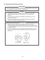
E. Removal and Replacement of Expansion Valve
IMPORTANT
Sometimes moisture in the refrigerant circuit exceeds the drier capacity and
freezes up at the expansion valve. Always install a new drier every time the
sealed refrigeration system is opened. Do not replace the drier until after all
other repair or replacement has been made.
1) Turn off the power supply.
2) Remove the panels.
3) Recover the refrigerant and store it in an approved container.
4) Remove the insulation and the expansion valve bulb on the suction line.
5) Remove the expansion valve cover, and disconnect the expansion valve using brazing
equipment.
6) Braze the new expansion valve with nitrogen gas flowing at a pressure of 3 to 4 PSIG.
WARNING
1. Do not heat the wall. Place a steel barrier for protection.
2. Always protect the valve body by using a damp cloth to prevent the valve
from overheating. Do not braze with the valve body exceeding 250°F.
7) Install the new drier.
8) Check for leaks using nitrogen gas (140 PSIG) and soap bubbles.
9) Evacuate the system, and charge it with refrigerant. See the nameplate for the required
refrigerant charge.
10) Attach the bulb to the suction line in position. Be sure to secure it with clamps and to
insulate it.
11) Place the new set of expansion valve covers in position.
12) Replace the panels in their correct position.
13) Turn on the power supply.
51
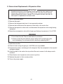
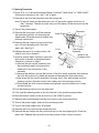
F. Removal and Replacement of Hot Gas Valve, Line Valve and Gas Valve
CAUTION
Always use a copper tube of the same diameter and length when replacing the
hot gas lines; otherwise the performance may be reduced.
IMPORTANT
Always install a new drier every time the sealed refrigeration system is opened.
Do not replace the drier until after all other repair or replacement has been
made.
1) Turn off the power supply.
2) Remove the panels.
3) Recover the refrigerant and store it in an approved container.
4) Remove the screw and the solenoid.
5) Disconnect the hot gas valve, line valve or gas valve using brazing equipment.
6) Install the new valve.
WARNING
Always protect the valve body by using a damp cloth to prevent the valve from
overheating. Do not braze with the valve body exceeding 250°F.
7) Install the new drier.
8) Check for leaks using nitrogen gas (140 PSIG) and soap bubbles.
9) Evacuate the system, and charge it with refrigerant. See the nameplate for the required
refrigerant charge.
10) Cut the leads of the solenoid allowing enough lead length to reconnect using closed
end connectors.
11) Connect the new solenoid leads.
12) Attach the solenoid to the valve body, and secure it with a screw.
13) Replace the panels in their correct positions.
14) Turn on the power supply.
52
G. Removal and Replacement of Evaporator
IMPORTANT
Always install a new drier every time the sealed refrigeration system is opened.
Do not replace the drier until after all other repairs or replacement have been
made.
1) Turn off the power supply.
2) Remove the panels and the top insulation over the evaporator.
3) Recover the refrigerant and store it in an approved container.
4) Remove the spray tubes and the insulations at the "U" shaped notch where the
refrigeration tubings go through the molded chassis.
5) Remove the insulation tube, and disconnect the evaporator inlet tubing at the tee next
to the expansion valve.
6) Lift up the evaporator, and disconnect the evaporator outlet tubing.
7) Install the new evaporator.
8) Install the new drier.
9) Check for leaks using nitrogen gas (140 PSIG) and soap bubbles.
10) Evacuate the system, and charge it with refrigerant. See the nameplate for the required
refrigerant charge.
11) Replace the removed parts in the reverse order of which they were removed.
12) Replace the top insulation and the panels in their correct positions.
13) Turn on the power supply.
H. Removal and Replacement of Thermistor
CAUTION
1. Fragile, handle very carefully.
2. Always use a recommended sealant (high thermal conductive type), Model
KE4560RTV manufactured by SHINETSU SILICONE, Part Code 60Y00011, or Part Code 4A0683-01 equivalent.
3. Always use a recommended foam insulation (non-absorbent type) or
equivalent.
1) Turn off the power supply.
2) Remove the panels.
3) Remove the control box cover.
4) Disconnect the thermistor leads from the K3 connector on the controller board.
53
5) Remove the plastic cable ties, foam
insulation, thermistor holder, and
thermistor. See Fig. 1.
Thermistor Lead
Cable Tie
6) Scrape away the old sealant on the
thermistor holder and the suction pipe.
7) Wipe off moisture or condensation on the
suction pipe.
8) Smoothly apply recommended sealant
(KE4560RTV, Part Code 60Y000-11
or 4A0683-01) to the thermistor holder
concave.
Foam Insulation
Thermistor Holder
Fig. 1
9) Attach the new thermistor to the suction pipe very carefully to prevent damage to the
leads. And secure it using the thermistor holder and recommended foam insulation.
10) Secure the insulation using the plastic cable ties.
11) Connect the thermistor leads through the bushing of the control box to the K3 connector
on the controller board.
Note: Do not cut the leads of the thermistor while installing it.
12) Replace the control box cover and the panels in their correct positions.
13) Turn on the power supply.
I. Removal and Replacement of Fan Motor
Note: When replacing a fan motor with defective winding, it is recommended that a new
capacitor be installed.
1) Turn off the power supply.
2) Remove the panels.
3) Remove the connectors from the fan motor leads.
4) Remove the fan motor bracket and fan motor.
5) Install the new fan motor, and replace the removed parts in the reverse order of which
they were removed.
6) Replace the panels in their correct positions.
7) Turn on the power supply.
J. Removal and Replacement of Water Valve
1) Turn off the power supply.
2) Close the water supply line shut-off valve.
3) Remove the front panel.
4) Remove the valve outlet tubing by releasing the clamp.
5) Remove the bracket from the unit.
6) Remove the fitting nut and water valve.
54
7) Disconnect the terminals from the water valve.
8) Install the new water valve, and replace the removed parts in the reverse order of which
they were removed.
9) Open the water supply line shut-off valve.
10) Turn on the power supply.
11) Check for leaks.
12) Replace the front panel in its correct position.
K. Removal and Replacement of Pump Motor
1) Turn off the power supply.
Separator
Cube Guide
2) Remove the front panel.
3) Drain the water tank by removing the
insulation panel and the cap at the front of
the ice dropping hole. See Fig. 2.
4) Replace the removed parts in their correct
positions. Be careful not to cross thread the
cap.
Front
Float Switch
Assembly
Inside of Ice
Dropping Hole
5) Disconnect the pump suction and discharge
hoses.
6) Remove the screws and the pump motor
bracket.
7) Remove the closed end connectors from the
pump motor leads.
Cap
Fig. 2
8) Remove the two screws and the pump motor bracket.
9) Remove the pump housing, and check the impeller.
10) If the impeller is defective, install a new impeller.
11) Install the new motor or new parts, and replace the removed parts in the reverse order
of which they were removed.
12) Turn on the power supply, and check for leaks.
13) Replace the front panel in its correct position.
L. Removal and Replacement of Spray Tubes
1) Turn off the power supply.
2) Remove the front panel and the insulation panel.
3) Remove the rubber hoses from the spray tubes (water supply pipe).
4) Release the clamps, and disconnect the rubber hoses.
5) Remove the spray tubes by squeezing the side tabs.
6) Install the new spray tubes, and replace the removed parts in the reverse order of which
they were removed.
7) Replace the panels in their correct positions.
8) Turn on the power supply.
55
M. Removal and Replacement of Water Regulating Valve –
Water-Cooled Model Only
IMPORTANT
Always install a new drier every time the sealed refrigeration system is opened.
Do not replace the drier until after all other repair or replacement has been
made.
1) Turn off the power supply.
2) Close the water supply line shut-off valve.
3) Remove the panels.
4) Recover the refrigerant and store it in an approved container.
5) Disconnect the capillary tube at the condenser outlet using brazing equipment.
6) Disconnect the flare-connections of the valve.
7) Remove the screws and the valve from the bracket.
8) Install the new valve, and braze the capillary tube.
9) Install the new drier.
10) Check for leaks using nitrogen gas (140 PSIG) and soap bubbles.
11) Evacuate the system, and charge it with refrigerant. See the nameplate for the
required refrigerant charge.
12) Connect the flare-connections.
13) Open the water supply line shut-off valve.
14) Check for water leaks.
15) Replace the panels in their correct positions.
56
N. Adjustment Of Water Regulating Valve – Water-Cooled Model Only
The water regulating valve (also called "water regulator") is factory-adjusted. No
adjustment is required under normal use. Adjust the water regulator, if necessary, using
the following procedure.
1) Attach a pressure gauge to the high-side line of the system. Or prepare a thermometer
to check for the condenser drain temperature.
2) Rotate the adjustment screw by using a flat blade screwdriver, so that the pressure
gauge shows 270 PSIG or the thermometer reads 104 to 115°F, 5 minutes after a
freeze cycle or icemaking process starts. When the pressure exceeds 270 PSIG,
or the condenser drain temperature exceeds 115°F, rotate the adjustment screw
counterclockwise. See Fig. 3.
3) Check that the pressure or the condenser drain temperature holds a stable setting.
Adjustment Screw
Adjustment Screw
CW – Higher
CCW – Lower
Top View
Fig. 3
57
O. Removal and Replacement of Condensing Pressure Regulator (C.P.R.)
– Remote Air-Cooled Model Only
IMPORTANT
Always install a new drier every time the sealed refrigeration system is opened.
Do not replace the drier until after all other repair or replacement has been
made.
1) Turn off the power supply.
2) Remove the panels from the remote condenser unit.
3) Recover the refrigerant and store it in an approved container.
4) Before heating, break off the stub on the dome to release the dome charge.
5) Disconnect the C.P.R. using brazing equipment.
6) Install the new C.P.R. Use nitrogen gas flowing at a pressure of 3 to 4 PSIG when
brazing the C.P.R.
WARNING
Always protect the C.P.R. body by using a damp cloth to prevent the C.P.R. from
overheating. Do not braze with the C.P.R. body exceeding 250°F.
7) Install a new drier in the icemaker.
8) Check for leaks using nitrogen gas (140 PSIG) and soap bubbles.
9) Evacuate the system and charge it with refrigerant. See the charge label in the machine
compartment in the icemaker.
10) Replace the panels in their correct positions.
11) Turn on the power supply.
58
VI. Cleaning and Maintenance
IMPORTANT
Ensure all components, fasteners and thumbscrews are securely in place after
any maintenance or cleaning is done to the equipment.
A. Preparing the Icemaker for Long Storage
WARNING
When shutting off the icemaker for an extended time, drain out all water from
the water tank and remove the ice from the storage bin. The storage bin should
be cleaned and dried. Drain the icemaker to prevent damage to the water
supply line at sub-freezing temperatures, using air or carbon dioxide. Shut off
the icemaker until the proper ambient temperature is resumed.
When the icemaker is not used for two or three days, it is sufficient to only move
the control switch to the "OFF" position, unless the icemaker will be at sub-freezing
temperatures.
1. Remove the water from the potable water supply line:
1) Remove the front panel. (Except water-cooled model)
2) Move the control switch on the control box to the "OFF" position.
3) Wait 3 minutes.
4) Close the potable water supply line shut-off valve and open the potable water supply line
drain valve.
5) Allow the line to drain by gravity.
6) Attach compressed air or carbon dioxide supply to the potable water line drain valve.
7) Move the control switch to the "ICE" position.
8) Blow the potable water line out using compressed air or carbon dioxide.
Separator
Cube Guide
2. Drain the potable water tank:
1) Turn off the power supply.
2) Move the control switch to the "OFF" position.
3) Drain the water tank by removing the
insulation panel and the cap located on the
front bottom part of the ice dropping hole.
See Fig. 4.
Front
Float Switch
Assembly
4) Replace the removed parts in their correct
positions. Be careful not to cross thread the
cap.
5) Remove all ice from the storage bin, and
clean the storage bin.
6) Replace the front panel in its correct position.
7) Close the drain valve.
59
Inside of Ice
Dropping Hole
Cap
Fig. 4
B. Cleaning and Sanitizing Instructions
IMPORTANT
Ensure all components, fasteners and thumbscrews are securely in place after
any maintenance or cleaning is done to the equipment.
WARNING
1. HOSHIZAKI recommends cleaning this unit at least once a year. More
frequent cleaning, however, may be required in some existing water
conditions.
2. To prevent injury to individuals and damage to the icemaker, do not use
ammonia type cleaners.
3. Always wear liquid-proof gloves to prevent the cleaning and sanitizing
solutions from coming into contact with skin.
IMPORTANT
1. The cleaning valve is used to allow solution flow to the inside of the
evaporator during the cleaning and sanitizing operation. It should be closed
for all icemaking operation. The compressor will not operate unless this valve
is completely closed.
2. To open the cleaning valve, the valve handle should be parallel to the valve
body. To close the valve, the valve handle should be at a right angle to the
valve body.
Closed Position
Open Position
60
1. Cleaning Procedure
1) Dilute 38 fl. oz. of the recommended cleaner Hoshizaki "Scale Away" or "LIME-A-WAY"
(Economics Laboratory, Inc.) with 7 gal. of water.
2) Remove all ice from the evaporator and the storage bin.
Note: To remove cubes on the evaporator, turn off the power supply and turn it on
after 3 minutes. The defrost cycle starts and the cubes will be removed from the
evaporator.
3) Turn off the power supply.
4) Remove the front panel, and then remove
the insulation panel by first removing the
thumbscrew, lifting the panel up slightly and
pulling it towards you.
5) Remove the cap located on the front bottom
part of the ice dropping hole. Drain the
water tank. See Fig. 5.
6) Replace the cap in its correct position. Be
careful not to cross thread it.
Cube Guide
Front
Separator
Float Switch
Assembly
Inside of Ice
7) In bad or severe water conditions, clean the
Dropping Hole
float switch assembly as described below.
Otherwise, continue to step 8.
a. Remove the float switch assembly from
Cap
the mounting bracket and remove the
Fig. 5
rubber boot from the bottom of the
assembly.
b. Remove the retainer rod from the bottom of the float switch assembly, then remove
the float. Be careful not to bend the retainer rod excessively when removing it.
c. Wipe down the float switch assembly's housing, shaft, float, and retainer rod with
cleaning solution. Wipe the inside of the rubber boot with cleaning solution.
d. Reassemble the float switch assembly and replace it and the rubber boot in their
correct positions.
8) Pour the cleaning solution into the water tank.
9) Fully open the cleaning valve on the left side wall of the machine compartment.
10) Move the control switch on the control box to the "WASH" position.
11) Replace the insulation panel and the front panel in their correct positions.
12) Turn on the power supply, and start the washing process.
13) Turn off the power supply after 30 minutes.
14) Remove the front panel and the insulation panel.
15) Remove the cap located on the front bottom part of the ice dropping hole. Drain the
water tank. Replace the cap and the insulation panel in their correct positions.
61
16) Move the control switch to the "ICE" position.
17) Close the cleaning valve.
Note: The icemaker will not operate unless the cleaning valve is completely closed.
18) Replace the front panel in its correct position.
19) Turn on the power supply to fill the water tank with water.
20) Turn off the power supply after 3 minutes.
21) Remove the front panel, and fully open the cleaning valve.
22) Move the control switch to the "WASH" position.
23) Replace the front panel in its correct position.
24) Turn on the power supply to rinse off the cleaning solution.
25) Turn off the power supply after 5 minutes.
26) Remove the front panel and the insulation panel.
27) Remove the cap located on the front bottom part of the ice dropping hole. Drain the
water tank. Replace the cap and the insulation panel in their correct positions.
Note: Do not replace the insulation panel when you proceed to "Sanitizing Procedure."
28) Repeat the above steps 16 through 27 three more times to rinse thoroughly.
Note: If you do not sanitize the icemaker, go to step 9 in "Sanitizing Procedure."
2. Sanitizing Procedure - Following Cleaning Procedure
1) Dilute a 5.25% sodium hypochlorite solution (chlorine bleach) with water (add 3.5 fl. oz.
of sanitizer to 7 gal. of water).
2) Pour the sanitizing solution into the water tank.
3) Replace the insulation panel and the front panel in their correct positions.
Note: Make sure that the control switch is in the "WASH" position and the cleaning
valve is open.
4) Turn on the power supply, and start the sanitizing process.
5) Turn off the power supply after 15 minutes.
6) Remove the front panel and the insulation panel.
7) Remove the cap located on the front bottom part of the ice dropping hole. Drain the
water tank. Replace the cap and the insulation panel in their correct positions.
8) Repeat the above steps 16 through 27 in "Cleaning Procedure" two times to rinse
thoroughly.
9) Close the cleaning valve.
10) Move the control switch to the "ICE" position.
11) Replace the front panel in its correct position.
12) Clean the storage bin with water.
13) Turn on the power supply, and start the automatic icemaking process.
62
C. Maintenance
IMPORTANT
This icemaker must be maintained individually, referring to the instruction
manual and labels provided with the icemaker.
1. Stainless Steel Exterior
To prevent corrosion, wipe the exterior occasionally with a clean and soft cloth. Use a
damp cloth containing a neutral cleaner to wipe off oil or dirt build up.
2. Storage Bin and Scoop
• Wash your hands before removing ice. Use the plastic scoop provided.
• The storage bin is for ice use only. Do not store anything else in the bin.
• Keep the scoop clean. Clean it by using a neutral cleaner and rinse thoroughly.
• Clean the bin liner by using a neutral cleaner. Rinse thoroughly after cleaning.
3. Air Filters
Plastic mesh air filters remove dirt or dust from the air, and keep the condenser from
getting clogged. As the filters get clogged, the icemaker’s performance will be reduced.
Check the filters at least twice a month. When clogged, use warm water and a neutral
cleaner to wash the filters.
4. Condenser
Check the condenser once a year, and clean if required by using a brush or vacuum
cleaner. More frequent cleaning may be required depending on the location of the
icemaker.
63