1
TM-229 409A
2006−12
Eff w/Serial Number LG250111A
Processes
Multiprocess Welding
Description
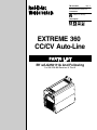
Arc Welding Power Source
EXTREME 360
CC/CV Auto-Line
File: MULTIPROCESS
TABLE OF CONTENTS
SECTION 1 − SAFETY PRECAUTIONS FOR SERVICING . . . . . . . . . . . . . . . . . . . . . . . . . . . . . . . . . . . . . . . . . .
1-1. Symbol Usage . . . . . . . . . . . . . . . . . . . . . . . . . . . . . . . . . . . . . . . . . . . . . . . . . . . . . . . . . . . . . . . . . . . . . . . .
1-2. Servicing Hazards . . . . . . . . . . . . . . . . . . . . . . . . . . . . . . . . . . . . . . . . . . . . . . . . . . . . . . . . . . . . . . . . . . . .
1-3. California Proposition 65 Warnings . . . . . . . . . . . . . . . . . . . . . . . . . . . . . . . . . . . . . . . . . . . . . . . . . . . . . . .
1-4. EMF Information . . . . . . . . . . . . . . . . . . . . . . . . . . . . . . . . . . . . . . . . . . . . . . . . . . . . . . . . . . . . . . . . . . . . . .
SECTION 2 − INTRODUCTION . . . . . . . . . . . . . . . . . . . . . . . . . . . . . . . . . . . . . . . . . . . . . . . . . . . . . . . . . . . . . . . . .
2-1. Specifications . . . . . . . . . . . . . . . . . . . . . . . . . . . . . . . . . . . . . . . . . . . . . . . . . . . . . . . . . . . . . . . . . . . . . . . .
2-2. Volt-Ampere Curves . . . . . . . . . . . . . . . . . . . . . . . . . . . . . . . . . . . . . . . . . . . . . . . . . . . . . . . . . . . . . . . . . . .
2-3. Duty Cycle And Overheating . . . . . . . . . . . . . . . . . . . . . . . . . . . . . . . . . . . . . . . . . . . . . . . . . . . . . . . . . . . .
SECTION 3 − INSTALLATION . . . . . . . . . . . . . . . . . . . . . . . . . . . . . . . . . . . . . . . . . . . . . . . . . . . . . . . . . . . . . . . . . .
3-1. Selecting a Location . . . . . . . . . . . . . . . . . . . . . . . . . . . . . . . . . . . . . . . . . . . . . . . . . . . . . . . . . . . . . . . . . . .
3-2. Connecting 1-Phase Input Power . . . . . . . . . . . . . . . . . . . . . . . . . . . . . . . . . . . . . . . . . . . . . . . . . . . . . . . .
3-3. Connecting 3-Phase Input Power . . . . . . . . . . . . . . . . . . . . . . . . . . . . . . . . . . . . . . . . . . . . . . . . . . . . . . . .
3-4. Electrical Service Guide . . . . . . . . . . . . . . . . . . . . . . . . . . . . . . . . . . . . . . . . . . . . . . . . . . . . . . . . . . . . . . . .
3-5. Weld Output Receptacles And Selecting Cable Sizes . . . . . . . . . . . . . . . . . . . . . . . . . . . . . . . . . . . . . . .
3-6. Remote 14 Receptacle Information . . . . . . . . . . . . . . . . . . . . . . . . . . . . . . . . . . . . . . . . . . . . . . . . . . . . . . .
3-7. Optional Gas Valve Operation And Shielding Gas Connection . . . . . . . . . . . . . . . . . . . . . . . . . . . . . . . .
SECTION 4 − OPERATION . . . . . . . . . . . . . . . . . . . . . . . . . . . . . . . . . . . . . . . . . . . . . . . . . . . . . . . . . . . . . . . . . . . .
4-1. Front Panel Controls . . . . . . . . . . . . . . . . . . . . . . . . . . . . . . . . . . . . . . . . . . . . . . . . . . . . . . . . . . . . . . . . . . .
4-2. Meter Functions . . . . . . . . . . . . . . . . . . . . . . . . . . . . . . . . . . . . . . . . . . . . . . . . . . . . . . . . . . . . . . . . . . . . . .
4-3. Mode Switch Settings . . . . . . . . . . . . . . . . . . . . . . . . . . . . . . . . . . . . . . . . . . . . . . . . . . . . . . . . . . . . . . . . . .
4-4. Lift-Arc TIG Procedure . . . . . . . . . . . . . . . . . . . . . . . . . . . . . . . . . . . . . . . . . . . . . . . . . . . . . . . . . . . . . . . . .
4-5. Stick Start Procedure . . . . . . . . . . . . . . . . . . . . . . . . . . . . . . . . . . . . . . . . . . . . . . . . . . . . . . . . . . . . . . . . . .
SECTION 5 − THEORY OF OPERATION . . . . . . . . . . . . . . . . . . . . . . . . . . . . . . . . . . . . . . . . . . . . . . . . . . . . . . . .
SECTION 6 − TROUBLESHOOTING . . . . . . . . . . . . . . . . . . . . . . . . . . . . . . . . . . . . . . . . . . . . . . . . . . . . . . . . . . . .
6-1. Checking Unit Before Applying Power . . . . . . . . . . . . . . . . . . . . . . . . . . . . . . . . . . . . . . . . . . . . . . . . . . . .
6-2. Pre-Power Flowchart . . . . . . . . . . . . . . . . . . . . . . . . . . . . . . . . . . . . . . . . . . . . . . . . . . . . . . . . . . . . . . . . . .
6-3. Measuring Input Capacitor Voltage . . . . . . . . . . . . . . . . . . . . . . . . . . . . . . . . . . . . . . . . . . . . . . . . . . . . . . .
6-4. Input Pre-Regulator Module (MOD1) . . . . . . . . . . . . . . . . . . . . . . . . . . . . . . . . . . . . . . . . . . . . . . . . . . . . .
6-5. Input Pre-Regulator Module (MOD1) Test Point Values . . . . . . . . . . . . . . . . . . . . . . . . . . . . . . . . . . . . . .
6-6. Inverter Module (MOD2) . . . . . . . . . . . . . . . . . . . . . . . . . . . . . . . . . . . . . . . . . . . . . . . . . . . . . . . . . . . . . . .
6-7. Inverter Module (MOD2) Test Point Values . . . . . . . . . . . . . . . . . . . . . . . . . . . . . . . . . . . . . . . . . . . . . . . .
6-8. Power Switch (S1) . . . . . . . . . . . . . . . . . . . . . . . . . . . . . . . . . . . . . . . . . . . . . . . . . . . . . . . . . . . . . . . . . . . .
6-9. Output Diodes D1, D2 . . . . . . . . . . . . . . . . . . . . . . . . . . . . . . . . . . . . . . . . . . . . . . . . . . . . . . . . . . . . . . . . .
6-10. Output Diodes D1, D2 Test Point Values . . . . . . . . . . . . . . . . . . . . . . . . . . . . . . . . . . . . . . . . . . . . . . . . . .
6-11. Stick Boost Rectifier (SR1) . . . . . . . . . . . . . . . . . . . . . . . . . . . . . . . . . . . . . . . . . . . . . . . . . . . . . . . . . . . . .
6-12. Stick Boost Rectifier (SR1) Test Point Values . . . . . . . . . . . . . . . . . . . . . . . . . . . . . . . . . . . . . . . . . . . . . .
6-13. Control/Auxiliary Power Board PC1 − Auxiliary Power Circuit . . . . . . . . . . . . . . . . . . . . . . . . . . . . . . . . .
6-14. Control/Auxiliary Power Board PC1 − Auxiliary Power Circuit Test Point Values . . . . . . . . . . . . . . . . . .
6-15. Control/Auxiliary Power Board PC1 − Pre-Regulator Control Circuit . . . . . . . . . . . . . . . . . . . . . . . . . . .
6-16. Control/Auxiliary Power Board PC1 − Pre-Regulator Control Circuit Test Point Values . . . . . . . . . . . .
6-17. Control/Auxiliary Power Board PC1 − Inverter Control Circuit . . . . . . . . . . . . . . . . . . . . . . . . . . . . . . . . .
6-18. Control/Auxiliary Power Board PC1 − Inverter Control Circuit Test Point Values . . . . . . . . . . . . . . . . . .
6-19. Power Interconnect Board (PC2) . . . . . . . . . . . . . . . . . . . . . . . . . . . . . . . . . . . . . . . . . . . . . . . . . . . . . . . .
6-20. Power Interconnect Board (PC2) Test Point Values . . . . . . . . . . . . . . . . . . . . . . . . . . . . . . . . . . . . . . . . .
6-21. Troubleshooting Table . . . . . . . . . . . . . . . . . . . . . . . . . . . . . . . . . . . . . . . . . . . . . . . . . . . . . . . . . . . . . . . . .
6-22. Voltmeter/Ammeter Diagnostics . . . . . . . . . . . . . . . . . . . . . . . . . . . . . . . . . . . . . . . . . . . . . . . . . . . . . . . . .
6-23. Enabling Low Open Circuit Voltage Stick Mode (Optional) . . . . . . . . . . . . . . . . . . . . . . . . . . . . . . . . . . . .
6-24. Troubleshooting Circuit Diagram . . . . . . . . . . . . . . . . . . . . . . . . . . . . . . . . . . . . . . . . . . . . . . . . . . . . . . . . .
6-25. Control/Auxiliary Power Board PC1 Testing Information (Use with Section 6-26) . . . . . . . . . . . . . . . . .
6-26. Control/Auxiliary Power Board PC1 Test Point Values . . . . . . . . . . . . . . . . . . . . . . . . . . . . . . . . . . . . . . .
1
1
1
2
2
3
3
3
4
5
5
6
7
8
9
9
10
11
11
12
12
13
13
14
17
17
18
19
20
20
21
21
22
23
23
24
24
26
27
28
29
30
31
32
33
34
36
37
38
40
41
TABLE OF CONTENTS
6-27. Power Interconnect Board PC2 Testing Information (Use with Section 6-28) . . . . . . . . . . . . . . . . . . . .
6-28. Power Interconnect Board PC2 Test Point Values . . . . . . . . . . . . . . . . . . . . . . . . . . . . . . . . . . . . . . . . . .
6-29. Front Panel/Display Board PC3 Testing Information (Use with Section 6-30) . . . . . . . . . . . . . . . . . . . .
6-30. Front Panel/Display Board PC3 Test Point Values . . . . . . . . . . . . . . . . . . . . . . . . . . . . . . . . . . . . . . . . . .
6-31. Checking Unit Output After Servicing . . . . . . . . . . . . . . . . . . . . . . . . . . . . . . . . . . . . . . . . . . . . . . . . . . . . .
SECTION 7 − MAINTENANCE . . . . . . . . . . . . . . . . . . . . . . . . . . . . . . . . . . . . . . . . . . . . . . . . . . . . . . . . . . . . . . . . .
7-1. Routine Maintenance . . . . . . . . . . . . . . . . . . . . . . . . . . . . . . . . . . . . . . . . . . . . . . . . . . . . . . . . . . . . . . . . . .
7-2. Blowing Out Inside Of Unit . . . . . . . . . . . . . . . . . . . . . . . . . . . . . . . . . . . . . . . . . . . . . . . . . . . . . . . . . . . . . .
SECTION 8 − ELECTRICAL DIAGRAMS . . . . . . . . . . . . . . . . . . . . . . . . . . . . . . . . . . . . . . . . . . . . . . . . . . . . . . . .
SECTION 9 − PARTS LIST FOR LG250111A AND FOLLOWING . . . . . . . . . . . . . . . . . . . . . . . . . . . . . . . . . . . .
44
45
47
48
49
50
50
50
51
60
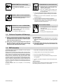
SECTION 1 − SAFETY PRECAUTIONS FOR SERVICING
1-1. Symbol Usage
OM-229 409-B, safety_stm 8/03
Means Warning! Watch Out! There are possible hazards
with this procedure! The possible hazards are shown in
the adjoining symbols.
Y Marks a special safety message.
. Means “Note”; not safety related.
This group of symbols means Warning! Watch Out! possible
ELECTRIC SHOCK, MOVING PARTS, and HOT PARTS hazards.
Consult symbols and related instructions below for necessary actions
to avoid the hazards.
1-2. Servicing Hazards
Y The symbols shown below are used throughout this manual to
call attention to and identify possible hazards. When you see
the symbol, watch out, and follow the related instructions to
avoid the hazard.
Y Only qualified persons should service, test, maintain, and repair this unit.
Y During servicing, keep everybody, especially children, away.
ELECTRIC SHOCK can kill.
D Do not touch live electrical parts.
D Turn Off welding power source and wire feeder
and disconnect and lockout input power using
line disconnect switch, circuit breakers, or by removing plug from receptacle, or stop engine before servicing unless the procedure specifically requires an energized unit.
D
Insulate yourself from ground by standing or working on dry insulating mats big enough to prevent contact with the ground.
D
Do not leave live unit unattended.
D
If this procedure requires an energized unit, have only personnel
familiar with and following standard safety practices do the job.
D
When testing a live unit, use the one-hand method. Do not put both
hands inside unit. Keep one hand free.
D
Disconnect input power conductors from deenergized supply line
BEFORE moving a welding power source.
SIGNIFICANT DC VOLTAGE exists after removal of
input power on inverters.
D
Turn Off inverter, disconnect input power, and discharge input
capacitors according to instructions in Maintenance Section before
touching any parts.
STATIC (ESD) can damage PC boards.
D Put on grounded wrist strap BEFORE handling
boards or parts.
D Use proper static-proof bags and boxes to
store, move, or ship PC boards.
FIRE OR EXPLOSION hazard.
D Do not place unit on, over, or near combustible
surfaces.
D Do not service unit near flammables.
Extreme 360
FLYING METAL can injure eyes.
D Wear safety glasses with side shields or face
shield during servicing.
D Be careful not to short metal tools, parts, or
wires together during testing and servicing.
HOT PARTS can cause severe burns.
D Do not touch hot parts bare handed.
D Allow cooling period before working on welding
gun or torch.
EXPLODING PARTS can cause injury.
D Failed parts can explode or cause other parts to
explode when power is applied to inverters.
D Always wear a face shield and long sleeves
when servicing inverters.
SHOCK HAZARD from testing.
D Turn Off welding power source and wire feeder
or stop engine before making or changing meter lead connections.
D Use at least one meter lead that has a selfretaining spring clip such as an alligator clip.
D Read instructions for test equipment.
FALLING UNIT can cause injury.
D Use lifting eye to lift unit only, NOT running
gear, gas cylinders, or any other accessories.
D Use equipment of adequate capacity to lift and
support unit.
D If using lift forks to move unit, be sure forks are
long enough to extend beyond opposite side of
unit.
MOVING PARTS can cause injury.
D Keep away from moving parts such as fans.
D Keep all doors, panels, covers, and guards
closed and securely in place.
TM-229 409 Page 1
MOVING PARTS can cause injury.
D Keep away from moving parts.
D Keep away from pinch points such as drive
rolls.
MAGNETIC FIELDS can affect pacemakers.
D Pacemaker wearers keep away from servicing
areas until consulting your doctor.
OVERUSE can cause OVERHEATING.
D Allow cooling period; follow rated duty cycle.
D Reduce current or reduce duty cycle before
starting to weld again.
D Do not block or filter airflow to unit.
H.F. RADIATION can cause interference.
D High-frequency (H.F.) can interfere with radio
navigation, safety services, computers, and
communications equipment.
D Have only qualified persons familiar with
electronic equipment install, test, and service
H.F. producing units.
D The user is responsible for having a qualified electrician promptly correct any interference problem resulting from the installation.
D If notified by the FCC about interference, stop using the
equipment at once.
D Have the installation regularly checked and maintained.
D Keep high-frequency source doors and panels tightly shut, keep
spark gaps at correct setting, and use grounding and shielding to
minimize the possibility of interference.
READ INSTRUCTIONS.
D Use Testing Booklet (Part No. 150 853) when
servicing this unit.
D Consult the Owner’s Manual for welding safety
precautions.
D Use only genuine replacement parts.
1-3. California Proposition 65 Warnings
Y Welding or cutting equipment produces fumes or gases which
contain chemicals known to the State of California to cause
birth defects and, in some cases, cancer. (California Health &
Safety Code Section 25249.5 et seq.)
For Gasoline Engines:
Y Engine exhaust contains chemicals known to the State of
California to cause cancer, birth defects, or other reproductive
harm.
Y Battery posts, terminals and related accessories contain lead
and lead compounds, chemicals known to the State of
California to cause cancer and birth defects or other
reproductive harm. Wash hands after handling.
For Diesel Engines:
Y Diesel engine exhaust and some of its constituents are known
to the State of California to cause cancer, birth defects, and
other reproductive harm.
1-4. EMF Information
Considerations About Welding And The Effects Of Low Frequency
Electric And Magnetic Fields
Welding current, as it flows through welding cables, will cause electromagnetic fields. There has been and still is some concern about such
fields. However, after examining more than 500 studies spanning 17
years of research, a special blue ribbon committee of the National
Research Council concluded that: “The body of evidence, in the
committee’s judgment, has not demonstrated that exposure to powerfrequency electric and magnetic fields is a human-health hazard.”
However, studies are still going forth and evidence continues to be
examined. Until the final conclusions of the research are reached, you
may wish to minimize your exposure to electromagnetic fields when
welding or cutting.
To reduce magnetic fields in the workplace, use the following
procedures:
TM-229 409 Page 2
1. Keep cables close together by twisting or taping them.
2. Arrange cables to one side and away from the operator.
3. Do not coil or drape cables around your body.
4. Keep welding power source and cables as far away from operator as practical.
5. Connect work clamp to workpiece as close to the weld as possible.
About Pacemakers:
Pacemaker wearers consult your doctor first. If cleared by your doctor,
then following the above procedures is recommended.
Extreme 360
SECTION 2 − INTRODUCTION
2-1. Specifications
Input
Power
Rated Output
3-Phase
350 A at 34
VDC, 60%
Duty Cycle
1-Phase
300 A at 32
VDC, 60%
Duty Cycle*
Voltage
Range in CV Mode
Amperage
Range in
CC Mode
Max.
OpenCircuit
Voltage
10−38 V
5−425 A
75 VDC
RMS Amps Input at Rated Load Output,
60 Hz 3-Phase at NEMA Load Voltages
and Class I Rating
208 V
230 V
400 V
460 V
575 V
KVA
KW
40.4
36.1
20.6
17.8
14.1
14.2
13.6
60.8
54.6
29.7
25.4
19.9
11.7
11.2
*See Section 2-3 for Duty Cycle Rating.
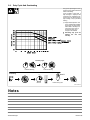
2-2. Volt-Ampere Curves
Volt-ampere curves show minimum
and maximum voltage and amperage output capabilities of welding
power source. Curves of other settings fall between curves shown.
A. CC Mode
100
90
80
VOLTS
70
60
50
SMAW
MAX
40
30
GTAW
MN
20
GTAW
MAX
SMAW
80A
0%
25%
10
ARC
CONTROL
50%
75%
100%
0
0
100
200
300
400
500
400
5 00
AMPERAGE
B. CV Mode
100
90
80
VOLTS
70
60
50
MAX
40
30
20
MIN
10
0
0
100
200
300
AMPERAGE
Extreme 360
217 836-A / 217 837-B
TM-229 409 Page 3
2-3. Duty Cycle And Overheating
Duty Cycle is percentage of 10 minutes that unit can weld at rated load
without overheating.
If unit overheats, output stops, a
Help message is displayed and
cooling fan runs. Wait fifteen minutes for unit to cool. Reduce amperage or voltage, or duty cycle before
welding.
. Single Phase Operation: The
unit is supplied with a 8 AWG
power cord. The rated output
with 8 AWG is 300 amps, 32
volts at 40% duty cycle. To
achieve 60% duty cycle
change cord to 6 AWG.
Y Exceeding duty cycle can
damage unit and void
warranty.
60% Duty Cycle
6 Minutes Welding
Overheating
4 Minutes Resting
A or V
0
15
Minutes
OR
Reduce Duty Cycle
Ref. 216 568-A
Notes
TM-229 409 Page 4
Extreme 360
SECTION 3 − INSTALLATION
3-1. Selecting a Location
24 in
(610 mm)
Dimensions And Weight
80 lb (36.3 kg)
17 in
(432 mm)
12-1/2 in
(318 mm)
1
Movement
1
Y Do not move or operate unit
where it could tip.
1
Lifting Handles
Use handles to lift unit.
2
Hand Cart
Use cart or similar device to move
unit.
3
Rating Information
Use rating information on rear panel
to determine input power needs.
4
Line Disconnect Device
Locate unit near correct input
power supply.
Y Special installation may be
required where gasoline or
volatile liquids are present −
see NEC Article 511 or CEC
Section 20.
2
Location
4
3
18 in
(460 mm)
18 in
(460 mm)
loc_2 3/96 - Ref. ST-151 556 / Ref. 803 691-C
Extreme 360
TM-229 409 Page 5
3-2. Connecting 1-Phase Input Power
Y Installation must meet all National and Local Codes − have
only qualified persons make
this installation.
Y Disconnect and lockout/tagout input power before connecting input conductors from
unit.
1
8
Y Always connect green or
green/yellow conductor to
supply grounding terminal
first, and never to a line terminal.
=GND/PE
Earth
Ground
. The Auto-Line circuitry in this unit
10
automatically adapts the power
source to the primary voltage being applied. Check input voltage
available at site. This unit can be
connected to any input power between 208 and 575 VAC without
removing cover to relink the power source.
7
9
L1
L2
1
2
3
1
3
4
5
1
6
2
3
6
5
4
Black And White Input
Conductor (L1 And L2)
Red Input Conductor
Green Or Green/Yellow
Grounding Conductor
Insulation Sleeving
Electrical Tape
Insulate and isolate red conductor as
shown.
6 Input Power Cord.
7 Disconnect Device (switch
shown in the OFF position)
8 Disconnect Device Grounding
Terminal
9 Disconnect Device Line
Terminals
Connect green or green/yellow
grounding conductor to disconnect
device grounding terminal first.
Connect input conductors L1 and L2
to disconnect device line terminals.
10 Overcurrent Protection
Select type and size of overcurrent
protection using Section 3-4 (fused
disconnect switch shown).
Close and secure door on disconnect
device. Remove lockout/tagout device, and place switch in the On position.
Tools Needed:
804 531-A
TM-229 409 Page 6
Extreme 360
3-3. Connecting 3-Phase Input Power
Y Installation must meet all National
and Local Codes − have only qualified persons make this installation.
Y Disconnect and lockout/tagout input power before connecting input
conductors from unit.
3
= GND/PE Earth Ground
4
Y Always connect green or green/
yellow conductor to supply
grounding terminal first, and never
to a line terminal.
. The Auto-Line circuitry in this unit au-
tomatically adapts the power source
to the primary voltage being applied.
Check input voltage available at site.
This unit can be connected to any input power between 208 and 575 VAC
without removing cover to relink the
power source.
7
For Three-Phase Operation
2
1
2
3
L1
3
L2
L3
6
4
5
5
6
Input Power Cord.
Disconnect Device (switch shown in
the OFF position)
Green Or Green/Yellow Grounding
Conductor
Disconnect Device Grounding
Terminal
Input Conductors (L1, L2 And L3)
Disconnect Device Line Terminals
Connect green or green/yellow grounding
conductor to disconnect device grounding
terminal first.
1
Connect input conductors L1, L2, and L3
to disconnect device line terminals.
7
Overcurrent Protection
Select type and size of overcurrent protection using Section 3-4 (fused disconnect
switch shown).
Close and secure door on disconnect
device. Remove lockout/tagout device,
and place switch in the On position.
Tools Needed:
804 531-A
Extreme 360
TM-229 409 Page 7
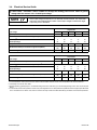
3-4. Electrical Service Guide
Y
CAUTION:
INCORRECT INPUT POWER can damage this welding power source. Phase to ground
voltage shall not exceed +10% of rated input voltage.
NOTE
Actual input voltage should not be 10% less than minimum and/or 10% more than
maximum input voltages listed in table. If actual input voltage is outside this range,
output may not be available.
Single-Phase
Input Voltage
208
230
400
460
575
Input Amperes At Rated Output
60.8
54.6
29.7
25.4
19.9
Time-Delay 2
70
60
35
30
25
Normal Operating 3
80
80
45
40
30
Min Input Conductor Size In AWG/Kcmil 4
8
8
10
12
12
72
(22)
89
(27)
176
(54)
140
(43)
219
(67)
8
8
10
12
12
Input Voltage
208
230
400
460
575
Input Amperes At Rated Output
40.4
36.1
20.6
17.8
14.1
Time-Delay 2
45
40
25
20
15
Normal Operating 3
60
50
30
25
20
Min Input Conductor Size In AWG/Kcmil 4
8
10
12
14
14
119
(36)
96
(29)
175
(53)
150
(46)
234
(71)
10
10
12
14
14
Max Recommended Standard Fuse Rating In Amperes 1
Max Recommended Input Conductor Length In Feet (Meters)
Min Grounding Conductor Size In AWG/Kcmil 4
Three-Phase
Max Recommended Standard Fuse Rating In Amperes 1
Max Recommended Input Conductor Length In Feet (Meters)
Min Grounding Conductor Size In AWG/Kcmil 4
1
2
3
4
Reference: 2005 National Electrical Code (NEC) (including article 630)
If a circuit breaker is used in place of af a fuse, choose a circuit breaker with time-current curves comparable to the recommended fuse.
“Time-Delay” fuses are UL class “RK5” .
“Normal Operating” (general purpose - no intentional delay) fuses are UL class “K5” (up to and including 60 amp), and UL class “H” (65 amp and
above).
Conductor data in this section specifies conductor size (excluding flexible cord or cable) between the panelboard and the equipment per NEC Table
310.16. If a flexible cord or cable is used, minimum conductor size may increase. See NEC Table 400.5(A) for flexible cord and cable requirements.
TM-229 409 Page 8
Extreme 360
3-5. Weld Output Receptacles And Selecting Cable Sizes
Total Cable (Copper) Length In Weld Circuit Not Exceeding
100 ft (30 m) Or Less
Weld Output
Terminals
+
−
Output Receptacles
150 ft
(45 m)
200 ft
(60 m)
250 ft
(70 m)
300 ft
(90 m)
350 ft
(105 m)
400 ft
(120 m)
Welding
Amperes
10 − 60%
Duty
Cycle
60 − 100%
Duty
Cycle
100
4
4
4
3
2
1
1/0
1/0
150
3
3
2
1
1/0
2/0
3/0
3/0
200
3
2
1
1/0
2/0
3/0
4/0
4/0
250
2
1
1/0
2/0
3/0
4/0
2-2/0
2-2/0
300
1
1/0
2/0
3/0
4/0
2-2/0
2-3/0
2-3/0
350
1/0
2/0
3/0
4/0
2-2/0
2-3/0
2-3/0
2-4/0
400
1/0
2/0
3/0
4/0
2-2/0
2-3/0
2-4/0
2-4/0
500
2/0
3/0
4/0
2-2/0
2-3/0
2-4/0
3-3/0
3-3/0
600
3/0
4/0
2-2/0
2-3/0
2-4/0
3-3/0
3-4/0
3-4/0
10 − 100% Duty Cycle
Weld cable size (AWG) is based on either a 4 volts or less drop or a current density of at least 300 circular mils per ampere.
S-0007-D
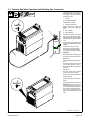
3-6. Remote 14 Receptacle Information
Socket*
24 VOLTS AC
A
B
K
J
A
24 volts ac. Protected by circuit breaker CB2.
B
Contact closure to A completes 24 volts ac
contactor control circuit.
I
115 volts ac. Protected by circuit breaker CB1.
J
Contact closure to I completes 115 volts ac
contactor control circuit.
C
Output to remote control; 0 to +10 volts dc, +10
volts dc in MIG mode.
D
Remote control circuit common.
E
0 to +10 volts dc input command signal from
remote control.
M
CC/CV select
F
Current feedback; +1 volt dc per 100 amperes.
H
Voltage feedback; +1 volt dc per 10 output receptacle volts.
G
Circuit common for 24 and 115 volts ac circuits.
K
Chassis common.
I
H
C L N
M
D
G
E F
115 VOLTS AC
REMOTE
OUTPUT
CONTROL
A/V
AMPERAGE
VOLTAGE
GND
Socket Information
*The remaining sockets are not used.
Extreme 360
TM-229 409 Page 9
‘
3-7. Optional Gas Valve Operation And Shielding Gas Connection
Obtain gas cylinder and chain to
running gear, wall, or other stationary support so cylinder cannot fall
and break off valve.
4
1
Cylinder
2
Regulator/Flowmeter
Install so face is vertical.
3
GAS IN
Gas Hose Connection
Fitting has 5/8-18 right-hand
threads. Obtain and install gas
hose.
2
4
Gas In Fitting
5
Gas Out Fitting
The Gas In and Gas Out fittings
have 5/8-18 right-hand threads.
Obtain proper size, type, and length
hose and make connections as follows:
Connect hose from shielding gas
supply regulator/flowmeter to Gas
In fitting.
Connect hose coupler to torch.
Connect one end of gas hose to
hose coupler. Connect remaining
end of gas hose to Gas Out fitting.
Operation
3
1
The gas solenoid controls gas flow
during the TIG process as follows:
Remote TIG
Gas flow starts with remote contactor on.
Gas flow stops at end of post−flow
if current was detected, or with remote contactor off if no current was
detected.
Lift−Arc TIG
Gas flow starts when tungsten
touches work (touch sensed).
Gas flow stops at end of post−flow.
Scratch Start TIG
5
GAS OUT
Gas flow starts when current is detected.
Gas flow stops at end of post−flow.
Post−flow time is factory set to 5
seconds per 100 amps of weld current. The minimum post−flow time
is 5 seconds. The maximum post−
flow is 20 seconds (post flow settings are not adjustable by the end
user).
Ref. 803 705-A / Ref. 803 691-C
TM-229 409 Page 10
Extreme 360
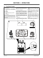
SECTION 4 − OPERATION
4-1. Front Panel Controls
1
Power Switch
. The
fan motor is thermostatically
controlled and only runs when cooling is
needed.
2 Voltmeter
3 Ammeter
4 V/A (Voltage/Amperage) Adjustment
Control
5 Mode Switch
The Mode switch setting determines both the
process and output On/Off control (see Section 4-3). Source of control (panel or remote)
for the amount of output is selected on the V/A
Control switch.
For Air Carbon Arc (CAC-A) cutting and goug-
ing, place switch in Stick position. For best results, place Arc Control in the maximum position.
6 Remote 14 Receptacle
For remote control, make connections to Remote 14 receptacle. In TIG modes and the
REMOTE STICK mode, remote control is a
percent of V/A Adjust control setting (value
selected on V/A Adjust is maximum available
on remote). In ELECTRODE HOT STICK
mode the remote control is not used. In the
MIG mode, remote control provides full range
of unit output regardless of V/A Adjust control
setting.
7 Arc Control
Control adjusts Dig when Stick or CC mode is
selected on mode switch. When set towards
2
3
minimum, short-circuit amperage at low arc
voltage is the same as normal welding
amperage.
When set towards maximum, short-circuit
amperage is increased at low arc voltage to
assist with arc starts as well as reduce sticking while welding.
Select setting best suited for application.
Control adjusts inductance when MIG or
V-Sense Feeder position is selected on the
mode switch. Inductance determines the
“wetness” of the weld puddle. When set towards maximum, “wetness” (puddle fluidity)
increases.
When Pulsed MIG or one of the TIG modes is
selected, this control is not functional.
4
V/A ADJUST
ELECTRODE HOT
REMOTE
ARC CONTROL
ARC CONTROL
6
5
7
1
Ref. 803 692-B / Ref. 212 064
Extreme 360
TM-229 409 Page 11
4-2. Meter Functions
NOTE
The meters display the actual weld output values for approximately three seconds
after the arc is broken.
Mode
Meter Reading At Idle
V
Scratch
Start TIG
Lift-Arc TIG
Meter Reading While Welding
71.7
85
Preset Amps
Actual Volts
Actual Amps
A
V
A
14.1
85
85
Preset Amps
Actual Volts
Actual Amps
V
A
V
A
10.3
85
Blank
Preset Amps
Actual Volts
Actual Amps
V
A
V
A
24.5
250
Preset Volts
Blank
Actual Volts
Actual Amps
V
A
V
A
PPP
PPP
24.5
250
Pulse Display
Pulse Display
Actual Volts
Actual Amps
V
A
V
A
Blank
Preset Amps
Actual Volts
Actual Amps
V
A
V
A
85
CC
71.7
V-Sense
Feeder
10.3
Actual Volts
24.5
Stick
85
V
85
Pulsed
MIG
10.3
A
Actual Volts (OCV)
TIG
MIG
V
A
85
24.5
24.5
85
85
Actual Volts (OCV)
Preset Amps
Actual Volts
Actual Amps
V
A
V
A
24.5
250
Blank
Actual Volts
Actual Amps
71.7
Flashes OCV And Preset
4-3. Mode Switch Settings
NOTE
The Stick and CC modes provide the Adaptive Hot Start™ feature, which
automatically increases the output amperage at the start of a weld should the start
require it. This eliminates electrode sticking at arc start.
Mode Switch Setting
Process
Output On/Off Control
Scratch Start TIG
GTAW
Electrode Hot
Lift-Arc TIG
GTAW − See Section 4-4
Electrode Hot
TIG
GTAW With HF Unit, Pulsing Device, Or Remote Control
At Remote 14
MIG
GMAW
At Remote 14
Pulsed MIG
GMAW-P (Requires an external pulsing device.)
At Remote 14
CC
Stick (SMAW) With Remote On/Off
At Remote 14
Stick
SMAW
Electrode Hot
V-Sense Feeder
MIG (GMAW) With Voltage Sensing Wire Feeder
Electrode Hot
TM-229 409 Page 12
Extreme 360
4-4. Lift-Arc TIG Procedure
With Process Switch in the Lift-Arc
TIG position, start an arc as follows:
1
“Touch”
1
TIG Electrode
2
Workpiece
Touch tungsten electrode to workpiece at weld start point, hold
electrode to workpiece for 1-2
seconds, and slowly lift electrode.
An arc will form when electrode is
lifted.
2
Normal open-circuit voltage is not
present before tungsten electrode
touches workpiece; only a low
sensing voltage is present between
electrode and workpiece. The
solid-state output contactor does
not energize until after electrode is
touching workpiece. This allows
electrode to touch workpiece without overheating, sticking, or getting
contaminated.
1−2
Seconds
Do NOT Strike Like A Match!
Ref. S-156 279
4-5.
Stick Start Procedure
With Stick selected, start arc as follows:
1
2
3
Electrode
Workpiece
Arc
Drag electrode across workpiece
like striking a match; lift electrode
slightly after touching work. If arc
goes out electrode was lifted to high.
If electrode sticks to workpiece, use
a quick twist to free it.
1
Low OCV Stick
2
3
Extreme 360
The unit can be optionally configured for low open circuit voltage
(OCV) operation. When the unit is
configured for low OCV operation
only a low sensing voltage (approximately 15 VDC) is present between
the electrode and the workpiece
prior to the electrode touching the
workpiece. Consult a Factory
Authorized Service Agent for information regarding how to configure
the unit for low OCV stick welding
operation.
TM-229 409 Page 13
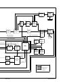
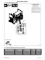
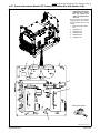
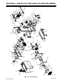
SECTION 5 − THEORY OF OPERATION
5
4
Boost
Input
Inductor
L1
Boost
Snubber
Inductor
L2
7
2
1 Phase
or
3 Phase
Input
Power
Inverter
Module
Mod2
8
Input
Pre-Regulator
Module
Mod1
1
6
9
Snubber
Resistor
Module
RM1
Bus
Capacitors
C12, C13
3
Power
Switch
S1
10
Power Interconnect Board
PC2
Current
Transformer
CT1
Bus Voltage
Input Rectifier Voltage
Input Boost Inductor
Current Feedback
Boost Gate Signal
20
Front Panel And Display Board PC3
21
21
Voltmeter
V
22
Arc
Control
Ammeter
A
23
Voltage/
Amperage
Adjust
27 ♦
Optional
Auxiliary Power
115 VAC
Receptacle
115 VAC
24 VAC
24
Remote 14-Pin Receptacle
RC50
Ribbon Cable
25
Process
Selector
Switch
TM-229 409 Page 14
26
Weld
Process
Control
Positive (+) Output Voltage Feedback
Negative (−) Output Voltage Feedback
Extreme 360
19
Output
Stabilizer
L3
16
17
11
12
Series
Capacitor
C15
Work
18
Stick
Boost
Inductor
L4
Stick
Boost
Relay
CR1
Stick
Boost
Rectifier
SR1
Output
Diodes
D1 & D2
Inverter Gating Signals
35
Fan
Motor
FM1
28
31
29
30
37
Secondary
Heatsink
Thermistor
RT-1
Control/Auxiliary Power
PC1
665
VAC
Circuit
Breaker
CB1
34
115 VAC
Electrode
38
Primary
Heatsink
Thermistor
RT-2
34 VAC
Center
Tapped
Control
Transformer
T2
33
Circuit
Breaker
CB2
36 ♦
Optional
Gas
Solenoid
GS1
Positive (+)
Weld
Output
Receptacle
Inverter
Control
Auxiliary
Power
Module
Boost
Control
32
Output
Current
Sensor
HD1
Output Current Feedback
Main Transformer
Current Feedback
15
14
13
Main
Transformer
T1
15
Negative (−)
Weld
Output
Receptacle
24 VAC
115 VAC
Control Circuit
Primary Circuit
Weld Circuit
♦
Extreme 360
Optional
TM-229 409 Page 15
Theory Of Operation Components
1
Primary Input Power
Single or Three-Phase AC primary
power supply.
2
Power Switch S1
12 Main Transformer T1
Switching action of IGBTs in MOD2
creates the AC voltage source for
T1 primary. T1 secondary outputs
supply power to the weld circuit.
Provides on/off control of primary
input power to welding power
source.
13 Output Diodes D1, D2
3
14 Output Current Sensor HD1
Power Interconnect Board
PC2
Provides electrical connections for
L1, L2, MOD1, MOD2, RM1, C12 &
C13. Precharge and bleeder resistors and snubber capacitors are
mounted on PC2.
4
Boost Input Inductor L1
Rectifies the main secondary output of T1.
Provides weld output current feedback to PC1.
15 Positive (+) and Negative (−)
Weld Output Receptacles
Provide weld output and allow
changing of output polarity.
16 Stick Boost Relay CR1
Required to boost input rectifier
voltage to bus voltage.
Provides on/off control of Stick
boost output circuit.
5
17 Stick Boost Inductor L4
Boost Snubber Inductor L2
Required to ensure soft−switching
of the boost IGBT located in
MOD1.
Limits current in the Stick boost
output circuit.
6
Rectifies the Stick boost secondary output of T1.
Inverter Module MOD2
Contains the main inverter IGBTs,
snubber IGBTs, main boost diode,
and two boost snubber diodes.
7
Input Pre−Regulator Module
MOD1
Contains the input rectifier diodes,
boost IGBT, and one boost snubber diode.
8
Snubber Resistor Module
RM1
18 Stick Boost Rectifier SR1
19 Output Stabilizer L3
Filters or smooths the DC weld output current.
20 User Interface Board PC3
Consists of Voltmeter V, Ammeter
A, Arc Control, Voltage/Amperage
Adjust, Remote 14−pin receptacle,
Process Selector Switch, and
Weld Process Control.
21 Voltmeter V, Ammeter A
Contains one boost snubber resistor and one inverter snubber resistor.
See Sections 4-1, Front Panel
Controls and 4-2, Meter Functions.
9
Controls Dig in Stick process or Inductance in MIG process. See
Section 4-1, Front Panel Controls.
Bus Capacitors C12 & C13
Stores energy and filters the DC
bus voltage for input boost and inverter.
10 Current Transformer CT1
Provides T1 current feedback to
PC1. Used to protect inverter
IGBTs in case of T1 primary overcurrent.
11 Series Capacitor C15
Provides protection against T1 saturation. Saturation occurs when
the voltage across the transformer
is not balanced. The unbalanced
voltage appears as a DC offset
voltage across the transformer and
can cause a primary overcurrent.
The capacitor protects against this
condition by blocking the DC offset.
TM-229 409 Page 16
22 Arc Control
23 Voltage/Amperage Adjust
Selects weld output voltage or amperage level. See Section 4-1,
Front Panel Controls.
24 Remote 14-Pin Receptacle
RC50
Provides connection to auxiliary
equipment. See Sections 4-1,
Front Panel Controls, and 3-6, Remote 14 Receptacle Information.
25 Process Selector Switch
Selects weld process. See Section 4-1, Front Panel Controls.
26 Weld Process Control
Controls weld output by automatically adjusting output current command signal to Inverter Control.
27 Optional Auxiliary Power 115
VAC Receptacle
Provides connection for auxiliary
equipment to welding power
source.
28 Control/Auxiliary Power
Board PC2
Contains the boost control, auxiliary power module, and inverter control.
29 Boost Control
Controls switching of boost IGBT
in MOD1 to regulate L1 current and
the DC bus voltage.
30 Auxiliary Power Module
Contains power supply for boost
control power, and inverter IGBTs
to create AC voltage source for T2
primary.
31 Inverter Control
Controls the main inverter and
snubber IGBTs within MOD2.
Regulates the weld output current
to the value received from weld
process controller. Provides power
to PC3. Drives fan motor and gas
valve. Provides interface between
primary and secondary thermistors and PC3.
32 Circuit Breaker CB1
Provides overload protection for
remote 14-pin 115 VAC power, and
optional 115 VAC receptacle.
33 Circuit Breaker CB2
Provides overload protection for
remote 14-pin 24 VAC power.
34 Control Transformer T2
Provides power to inverter control
on PC1, remote 14-pin receptacle,
and optional 115 VAC receptacle.
35 Fan Motor FM1
Provides cooling of heatsinks and
components mounted inside wind
tunnel. The fan motor is thermostatically controlled and only runs
when cooling is needed. Once unit
is cooled to proper temperature,
fan will continue to run for ten minutes.
36 Optional Gas Solenoid GS1
Provides on/off flow of shielding
gas to the arc while TIG welding.
37 Secondary Heatsink
Thermistor RT-1
Monitors temperature of secondary heatsink for fan motor control
and overtemperature shutdown.
38 Primary Heatsink Thermistor
RT-2
Monitors temperature of primary
heatsink for fan motor control and
overtemperature shutdown.
Extreme 360
SECTION 6 − TROUBLESHOOTING
6-1. Checking Unit Before Applying Power
. See Section 6-24 for test points and values and Section
9 for parts location.
Y Discharge input capacitors according to Section 6-3 and be sure voltage is near zero before touching any parts.
Y Before applying power to unit, complete the pre-power flowchart in Section 6-2 to avoid causing further damage.
Y Although control/auxiliary power board PC1 and power interconnect board PC2 are briefly checked in the pre-power flowchart, more
complete tests may be needed later for these parts. This procedure is simply to get a basic okay to power up unit.
NOTE
The pre-power flowchart should be followed if any of the following conditions exist:
the symptoms are unknown;
the unit is completely inoperative;
visual damage is found on any of the following components: capacitors C12 and
C13, control board PC1, IGBT power modules MOD1 and MOD2, interconnecting
board PC2, or input rectifier SR1;
there is no output or limited output.
Extreme 360
TM-229 409 Page 17
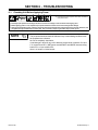
PRE-POWER CHECKS
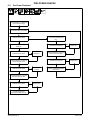
6-2.
Pre-Power Flowchart
Complete Section 6-3, Measuring
Input Capacitor Voltage.
Complete Sections 6-4 Thru 6-7
For Modules MOD1 And MOD2.
All Measurements Pass?
Complete Sections 6-13 Thru
6-18, Control/Auxiliary Board
PC1.
NO
YES
Complete Section 6-8 For Power
Switch S1.
All Measurements Pass?
NO
Replace PC1.
YES
All Measurements Pass?
NO
Replace S1.
Complete Sections 6-19 and 6-20,
Power Interconnect PC2.
YES
NO
Complete Sections 6-9 and 6-10,
Output Diodes D1 & D2.
All Measurements Pass?
Replace PC2.
YES
All Measurements Pass?
NO
Replace
D1 & D2.
Replace Modules MOD1 &
MOD2. (See Module Field Kit
Instructions.)
YES
Complete Sections 6-11 and 6-12,
Stick Boost Rectifier SR1.
NO
All Measurements Pass?
Replace SR1.
YES
Pre-power flowchart complete.
Complete Section 6-31,
Checking Unit After Servicing.
TM-229 409 Page 18
Extreme 360
PRE-POWER CHECKS
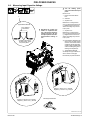
6-3. Measuring Input Capacitor Voltage
Y Turn Off welding power
source, and disconnect input
power.
Remove cover
5
Power Interconnect Board
PC2
2
Voltmeter
3
Capacitor C12
Measure the dc voltage across
C12 (+) Positive Terminal and C12
(−) Negative Terminal on PC2 as
shown until voltage drops to near
0 (zero) volts.
Typical Bleeder Resistor
25 to 1000 ohm,
5 watt resistor
1
Y Significant DC voltage can
remain on capacitors after
unit is Off. Always check the
voltage as shown to be sure
the input capacitors have discharged before working on
unit.
4
Capacitor C13
Measure the dc voltage across
C13 (+) Positive Terminal and C13
(−) Negative Terminal on PC2 as
shown until voltage drops to near
0 (zero) volts.
. If the capacitor voltage does not
#16 AWG 1000 volts dc
insulation rating, approx.
3 in (76 mm) leads
drop to near zero after several
minutes, use a bleeder resistor
of between 25 and 1000 ohms,
at least 5 watts, #16 AWG 1000
volts dc insulating rating wire to
discharge the capacitor(s) .
5
Typical Bleeder Resistor
An example of a typical bleeder resistor is shown on this page.
Proceed with pre-power flowchart.
4
1
2
3
1
2
Positive (+) lead to C13 (+) terminal,
Negative (−) lead to C13 (−) terminal
Positive (+) lead to C12 (+) terminal,
Negative (−) lead to C12 (−) terminal
Test Equipment Needed:
Ref. 803 721-B / 907 161
Extreme 360
TM-229 409 Page 19
PRE-POWER CHECKS
6-4. Input Pre-Regulator Module (MOD1)
Test Equipment Needed:
Y Read and follow safety
information in Section 6-1
before proceeding.
Y Wear an earth grounded
wrist strap when performing pre-power checks. Remove wrist strap before
performing any checks or
procedures with power applied to the machine.
1
. Board layout may differ from
that shown.
1
MOD1
Visually inspect MOD1 for damage.
2
Component Side Of Board
10
3
2
3
4
5
6
7
8
9
10
−BUS
D12 Cathode
AC1
AC2
AC3
L1
L1-L2
TP1
+BUS
Check all measurements for Input
Pre−Regulator Module (MOD1)
(see Section 6-5).
9
4
If all measurements passed,
MOD1 is OK. Continue to the end
of the pre−power flowchart (see
Section 6-2).
8
5
6
7
Ref. 907 161 / 225 065-A
6-5. Input Pre-Regulator Module (MOD1) Test Point Values
Input Pre-Regulator Module MOD1
DVM Positive Lead
DVM Negative Lead
DVM Diode
DVM Ohms
Boost IGBT
−BUS
L1-L2
0.20 - 0.90
N/A
Boost IGBT (w/Plug Removed From RC3)
D12 Cathode
−BUS
N/A
100k
Boost Snubber Diode
L1-L2
TP1 (C6 and C7)
0.20 - 0.90
N/A
Input SCR
AC1
L1
0.20 - 0.90
N/A
Input SCR
AC2
L1
0.20 - 0.90
N/A
Input SCR
AC3
L1
0.20 - 0.90
N/A
Input Diode
−BUS
AC1
0.20 - 0.90
N/A
Input Diode
−BUS
AC2
0.20 - 0.90
N/A
Input Diode
−BUS
AC3
0.20 - 0.90
N/A
TM-229 409 Page 20
Extreme 360
PRE-POWER CHECKS
6-6. Inverter Module (MOD2)
Y Read and follow safety
information in Section 6-1
before proceeding.
Test Equipment Needed:
Y Wear an earth grounded
wrist strap when performing
pre-power checks. Remove
wrist strap before performing any checks or procedures with power applied to
the machine.
1
. Board layout may differ from
that shown.
1
MOD2
Visually inspect MOD2 for damage.
14
13
Component Side Of Board
12
2
3
11
10
9
4
8
7
6
2
3
4
5
6
7
8
9
10
11
12
13
14
−BUS
TP2
TP1
L2
TP4
HF-XFMR
D4
D2
TP3
D8
D10
D11
+BUS
Check all measurements for Inverter Module (MOD2) (see Section
6-7).
If all measurements passed, MOD2
is OK. Continue to the end of the
pre−power flowchart (see Section
6-2).
5
Ref. 907 161 / 225 065-A
6-7. Inverter Module (MOD2) Test Point Values
Inverter Module MOD2
DVM Positive Lead
DVM Negative Lead
DVM Diode
DVM Ohms
Boost Snubber Diode
TP1 (C6 and C7)
TP4 (C1)
0.20 - 0.90
N/A
Boost Snubber Diode
L2
TP4 (C1)
0.20 - 0.90
N/A
Main Boost Diode
TP4 (C1)
+BUS
0.20 - 0.90
N/A
Inverter IGBT
HF-XFMR
+BUS
0.20 - 0.90
N/A
Inverter IGBT
−BUS
HF-XFMR
0.20 - 0.90
N/A
Snubber IGBT
TP2 (D11 Cathode)
HF-XFMR
0.20 - 0.90
N/A
Snubber IGBT
TP2 (D11 Cathode)
TP3 (C2)
0.20 - 0.90
N/A
Inverter IGBT Gate
D2 Cathode
HF-XFMR
N/A
100k
Inverter IGBT Gate
D4 Cathode
−BUS
N/A
100k
Snubber IGBT Gate
(w/Plug Removed From RC1)
D10 Cathode
TP2 (D11 Cathode)
N/A
100k
Snubber IGBT Gate
(w/Plug Removed From RC1)
D8 Cathode
TP2 (D11 Cathode)
N/A
100k
Extreme 360
TM-229 409 Page 21
PRE-POWER CHECKS
6-8. Power Switch (S1)
Y Read and follow safety
information in Section 6-1
before proceeding.
1
1
Power Switch S1
Visually inspect S1 for damage.
Check switch mechanical operation by turning switch On and Off
several times. Switch should snap
sharply between the On and Off
positions.
Electrical Schematic
Check switch electrical operation
by checking continuity across S1
contacts with switch in the On position. With switch in the Off position,
ohmmeter should read open.
Replace switch if necessary.
Continue to the end of the pre−power flowchart (see Section 6-2).
Test Equipment Needed:
Ref. 907 161 / Ref. 183 484
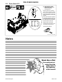
Notes
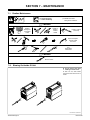
Work like a Pro!
Pros weld and cut
safely. Read the
safety rules at
the beginning
of this manual.
TM-229 409 Page 22
Extreme 360
PRE-POWER CHECKS
6-9. Output Diodes D1, D2
Y Read and follow safety
information in Section 6-1
before proceeding.
1
2
Diode D1
Diode D2
Visually inspect D1 and D2 for damage.
Check all measurements for output
diodes D1 and D2 (see Section
6-10).
+
Weld Output
Receptacles
If all measurements passed, the
output diodes D1 and D2 are OK.
Continue to the end of the pre−power flowchart (see Section 6-2).
−
Test Equipment Needed:
2
1
Diodes D1, D2
Ref. 907 161
6-10. Output Diodes D1, D2 Test Point Values
Output Diodes D1 And D2
DVM Positive Lead
DVM Negative Lead
DVM Diode
DVM Ohms
D1
Terminal Anode
Secondary Heatsink
0.10 - 0.90
N/A
D2
Terminal Anode
Secondary Heatsink
0.10 - 0.90
N/A
Extreme 360
TM-229 409 Page 23
PRE-POWER CHECKS
6-11. Stick Boost Rectifier (SR1)
Y Read and follow safety
information in Section 6-1
before proceeding.
1
Stick Boost Rectifier SR1
Visually inspect SR1 for damage.
Check all measurements for stick
boost rectifier SR1 (see Section
6-12).
If all measurements passed, SR1 is
OK. Continue to the end of the pre−
power flowchart (see Section 6-2).
1
3
4
2
1
Test Equipment Needed:
Ref. 907 161
6-12. Stick Boost Rectifier (SR1) Test Point Values
Stick Boost Rectifier SR1
DVM Positive Lead
DVM Negative Lead
DVM Diode
DVM Ohms
SR1
Terminal 2
Terminal 1
0.20 - 0.90
N/A
SR1
Terminal 4
Terminal 1
0.20 - 0.90
N/A
SR1
Terminal 3
Terminal 2
0.20 - 0.90
N/A
SR1
Terminal 3
Terminal 4
0.20 - 0.90
N/A
TM-229 409 Page 24
Extreme 360
PRE-POWER CHECKS
Notes
OHM’S LAW
VOLTAGE =
CURRENT X RESISTANCE
CURRENT = VOLTAGE
RESISTANCE
RESISTANCE = VOLTAGE
CURRENT
Extreme 360
TM-229 409 Page 25
PRE-POWER CHECKS
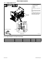
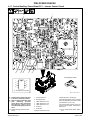
6-13. Control/Auxiliary Power Board PC1 − Auxiliary Power Circuit
5
1
8
11
6
7
4
13
12
9
10
2
3
1
8
2
7
3
6
4
5
Test Equipment Needed:
. Pin sequence of IC chips.
Ref. 217 184-F / 907 161
Y Read and follow safety information
in Section 6-1 before proceeding.
Y Wear an earth grounded wrist strap
when
performing
pre-power
checks. Remove wrist strap before
performing any checks or procedures with power applied to the machine.
. Remove all plugs from PC1 before
1
2
testing.
Control Board PC1
Receptacle RC2
TM-229 409 Page 26
3
4
5
6
7
8
9
10
11
12
13
Receptacle RC3
Receptacle RC5
IGBT Gate Drive IC U1
IGBT Gate Drive IC U4
IGBT Gate Drive IC U5
Diode D37
Diode D38
Diode D39
Diode D42
Diode D43
Diode D44
Unplug all connections to PC1.
Visually inspect PC1 for damage.
Check all measurements for PC1 Auxiliary
Power, Pre-Regulator and Inverter Control
(see Sections 6-14 thru 6-18).
If all measurements passed, continue to
the end of the pre-power flowchart (see
Section 6-2).
. If
any measurements failed, replace
PC1.
Extreme 360
PRE-POWER CHECKS
6-14. Control/Auxiliary Power Board PC1 − Auxiliary Power Circuit Test Point Values
60Hz Auxiliary Power Bridge
DVM Positive Lead
DVM Negative Lead
DVM Diode
DVM Ohms
Auxiliary Bridge IGBT
RC5 Pin 3
RC2 Pin 1
0.20 - 0.90
N/A
Auxiliary Bridge IGBT
RC5 Pin 1
RC2 Pin 1
0.20 - 0.90
N/A
Auxiliary Bridge IGBT
RC3 Pin 6 (PRECOM)
RC5 Pin 3
0.20 - 0.90
N/A
Auxiliary Bridge IGBT
RC3 Pin 6 (PRECOM)
RC5 Pin 1
0.20 - 0.90
N/A
Auxiliary Bridge IGBT Gate Drive IC U1
RC3 Pin 6 (PRECOM)
U1 Pin 5
0.20 - 0.90
N/A
Auxiliary Bridge IGBT Gate Drive IC U1
U1 Pin 5
U1 Pin 6
0.20 - 0.90
N/A
Auxiliary Bridge IGBT Gate Drive IC U1
RC3 Pin 6 (PRECOM)
U1 Pin 7
0.20 - 0.90
N/A
Auxiliary Bridge IGBT Gate Drive IC U1
U1 Pin 7
U1 Pin 6
0.20 - 0.90
N/A
Auxiliary Bridge IGBT Gate Drive IC U4
RC5 Pin 1
U5 Pin 7
0.20 - 0.90
N/A
Auxiliary Bridge IGBT Gate Drive IC U5
RC5 Pin 3
U4 Pin 7
0.20 - 0.90
N/A
D37
D37 Anode
D37 Cathode
0.20 - 0.90
N/A
D38
D38 Anode
D38 Cathode
0.20 - 0.90
N/A
D39
D39 Anode
D39 Cathode
0.20 - 0.90
N/A
D42
D42 Anode
D42 Cathode
0.20 - 0.90
N/A
D43
D43 Anode
D43 Cathode
0.20 - 0.90
N/A
D44
D44 Anode
D44 Cathode
0.20 - 0.90
N/A
Notes
Work like a Pro!
Pros weld and cut
safely. Read the
safety rules at
the beginning
of this manual.
Extreme 360
TM-229 409 Page 27
PRE-POWER CHECKS
6-15. Control/Auxiliary Power Board PC1 − Pre-Regulator Control Circuit
1
7
4
10
11
12
5
8
9
14
13
6
2
3
1
8
2
7
3
6
4
5
Test Equipment Needed:
. Pin sequence of IC chips.
Ref. 217 184-F / 907 161
Y Read and follow safety information
in Section 6-1 before proceeding.
Y Wear an earth grounded wrist strap
when
performing
pre-power
checks. Remove wrist strap before
performing any checks or procedures with power applied to the machine.
. Remove all
1
2
plugs from PC1 before
testing.
Control Board PC1
Receptacle RC2
TM-229 409 Page 28
3
4
5
6
7
8
9
10
11
12
13
Receptacle RC3
Receptacle RC5
IGBT Gate Drive IC U6
Diode D18
Diode D41
Diode D46
Diode D47
Diode D49
Diode D50
Diode D51
Diode D52
14 Diode D53
Unplug all connections to PC1.
Visually inspect PC1 for damage.
Check all measurements for PC1 Auxiliary
Power, Pre-Regulator and Inverter Control
(see Sections 6-14 thru 6-18).
If all measurements passed, continue to
the end of the pre-power flowchart (see
Section 6-2).
. If any measurements failed, replace
PC1.
Extreme 360
PRE-POWER CHECKS
6-16. Control/Auxiliary Power Board PC1 − Pre-Regulator Control Circuit Test Point Values
Pre-Regulator Control
DVM Positive Lead
DVM Negative Lead
DVM Diode
DVM Ohms
Buck IGBT
U6 Pin 3
RC2 Pin 1
0.20 - 0.90
N/A
Buck Diode
RC3 Pin 6 (PRECOM)
U6 Pin 5 (BUCK-COM)
0.20 - 0.90
N/A
Buck IGBT Gate Drive IC U6
U6 Pin 6
U6 Pin 7 (BUCK+15V)
0.20 - 0.90
N/A
D18
D18 Anode
D18 Cathode
0.20 - 0.90
N/A
D41
D41 Anode
D41 Cathode
0.20 - 0.90
N/A
D46
D46 Anode
D46 Cathode
0.10 - 0.30
N/A
D47
D47 Anode
D47 Cathode
0.10 - 0.30
N/A
D49
D49 Anode
D49 Cathode
0.20 - 0.90
N/A
D50
D50 Anode
D50 Cathode
0.20 - 0.90
N/A
D51
D51 Anode
D51 Cathode
0.20 - 0.90
N/A
D52
D52 Anode
D52 Cathode
0.20 - 0.90
N/A
D53
D53 Anode
D53 Cathode
0.20 - 0.90
N/A
Boost IGBT Gate Drive
RC3 Pin 4 (BOOST−G)
RC3 Pin 2 (PRE+15V)
0.20 - 0.90
N/A
Boost IGBT Gate Drive
RC3 Pin 4 (BOOST−G)
RC3 Pin 3 (PRE−12V)
N/A
1.9k - 2.1k
Boost IGBT Gate Drive
RC3 Pin 3 (PRE−12V)
RC3 Pin 4 (BOOST−G)
0.20 - 0.90
N/A
Notes
Work like a Pro!
Pros weld and cut
safely. Read the
safety rules at
the beginning
of this manual.
Extreme 360
TM-229 409 Page 29
PRE-POWER CHECKS
6-17. Control/Auxiliary Power Board PC1 − Inverter Control Circuit
1
2
4
3
6
7
5
Test Equipment Needed:
1
8
2
7
3
6
4
5
. Pin sequence of IC chips.
Ref. 217 184-F / 907 161
Y Read and follow safety information
in Section 6-1 before proceeding.
Y Wear an earth grounded wrist strap
when
performing
pre-power
checks. Remove wrist strap before
performing any checks or procedures with power applied to the machine.
1
Control Board PC1
Visually inspect PC1 for damage.
2
Receptacle RC9
3
IGBT Gate Drive IC U13
4
IGBT Gate Drive IC U16
Check all measurements for PC1 Auxiliary
Power, Pre-Regulator and Inverter Control
(see Sections 6-14 thru 6-18).
5
IGBT Gate Drive IC U17
6
Diode D11
. Remove all plugs from PC1 before
7
Diode D20
testing.
TM-229 409 Page 30
Unplug all connections to PC1.
If all measurements passed, continue to
the end of the pre-power flowchart (see
Section 6-2).
. If any measurements failed, replace
PC1.
Extreme 360
PRE-POWER CHECKS
6-18. Control/Auxiliary Power Board PC1 − Inverter Control Circuit Test Point Values
Inverter Control
DVM Positive Lead
DVM Negative Lead
DVM Diode
DVM Ohms
Inverter IGBT Gate Drive IC U16
U16 Pin 5
RC9 Pin 4 (+15V)
0.20 - 0.90
N/A
Inverter IGBT Gate Drive IC U16
U16 Pin 7
RC9 Pin 4 (+15V)
0.20 - 0.90
N/A
Inverter IGBT Gate Drive IC U16
RC9 Pin 6 (GND)
U16 Pin 5
0.20 - 0.90
N/A
Inverter IGBT Gate Drive IC U16
RC9 Pin 6 (GND)
U16 Pin 7
0.20 - 0.90
N/A
Inverter IGBT Gate Drive IC U17
U17 Pin 5
RC9 Pin 4 (+15V)
0.20 - 0.90
N/A
Inverter IGBT Gate Drive IC U17
U17 Pin 7
RC9 Pin 4 (+15V)
0.20 - 0.90
N/A
Inverter IGBT Gate Drive IC U17
RC9 Pin 6 (GND)
U17 Pin 5
0.20 - 0.90
N/A
Inverter IGBT Gate Drive IC U17
RC9 Pin 6 (GND)
U17 Pin 7
0.20 - 0.90
N/A
Snubber IGBT Gate Drive IC U13
U13 Pin 5
RC9 Pin 4 (+15V)
0.20 - 0.90
N/A
Snubber IGBT Gate Drive IC U13
U13 Pin 7
RC9 Pin 4 (+15V)
0.20 - 0.90
N/A
Snubber IGBT Gate Drive IC U13
RC9 Pin 6 (GND)
U13 Pin 5
0.20 - 0.90
N/A
Snubber IGBT Gate Drive IC U13
RC9 Pin 6 (GND)
U13 Pin 7
0.20 - 0.90
N/A
D11
D11 Anode
D11 Cathode
0.20 - 0.90
N/A
D20
D20 Anode
D20 Cathode
0.20 - 0.90
N/A
Notes
Work like a Pro!
Pros weld and cut
safely. Read the
safety rules at
the beginning
of this manual.
Extreme 360
TM-229 409 Page 31
PRE-POWER CHECKS
6-19. Power Interconnect Board (PC2)
1
Test Equipment Needed:
22
21
23
10
18 17
15
5
16
20
9
19
11
3
12
4
2
6
13
14
7
8
Ref. 907 161 / 225 065-A
Y Read and follow safety information
in Section 6-1 before proceeding.
Y Wear an earth grounded wrist strap
when
performing
pre-power
checks. Remove wrist strap before
performing any checks or procedures with power applied to the machine.
1 Power Interconnect Board PC2
2 Resistor R10
3 Resistor R11
4 Resistor R12
5 Resistor R14
6 AC1
7 AC2
8 AC3
TM-229 409 Page 32
9
10
11
12
13
14
15
16
17
18
19
20
21
22
Q1
Q2
Diode D1
Diode D2
Diode D3
Diode D4
Diode D8
Diode D9
Diode D10
Diode D11
Diode D12
Diode D13
Center Bus
−BUS
23 +BUS
. Remove all
plugs from PC2 before
testing.
Visually inspect PC2 for damage.
Check all measurements for PC2.
If all measurements passed, continue to
the end of the pre-power flowchart (see
Section 6-2).
. If any measurements failed, replace
PC2.
Y Pre-power checks are now complete. Remove earth grounded wrist
strap before performing any checks
or procedures with power applied to
the machine.
Extreme 360
PRE-POWER CHECKS
6-20. Power Interconnect Board (PC2) Test Point Values
Power Interconnect Board PC2
DVM Positive Lead
DVM Negative Lead
DVM Diode
DVM Ohms
Pre-Charge Resistor R14
R14 Bottom
R14 Top
N/A
200
SCR Gate Resistor R10
R10 Left
R10 Right
N/A
10 - 16.5
SCR Gate Resistor R11
R11 Left
R11 Right
N/A
10 - 16.5
SCR Gate Resistor R12
R12 Left
R12 Right
N/A
10 - 16.5
Pre-Charge Diode D5
AC3
R14 Top
0.20 - 0.90
N/A
Pre-Charge Diode D6
AC2
R14 Top
0.20 - 0.90
N/A
Pre-Charge Diode D7
AC1
R14 Top
0.20 - 0.90
N/A
Boost Gate Protection Diode D12
D12 Anode
D12 Cathode
0.20 - 0.90
N/A
Boost Gate Protection Diode D13
D13 Anode
D13 Cathode
0.20 - 0.90
N/A
Inverter Gate MOSFET Q1
Q1-S (Source)
Q1-D (Drain)
0.20 - 0.90
N/A
Inverter Gate MOSFET Q2
Q2-S (Source)
Q2-D (Drain)
0.20 - 0.90
N/A
Inverter Gate Protection Diode D1
D1 Anode
D1 Cathode
0.20 - 0.90
N/A
Inverter Gate Protection Diode D2
D2 Anode
D2 Cathode
0.20 - 0.90
N/A
Inverter Gate Protection Diode D3
D3 Anode
D3 Cathode
0.20 - 0.90
N/A
Inverter Gate Protection Diode D4
D4 Anode
D4 Cathode
0.20 - 0.90
N/A
Snubber Gate Protection Diode D8
D8 Anode
D8 Cathode
0.20 - 0.90
N/A
Snubber Gate Protection Diode D9
D9 Anode
D9 Cathode
0.20 - 0.90
N/A
Snubber Gate Protection Diode D10
D10 Anode
D10 Cathode
0.20 - 0.90
N/A
Snubber Gate Protection Diode D11
D11 Anode
D11 Cathode
0.20 - 0.90
N/A
Bleeder Resistor R1
(Prior to LF278160)
Center Bus
−BUS
N/A
28k - 32k
Bleeder Resistor R1 (Eff W/LF278161)
Center Bus
−BUS
N/A
37k - 41k
Bleeder Resistor R8
(Prior to LF278160)
+BUS
Center Bus
N/A
28k - 32k
Bleeder Resistor R8 (Eff W/LF278161)
+BUS
Center Bus
N/A
37k - 41k
. Bleeder resistor measurements
may require several minutes to
complete.
Notes
Extreme 360
TM-229 409 Page 33
Always check unit before applying power (see Sections 6-1 thru 6-18).
6-21. Troubleshooting Table
. See Section 6-24 for test points and values and
Section 9 for parts location.
. Use MILLER Testing Booklet (Part No. 150 853)
when servicing this unit.
Trouble
No weld output; unit completely
inoperative.
Remedy
Follow Pre-Power Flowchart, and replace any failed components (see Section 6-2).
Place line disconnect switch in On position (see Section 3-2 or 3-3).
Check and replace line fuse(s), if necessary, or reset circuit breaker (see Sections 3-2 and 3-3).
Check for proper input power connections and check condition of power cord
(see Section 3-2 or 3-3).
Check continuity of Power switch S1 and replace if necessary (see Section 6-8).
Check control transformer T2 for signs of winding failure. Check continuity across windings, and
check for proper connections. Check secondary voltages. Replace T2 if necessary.
Check control/auxiliary power board PC1 and connections, and replace if necessary (see Pre-Power
Checks in Sections 6-13 thru 6-18, and also see Section 6-25).
Check power interconnect board PC2 and connections, and replace if necessary (see Pre-Power
Checks in Sections 6-13 thru 6-18, and also see Section 6-27).
Check front panel/display board PC3 and connections, and replace if necessary (see Section 6-29).
No weld output; meter display On.
Follow Pre-Power Flowchart and replace any failed components (see Section 6-2).
Unit overheated and HELP 3 or HELP 5 screen is displayed. Allow unit to cool with fan On
(see Section 6-22).
If a remote accessory is connected to remote 14 receptacle RC50:
Check accessory contact closure (continuity), and replace accessory if necessary.
Check accessory amperage control potentiometer resistance and connections,
and replace accessory if necessary.
Check input and output voltages of hall device HD1 (see Section 6-24). Replace HD1 if necessary.
Check control/auxiliary power board PC1 and connections, and replace if necessary (see Pre-Power
Checks in Sections 6-13 thru 6-18, and also see Section 6-25).
Check front panel/display board PC3 and connections, and replace if necessary (see Section 6-29).
Low weld output with no control.
Check input and output voltages of hall device HD1 (see Section 6-24). Replace HD1 if necessary.
Check control/auxiliary power board PC1 and connections, and replace if necessary (see Pre-Power
Checks in Sections 6-13 thru 6-18, and also see Section 6-25).
Check front panel/display board PC3 and connections, and replace if necessary (see Section 6-29).
Maximum weld output with no control.
Check input and output voltages of hall device HD1 (see Section 6-24). Replace HD1 if necessary.
Check control/auxiliary power board PC1 and connections, and replace if necessary (see Pre-Power
Checks in Sections 6-13 thru 6-18, and also see Section 6-25).
Check front panel/display board PC3 and connections, and replace if necessary (see Section 6-29).
Limited output and low open circuit
voltage (OCV).
Check for proper input and output connections
If a remote accessory is connected to remote 14 receptacle RC50:
Check accessory contact closure (continuity), and replace accessory if necessary.
Check accessory amperage control potentiometer resistance and connections,
and replace accessory if necessary.
Check input and output voltages of hall device HD1 (see Section 6-24). Replace HD1 if necessary.
Check control/auxiliary power board PC1 and connections, and replace if necessary (see Pre-Power
Checks in Sections 6-13 thru 6-18, and also see Section 6-25).
Check front panel/display board PC3 and connections, and replace if necessary (see Section 6-29).
Check if Low Open Circuit Voltage Stick Mode is enabled (see Section 6-23).
TM-229 409 Page 34
Extreme 360
Always check unit before applying power (see Sections 6-1 thru 6-18).
Trouble
Erratic or improper weld output.
Remedy
Use proper size and type of weld cable (see Section 3-4).
Clean and tighten all weld connections.
Check for proper input and output connections.
Replace electrode.
If a remote accessory is connected to remote 14 receptacle RC50:
Check all remote accessory connections (proper pin/socket alignment).
Check accessory amperage control potentiometer resistance and connections,
and replace if necessary.
Check input and output voltages of hall device HD1 (see Section 6-24). Replace HD1 if necessary.
Check control/auxiliary power board PC1 and connections, and replace if necessary (see Pre-Power
Checks in Sections 6-13 thru 6-18, and also see Section 6-25).
Check front panel/display board PC3 and connections, and replace if necessary (see Section 6-29).
Fan motor does not run after approximately four minutes of operation at
rated load.
Check and clear blocked fan blade
Check receptacle wiring and connections. Check thermistors RT-1 and RT-2 (see Section 6-24).
. Fan motor FM1 starts and meters display HELP-2 when RT-1 or RT-2 is disconnected from PC1.
When RT-1 or RT-2 is reconnected, the meter displays change but the fan continues to run (see Section 6-22).
Check fan motor FM (see Section 6-24) and replace fan motor if necessary.
Wandering arc; poor control of arc
direction
direction.
Use proper size tungsten.
Use properly prepared tungsten.
Reduce gas flow rate.
Tungsten electrode oxidizing and not
remaining bright after conclusion of
weld.
Shield weld zone from drafts.
Increase postflow time.
Check and tighten all gas fittings.
Water in torch. Refer to torch manual.
Extreme 360
TM-229 409 Page 35
Always check unit before applying power (see Sections 6-1 thru 6-18).
6-22. Voltmeter/Ammeter Diagnostics
1
2
3
V
A
HE.L
P−1
V
A
HE.L
P−2
V
A
HE.L
P−3
. All directions are in reference to the front
of the unit. All circuitry referred to is located inside the unit.
1 Help 1 Display
Indicates a malfunction in the primary power
circuit caused by an overcurrent condition in
the primary IGBT switching circuit. If this display is shown, complete the Pre-Power Flowchart in Section 6-2.
2 Help 2 Display
Indicates a malfunction in the thermal protection circuit. The unit has detected a shorted or
open thermistor. If this display is shown, verify
thermistors RT-1 and RT-2 are plugged into
circuit board PC1 and check thermistor input
values on circuit board PC3 (see Section
6-29).
TM-229 409 Page 36
3
4
5
6
V
A
HE.L
P−5
V
A
HE.L
P−6
V
A
HE.L
P−8
Help 3 Display
Indicates the left side of the unit has overheated. The unit has shut down to allow the
fan to cool it (see Section 2-3). Operation will
continue when the unit has cooled.
4
Help 5 Display
Indicates the right side of the unit has overheated. The unit has shut down to allow the
fan to cool it (see Section 2-3). Operation will
continue when the unit has cooled.
5
Help 6 Display
Indicates operation at maximum input current.
The unit has a maximum allowable input current limit. As the line voltage decreases, the
required input current increases. If the line
voltage is too low, the output power is limited
by the input current. When this limit is
reached, the unit automatically reduces output power to continue operation. If this display
is shown, have a qualified electrician check
the input voltage.
6
Help 8 Display
Indicates a malfunction in the secondary power circuit of the unit. The unit has detected a
high open circuit voltage condition. If this display is shown, complete the Pre-Power Flowchart in Section 6-2, Check for proper connection of bypass capacitors C6 and C7 (see
Figure 8-2). Check operation of control relay
CR1 (see Section 6-24).
Extreme 360
Always check unit before applying power (see Sections 6-1 thru 6-18).
6-23. Enabling Low Open Circuit Voltage Stick Mode (Optional)
Y Disconnect and lockout/tagout input power before removing cover.
Follow this procedure to modify the
unit for low open circuit voltage
(OCV) when Stick welding. OCV is
reduced to about 15 volts dc.
1
1
2
2
Front Panel And Display
Board PC3
Switch SW1
Remove wrapper.
Place switch position 1 in the
Closed position by pressing actuator toward board.
Reinstall wrapper.
Follow the same arc starting procedures as described in Section 4-5.
907 161 / 217 181
Extreme 360
TM-229 409 Page 37
Always check unit before applying power (see Sections 6-1 thru 6-18).
6-24. Troubleshooting Circuit Diagram
Resistance Values
Voltage Readings
a)
Tolerance − ±10% unless specified
b)
Turn Off unit and disconnect input power
before checking resistance
a) Tolerance − ±10% unless specified
R1 thru R6, R9
Less than 1 ohm
b) Reference − single arrow: reference to
circuit common (lead 42); double arrow:
reference to points indicated
R7 and R8
190 − 210 ohms
c) Wiring Diagram − see Section 8
Y Discharge input capacitors according
to Section 6-3, and be sure voltage is
near zero before touching any parts.
V1
665 volts ac RMS
. No calibration available for voltmeter V or ammeter A.
V2, V3
17 volts ac RMS
V4
115 volts ac RMS
V5
24 volts ac RMS
V6, V7
470 volts dc
V8
115 volts ac RMS when FM is running
V9
24 volts dc when Relay is energized;
Relay energized in Stick mode with
output current greater than 10 amps
and preset current less than 225 amps
V10
24 volts dc when gas is flowing; see
Section 3-7 for gas valve operation
V11
+15 volts dc
V12
−15 volts dc
V13
1 volt dc per 100 amperes of weld
output
V14
72 volts dc open circuit voltage in
Scratch Start TIG, TIG, MIG, Pulse
MIG, CC, Stick and V-Sense feeder
modes.
. 14 volts dc in Stick mode when low
V5
open circuit voltage Stick mode is
enabled (See Section 6-23).
V4
14 volts dc in Lift-Arc TIG mode.
V3 V2
V1
See Section 6-30 for
RC50 information
See Section 6-29 for
PC3 information
V14
Test Equipment Needed:
Y HIGH VOLTAGE: Do not measure without
proper instrumentation.
. V1 thru V5 and V8 − use only true RMS meter
to obtain correct voltage reading.
TM-229 409 Page 38
Extreme 360
Always check unit before applying power (see Sections 6-1 thru 6-18).
See Section
6-27 for
PC2 information
R1
R2
R7
R8
R4
V6
R9
V7
R6
V14
R3
R5
Approx. 35K ohms
at 705 F (215 C)
{
V11
V12
V13
V8
V9
V10
See Section 6-25 for
PC1 information
211 328-E
Extreme 360
TM-229 409 Page 39
Always check unit before applying power (see Sections 6-1 thru 6-18).
6-25. Control/Auxiliary Power Board PC1 Testing Information (Use with Section 6-26)
9
12
Y Warning this procedure requires the machine to be electrically live. Significant DC
voltage can remain on capacitors after unit is Off.
5
1
Be sure plugs are secure before applying power. See Section 6-26 for
specific values during testing.
1
2
3
4
5
6
7
8
9
10
11
12
11
7
6
8
Inverter Control Board PC1
Receptacle RC1
Receptacle RC2
Receptacle RC3
Receptacle RC5
Receptacle RC6
Receptacle RC7
Receptacle RC8
Receptacle RC9
Receptacle RC10
Receptacle RC11
Receptacle RC12
3
10
2
4
Test Equipment Needed:
Ref. 217 184-F / 907 161
TM-229 409 Page 40
Extreme 360
Always check unit before applying power (see Sections 6-1 thru 6-18).
6-26. Control/Auxiliary Power Board PC1 Test Point Values
a) Tolerance − ±10% unless specified
PC1 Voltage Readings
Receptacle
RC1
RC2
Pin
Type
b) Reference − to circuit common
(lead 42) unless noted
Value
Y Do not measure − high voltage present.
Y High voltage present. Voltages on this receptacle can exceed 900 volts DC from chassis
(GND).
NOTE: All pins on this receptacle are referenced to the primary − Bus
1
Primary (+) bus; regulated to 940 volts dc with respect to primary (−) bus.
2
Not used
3
Not used
4
RC3
Input
Input
Primary (+) rectifier; rectified primary line volts.
Y High voltage present. Voltages on this receptacle can exceed 900 volts DC from chassis (GND).
NOTE: All pins on this receptacle are referenced to the primary − Bus
1
Input
2
Output
+15 volts dc; regulated with respect to primary (−) bus
3
Output
−12 volts dc; regulated with respect to primary (−) bus
4
Output
Do not measure − Boost IGBT gate drive signal
5
Do not measure − Boost IGBT gate drive signal return
6
Precom
Circuit common referenced to primary (−) bus
7
Precom
Circuit common referenced to primary (−) bus
8
Precom
Circuit common referenced to primary (−) bus
9
Input
10
11
Do not measure − HF transformer current sense CT; senses overcurrent in HF transformer primary
Do not measure − HF transformer current sense CT return
Output
12
RC5
Do not measure − Boost inductor current feedback; 1 volt dc per 16 amps of boost inductor current
Precharge relay coil return; 0 volts dc = relay contacts open, −12 volts dc = relay contacts closed
Not used
13
Input
Do not measure − Test point, used to test board only
14
Input
Do not measure − Test point, used to test board only
Y High voltage present. Voltages on this receptacle can exceed 900 volts DC from chassis
(GND).
NOTE: All pins on this receptacle are referenced to the primary − Bus
1
Output
2
3
Extreme 360
Control transformer primary; 665 volts ac rms with respect to RC5 pin 3
Not Used
Output
Control transformer primary; 665 volts ac rms with respect to RC5 pin 1
TM-229 409 Page 41
Always check unit before applying power (see Sections 6-1 thru 6-18).
Section 6-26. Control/Auxiliary Power Board PC1 Test Point Values (Continued)
Receptacle
Pin
Type
RC6
1
Input
Output reference; 1 volt dc per 425 amperes of weld output when machine is under load
2
Input
Voltage feedback; 1 volt dc per 10 volts dc of weld output
3
Output
4
5
Not Used
Input
Output enable; 0 volts dc = ON, +15 volts dc = OFF
Not Used
7
Boost relay coil return; +24 volts dc = relay contacts open, 0 volts dc = relay contacts closed
8
Gas valve coil return; +24 volts dc = valve closed (no gas flow), 0 volts dc = valve open
Input
10
11
Fan enable; +5 volts dc = fan on, −15 volts dc = fan off
Not Used
Output
12
RC8
Current feedback; 1 volt dc per 100 amperes of weld output
6
9
RC7
Value
HF transformer over current detect; 0 volts dc = OK, +5 volts dc = OVERCURRENT
Not Used
13
Input
+5 volts dc reference voltage for thermistors
14
GND
Circuit common referenced to chassis
15
Output
16
GND
17
Output
18
GND
19
Output
20
GND
21
Output
+24 volts dc, unregulated dc voltage with respect to GND
22
Output
+24 volts dc, unregulated dc voltage with respect to GND
23
Output
−24 volts dc, unregulated dc voltage with respect to GND
24
Output
−24 volts dc, unregulated dc voltage with respect to GND
1
Output
+5 volts dc reference voltage for secondary side thermistor
2
Input
1
Output
2
Input
TM-229 409 Page 42
Secondary side thermistor return; +2 volts dc at 25°C thermistor temperature
Circuit common referenced to chassis
Primary side thermistor return; +2 volts dc at 25°C thermistor temperature
Circuit common referenced to chassis
Foldback; decreases weld output if input bus voltage drops, 0 volts = OK, +15 volts dc 15Khz pwm
squarewave = foldback
Circuit common referenced to chassis
Secondary side thermistor return; +2 volts dc at 25°C thermistor temperature
+5 volts dc reference voltage for primary side thermistor
Primary side thermistor return; +2 volts dc at 25°C thermistor temperature
Extreme 360
Always check unit before applying power (see Sections 6-1 thru 6-18).
Section 6-26. Control/Auxiliary Power Board PC1 Test Point Values (Continued)
RC9
RC10
RC11
1
Output
Do not measure − Test point, used to test board only
2
Output
Do not measure − Test point, used to test board only
3
Input
Do not measure − Weld output current sensor signal
4
Output
+15 volts dc power to current sensor
5
Output
−15 volts dc power to current sensor
6
GND
1
Output
115 volts ac rms with respect to GND; power feed to fan
2
Output
Fan power return; measure with respect to RC10−1, 115 volts ac rms = fan on, 0 volts ac rms = fan off
3
Output
Do not measure − Test point, used to test board only
4
Output
Do not measure − Test point, used to test board only
1
Output
+24 volts output to boost relay coil
2
3
RC12
Weld output current sensor signal common
Boost relay coil return; +24 volts dc = relay contacts open, 0 volts dc = relay contacts closed
Output
+24 volts output to gas valve coil
4
Gas valve coil return; +24 volts dc = valve closed (no gas flow), 0 volts dc = valve open
1
Not Used
2
Input
3
Chassis
4
Input
5
6
Power source chassis; circuit common (GND) on this pin bonded to chassis thru wire
34 volts ac rms; measure with respect to RC12 pin 2, power supply used to create +24/−24 volts dc
Not Used
Input
7
8
34 volts ac rms; measure with respect to RC12 pin 4, power supply used to create +24/−24 volts dc
Center tap of 34 volt ac connected to circuit common (GND) on board
Not Used
Input
115 volts ac rms
Notes
OHM’S LAW
VOLTAGE =
CURRENT X RESISTANCE
CURRENT = VOLTAGE
RESISTANCE
RESISTANCE = VOLTAGE
CURRENT
Extreme 360
TM-229 409 Page 43
Always check unit before applying power (see Sections 6-1 thru 6-18).
6-27. Power Interconnect Board PC2 Testing Information (Use with Section 6-28)
Y Warning this procedure
requires the machine to be
electrically live. Significant DC voltage can
remain on capacitors after
unit is Off.
Be sure plugs are secure before
applying power. See Section
6-28 for specific values during
testing.
1
2
3
4
5
6
3
Power Interconnect Board
PC2
Receptacle RC1
Receptacle RC2
Receptacle RC3
Receptacle RC6
Receptacle RC7
1
4
2
6
Test Equipment Needed:
5
Ref. 225 065-A / 907 161
TM-229 409 Page 44
Extreme 360
Always check unit before applying power (see Sections 6-1 thru 6-18).
6-28. Power Interconnect Board PC2 Test Point Values
a) Tolerance − ±10% unless specified
PC2 Voltage Readings
Receptacle
RC1
RC2
Pin
Type
b) Reference − to circuit common
(lead 42) unless noted
Value
Y Do not measure − high voltage present.
Y High voltage present. Voltages on this receptacle can exceed 900 volts DC from chassis
(GND).
NOTE: All pins on this receptacle are referenced to the primary − Bus
1
Primary (+) bus; regulated to 940 volts dc with respect to primary (−) bus
2
Not Used
3
Not Used
4
RC3
Output
Output
Primary (+) rectifier; rectified primary line volts
Y High voltage present. Voltages on this receptacle can exceed 900 volts DC from chassis
(GND).
NOTE: All pins on this receptacle are referenced to the primary − Bus
1
RC6
Do not measure − Boost IGBT gate drive signal return
2
Input
Do not measure − Boost IGBT gate drive signal
3
Output
4
Input
5
Precom
Circuit common referenced to primary (−) bus
6
Precom
Circuit common referenced to primary (−) bus
7
Input
Precharge relay coil return; 0 volts dc = relay contacts open, −12 volts dc = relay contacts closed
8
Input
+15 volts dc; regulated with respect to primary (−) bus, +15 volts dc power to boost inductor current
sensor
Do not measure − Boost inductor current feedback
−12 volts dc; regulated with respect to primary (−) bus, −12 volts dc power to boost inductor current
sensor
Y High voltage present. Voltages on this receptacle can exceed 900 volts DC from chassis
(GND).
NOTE: All pins on this receptacle are referenced to the primary − Bus
Extreme 360
1
Snubber resistor1; input boost snubber, located in resistor module mounted to primary heat sink
2
Not Used
3
Snubber resistor2; inverter snubber, located in resistor module mounted to primary heat sink
4
Snubber resistor1; input boost snubber, located in resistor module mounted to primary heat sink
5
Not Used
6
Snubber resistor2; inverter snubber, located in resistor module mounted to primary heat sink
TM-229 409 Page 45
Always check unit before applying power (see Sections 6-1 thru 6-18).
Section 6-28. Power Interconnect Board PC2 Test Point Values (Continued)
Y High voltage present. The following terminals are used to interconnect the main power circuit with the primary supply, and with power circuit components not soldered in the pcb. Voltages on this receptacle can exceed
900 volts DC from chassis (GND).
Receptacle
Pin
Type
Value
AC1
Power
Primary AC mains phase 1; line voltage, measure with respect to AC2 or AC3
AC2
Power
Primary AC mains phase 2; line voltage, measure with respect to AC1 or AC3
AC3
Power
Primary AC mains phase 3; line voltage, measure with respect to AC1 or AC2
L1
Power
Input boost inductor; rectified line voltage, measure with respect to (−) bus
L1-L2
Power
Common point between input boost inductor and boost IGBT snubber inductor
L2
Power
Boost IGBT snubber inductor
HF-XFMR
Power
High frequency weld power transformer primary
C13 (+)
Power
(+) Bus; regulated to 940 volts dc with respect to (−) bus
C12 (−)
Power
(−) Bus; power circuit common
Center Bus
Power
Bus capacitors center point; regulated to 470 volts dc with respect to (−) bus
Notes
MATERIAL THICKNESS REFERENCE CHART
24 Gauge (.025 in)
22 Gauge (.031 in)
20 Gauge (.037 in)
18 Gauge (.050 in)
16 Gauge (.063 in)
14 Gauge (.078 in)
1/8 in (.125 in)
3/16 in (.188 in)
1/4 in (.25 in)
5/16 in (.313 in)
3/8 in (.375 in)
1/2 in (.5 in)
TM-229 409 Page 46
Extreme 360
Always check unit before applying power (see Sections 6-1 thru 6-18).
6-29. Front Panel/Display Board PC3 Testing Information (Use with Section 6-30)
2
1
Y Warning this procedure requires the machine to be
electrically live. Significant
DC voltage can remain on capacitors after unit is Off.
Be sure plugs are secure before applying power. See Section 6-30 for
specific values during testing.
1
2
3
4
Process Control Board PC3
Receptacle RC1
Receptacle RC2
Receptacle RC51
3
4
Test Equipment Needed:
Ref. 217 181-B / 907 161
Extreme 360
TM-229 409 Page 47
Always check unit before applying power (see Sections 6-1 thru 6-18).
6-30. Front Panel/Display Board PC3 Test Point Values
a) Tolerance − ±10% unless specified
PC3 Voltage Readings
b) Reference − to circuit common
(lead 42) unless noted
Receptacle
Pin
Type
RC1
1
Output
Output reference; 1 volt dc per 425 amperes of weld output when machine is under load
2
Output
Voltage feedback; 1 volt dc per 10 volts dc of weld output
3
Input
4
5
Not Used
Output
Output enable; 0 volts dc = ON, +15 volts dc = OFF
Not Used
7
Boost relay coil return; +24 volts dc = relay contacts open, 0 volts dc = relay contacts closed
8
Gas valve coil return; +24 volts dc = valve closed (no gas flow), 0 volts dc = valve open
Output
10
11
Fan enable; +5 volts dc = fan on, −15 volts dc = fan off
Not Used
Input
12
HF transformer over current detect; 0 volts dc = OK, +5 volts dc = OVERCURRENT
Not Used
13
Output
14
GND
Circuit common referenced to chassis
15
Input
Secondary side thermistor return; +2 volts dc at 25°C thermistor temperature
16
GND
Circuit common referenced to chassis
17
Input
Primary side thermistor return; +2 volts dc at 25°C thermistor temperature
18
GND
Circuit common referenced to chassis
19
Input
Foldback; decreases weld output if input bus voltage drops, 0 volts = OK, +15 volts dc 15Khz pwm
squarewave = foldback
20
GND
Circuit common referenced to chassis
21
Input
+24 volts dc, unregulated dc voltage with respect to GND, power feed to front panel pcb
22
Input
+24 volts dc, unregulated dc voltage with respect to GND, power feed to front panel pcb
23
Input
−24 volts dc, unregulated dc voltage with respect to GND, power feed to front panel pcb
24
Input
−24 volts dc, unregulated dc voltage with respect to GND, power feed to front panel pcb
1
Input
Negative weld output terminal; used for output voltage feedback
2
RC50
Current feedback; 1 volt dc per 100 amperes of weld output
6
9
RC2
Value
+5 volts dc reference voltage for thermistors
Not Used
3
Input
Positive weld output terminal; used for output voltage feedback
A
Output
23 volts ac RMS at 10 amps; 14−pin remote accessory power
B
Input
C
Output
D
GND
Remote command reference signal common
E
Input
Input signal from remote command; 0 to 10 volts dc
F
Output
TM-229 409 Page 48
Remote output enable; 0 volts ac = weld output off, 23 volts ac RMS = weld output on
Output signal to remote command reference; 0 to 10 volts dc
Current feedback; 1 volt dc per 100 amperes of weld output
Extreme 360
Always check unit before applying power (see Sections 6-1 thru 6-18).
Section 6-30. Front Panel/Display Board PC3 Test Point Values (Continued)
Receptacle
Pin
Type
RC50
G
GND
H
Output
Voltage feedback; 1 volt dc per 10 volts dc of weld output
I
Output
115 volts ac at 2 amps; 14−pin remote accessory power
J
Input
K
Chassis
L
Value
14−pin remote accessory power return
Remote output enable; 0 volts ac = weld output off, 115 volts ac = weld output on
Power source chassis
Not used
M
Input
N
Remote process select; 0 volts dc = CC, 15 volts dc = CV
Not used
6-31. Checking Unit Output After Servicing
1
Weld Output Terminals
Check open-circuit voltage between terminals according to Section 6-24 (voltage V-14)
If correct voltage is not present,
repeat troubleshooting procedures.
Reinstall cover and side panels if
removed.
1
803 691-C
Extreme 360
TM-229 409 Page 49
SECTION 7 − MAINTENANCE
7-1. Routine Maintenance
. Maintain more often
Y Disconnect power
before maintaining.
during severe conditions.
3 Months
Repair Or
Replace
Cracked
Cables
Replace
Damaged Or
Unreadable
Labels
Replace Cracked
Torch Body
Repair Or Replace
Cracked Cables
And Cords
Clean
And
Tighten Weld
Connections
6 Months
Blow Out Inside
7-2. Blowing Out Inside Of Unit
Y Do not remove case when
blowing out inside of unit.
To blow out unit, direct airflow
through front and back louvers as
shown.
Ref. 803 691-C / 803 692-C
TM-229 409 Page 50
Extreme 360
SECTION 8 − ELECTRICAL DIAGRAMS
. The circuits in this manual can be used for troubleshooting, but there might be minor circuit differences from your machine. Use circuit
inside machine case or contact distributor for more information.
The following is a list of all diagrams for models covered by this manual.
Model
Serial Or Style Number
Circuit Diagram
EXTREME 360
(208 − 575 Volt Models)
LG250111A and following
211 328-E
Circuit Board PC1
(Control/Auxiliary Power)
LG250111A and following
217 185-F♦♦
Circuit Board PC2
(Power Interconnect)
LG250111A and following
225 066-A♦♦
Circuit Board PC3
(Front Panel/Display)
LG250111A and following
217 182-B♦♦
Wiring Diagram
220 922-B
♦♦ Not included in this manual
Extreme 360
TM-229 409 Page 51
Figure 8-1. Circuit for EXTREME 360 (208 − 575 Volt) Eff. w/LG250111A And Following
TM-229 409 Page 52
Extreme 360
211 328-E
Extreme 360
TM-229 409 Page 53
Figure 8-2. Wiring Diagram for EXTREME 360 (208 − 575 Volt) Eff. w/LG250111A And Following (1 of 2)
TM-229 409 Page 54
Extreme 360
220 922-B
Extreme 360
TM-229 409 Page 55
Figure 8-3. Wiring Diagram for EXTREME 360 (208 − 575 Volt) Eff. w/LG250111A And Following (2 of 2)
TM-229 409 Page 56
Extreme 360
220 922-B
Extreme 360
TM-229 409 Page 57
Notes
Start Your Professional
Welding Career Now!
TM-229 409 Page 58
400 Trade Square East, Troy, Ohio 45373
1-800-332-9448 www.welding.org
Over 80,000 trained
since 1930!
Extreme 360
TM-229 409
2006−12
Eff w/Serial Number LG250111A
Processes
Multiprocess Welding
Description
Arc Welding Power Source
EXTREME 360
CC/CV Auto-Line
Eff w/LG250111A And Following
For OM-229 409 Revisions A Thru B
TM-229 409 Page 60
74
4
3
1
5
69
73
72
67
70
71
2
6
7
66
9
65
64
10
63
68
62
75
8
77
13
11
12
62
58
76
14
57
61
78
16
18
15
56
54
59
21
53
60
17
51
22
19
52
20
23
50
24
55
MOD 1
48
49
25
28
39
77
46
MOD 2
38
26
29
30
32
37
44
42
43
41
40
31
49
45
17
47
35
34
36
SECTION 9 − PARTS LIST FOR LG250111A AND FOLLOWING
Ref. 803 690-F
Figure 9-1. Parts Assembly
Extreme 360
Item
No.
Dia.
Mkgs.
Eff w/LG250111A And Following
Part
No.
Description
Quantity
Figure 9-1. Parts Assembly
. . . 1 . . . . . . . . . . . . . . . 229 541 . . Wrapper (Includes Insulators and Safety Labels) . . . . . . . . . . . . . . . . . . .
. . . . . . . . . . . . . . . . . . . . . 175 256 . . Insulator, Side Rh (Not Shown) . . . . . . . . . . . . . . . . . . . . . . . . . . . . . . . . . .
. . . . . . . . . . . . . . . . . . . . . 178 551 . . Insulator, Side (Not Shown) . . . . . . . . . . . . . . . . . . . . . . . . . . . . . . . . . . . . .
. . . 2 . . . . . . . . . . . . . . . 134 327 . . Label, Warning General Precautionary Static & Wire Feed . . . . . . . . . . .
. . . 3 . . . . . . . . . . . . . . . 138 442 . . Label, Caution Falling Equip Can Cause Injury . . . . . . . . . . . . . . . . . . . . .
. . . 4 . . . . . . . . . . . . . . . 195 585 . . Handle, Rubberized Carrying . . . . . . . . . . . . . . . . . . . . . . . . . . . . . . . . . . . .
. . . 5 . . . . . . . . . . . . . . . 135 483 . . Label, Important Remove These Two Handle Screws . . . . . . . . . . . . . . .
. . . 6 . . . . R3/C4 . . . . 196 518 . . Resistor/Capacitor . . . . . . . . . . . . . . . . . . . . . . . . . . . . . . . . . . . . . . . . . . . . .
. . . 7 . . . . R4/C5 . . . . 196 510 . . Resistor/Capacitor . . . . . . . . . . . . . . . . . . . . . . . . . . . . . . . . . . . . . . . . . . . . .
. . . 8 . . . . . SR1 . . . . . 201 530 . . Kit, Diode Fast Recovery Bridge . . . . . . . . . . . . . . . . . . . . . . . . . . . . . . . . .
. . . 9 . . . . . . . . . . . . . . . 199 840 . . Bus Bar, Diode . . . . . . . . . . . . . . . . . . . . . . . . . . . . . . . . . . . . . . . . . . . . . . . .
. . . 10 . . . . . . . . . . . . . . . 196 355 . . Insulator, Screw . . . . . . . . . . . . . . . . . . . . . . . . . . . . . . . . . . . . . . . . . . . . . . .
. . . 11 . . . . . . . . . . . . . . . 201 531 . . Kit, Diode Power Module . . . . . . . . . . . . . . . . . . . . . . . . . . . . . . . . . . . . . . . .
. . . 12 . . . . . RT1 . . . . . 199 798 . . Thermistor, NTC 30K Ohm @ 25 Deg C 18In Lead . . . . . . . . . . . . . . . . .
. . . 13 . . . . . CR1 . . . . . 198 549 . . Relay, Encl 24VDC Spst 35a/300VAC 4pin Flange Mtg . . . . . . . . . . . . . .
. . . 14 . . . . . . . . . . . . . . . 227 127 . . Label, Warning Electric Shock/Exploding Parts . . . . . . . . . . . . . . . . . . . . .
. . . 15 . . . . . . . . . . . . . . . 010 546 . . Bushing, Snap-In Nyl .375 Id X .500 Mtg Hole . . . . . . . . . . . . . . . . . . . . .
. . . 16 . . . . . . L4 . . . . . . 218 020 . . Inductor, Boost . . . . . . . . . . . . . . . . . . . . . . . . . . . . . . . . . . . . . . . . . . . . . . . .
. . . 17 . . . . . . . . . . . . . . . 179 276 . . Bushing, Snap-In Nyl 1.000 Id X 1.375 Mtg Hole Cent . . . . . . . . . . . . . .
. . . 18 . . . . . . . . . . . . . . . 170 647 . . Bushing, Snap-In Nyl 1.312 Id X 1.500 Mtg Hole . . . . . . . . . . . . . . . . . . .
. . . 19 . . . . . . L3 . . . . . . 212 150 . . Inductor, Output . . . . . . . . . . . . . . . . . . . . . . . . . . . . . . . . . . . . . . . . . . . . . . .
. . . 20 . . . . . . T1 . . . . . . 212 132 . . XFMR, HF Litz/Litz W/Boost . . . . . . . . . . . . . . . . . . . . . . . . . . . . . . . . . . . . .
. . . 21 . . . . . . . . . . . . . . . 212 197 . . Heat Sink, Lh Rect . . . . . . . . . . . . . . . . . . . . . . . . . . . . . . . . . . . . . . . . . . . . .
. . . 22 . . . . . . L1 . . . . . . 212 091 . . Inductor, Input . . . . . . . . . . . . . . . . . . . . . . . . . . . . . . . . . . . . . . . . . . . . . . . . .
. . . 23 . . . . . . . . . . . . . . . 083 147 . . Grommet, Scr No 8/10 Panel Hole .312 Sq .500 High . . . . . . . . . . . . . . .
. . . 24 . . . . . PC1 . . . . . 218 007 . . Circuit Card Assy, Control/Aux Power W/Program . . . . . . . . . . . . . . . . . .
. . . . . . . . . . . . . . . . . . . . . 216 113 . . Stand-Off Support, PC Card .187 Dia W/P&l .375 . . . . . . . . . . . . . . . . . .
. . . . . . . . . . PLG1 . . . . 115 091 . . Housing Plug+Pins (Service Kit) RC1 . . . . . . . . . . . . . . . . . . . . . . . . . . . . .
. . . . . . . . . . PLG2 . . . . 201 665 . . Housing Plug+Pins (Service Kit) RC2 . . . . . . . . . . . . . . . . . . . . . . . . . . . . .
. . . . . . . . . . PLG3 . . . . 131 056 . . Housing Plug+Pins (Service Kit) RC3 . . . . . . . . . . . . . . . . . . . . . . . . . . . . .
. . . . . . . . . . PLG5 . . . . 131 204 . . Housing Plug+Pins (Service Kit) RC5 . . . . . . . . . . . . . . . . . . . . . . . . . . . . .
. . . . . . . . . . PLG7 . . . . 131 054 . . Housing Plug+Pins (Service Kit) RC7 . . . . . . . . . . . . . . . . . . . . . . . . . . . . .
. . . . . . . . . . PLG8 . . . . 131 054 . . Housing Plug+Pins (Service Kit) RC8 . . . . . . . . . . . . . . . . . . . . . . . . . . . . .
. . . . . . . . . . PLG9 . . . . 115 093 . . Housing Plug+Pins (Service Kit) RC9 . . . . . . . . . . . . . . . . . . . . . . . . . . . . .
. . . . . . . . . . PLG10 . . . . 115 094 . . Housing Plug+Pins (Service Kit) RC10 . . . . . . . . . . . . . . . . . . . . . . . . . . . .
. . . . . . . . . . PLG11 . . . . 115 094 . . Housing Plug+Pins (Service Kit) RC11 . . . . . . . . . . . . . . . . . . . . . . . . . . . .
. . . . . . . . . . PLG12 . . . . 115 092 . . Housing Plug+Pins (Service Kit) RC12 . . . . . . . . . . . . . . . . . . . . . . . . . . . .
. . . 25 . . . . . . . . . . . . . . . 212 072 . . Bracket, Mtg Capacitor/Pc Board . . . . . . . . . . . . . . . . . . . . . . . . . . . . . . . . .
. . . 26 . . . . C12,13 . . . . 219 930 . . Kit, Capacitor Elctlt Replacement (Includes) . . . . . . . . . . . . . . . . . . . . . . .
. . . . . . . . . . . . . . . . . . . . . 193 738 . . . . Capacitor, Elctlt 1800 Uf 500 VDC Can 2.52 Dia . . . . . . . . . . . . . . . . . .
. . . . . . . . . . . . . . . . . . . . . 217 040 . . . . Nut, Nylon M12 Thread Capacitor Mounting . . . . . . . . . . . . . . . . . . . . . .
. . . 28 . . . . . CB2 . . . . . 083 432 . . Circuit Breaker, Man Reset 1P 10A 250VAC Frict . . . . . . . . . . . . . . . . . .
. . . 29 . . . . . CB1 . . . . . 089 807 . . Circuit Breaker, Man Reset 1P 2.5A 250VAC Frict . . . . . . . . . . . . . . . . . .
. . . 30 . . . . . . . . . . . . . . +212 071 . . Panel, Rear Standard . . . . . . . . . . . . . . . . . . . . . . . . . . . . . . . . . . . . . . . . . .
. . . 31 . . . . . . . . . . . . . . . 126 026 . . Label, Warning Electric Shock Can Kill Significant . . . . . . . . . . . . . . . . . .
. . . 32 . . . . . . . . . . . . . . . . . . . . . . . . . . Nameplate, Rear (Order by Model and Serial Number) . . . . . . . . . . . . . .
. . . 34 . . . . . . . . . . . . . . . 217 480 . . Label, Warning Incorrect Connections . . . . . . . . . . . . . . . . . . . . . . . . . . . .
. . . 35 . . . . . . . . . . . . . . . 215 980 . . Bushing, Strain Relief .709/.984 Id X1.375 Mtg Hole . . . . . . . . . . . . . . . .
. . . 36 . . . . . . . . . . . . . . . 219 487 . . Cable, Power 12 Ft 8Ga 4C (Non-Stripped End) . . . . . . . . . . . . . . . . . . .
. . . 37 . . . . . . . . . . . . . . . 182 445 . . Nut, Conduit 1.000 Npt Pld 1.730 Od X .200 Thk . . . . . . . . . . . . . . . . . . .
. . . 38 . . . . . . T2 . . . . . . 211 109 . . XFMR, Control 665V 336Va Syn Aux Pwr . . . . . . . . . . . . . . . . . . . . . . . . .
. . . 39 . . . . . . L2 . . . . . . 218 018 . . Inductor, Pre-Regulator . . . . . . . . . . . . . . . . . . . . . . . . . . . . . . . . . . . . . . . . .
. . . 40 . . . . . . . . . . . . . . . 218 566 . . Gasket, Inductor Mounting . . . . . . . . . . . . . . . . . . . . . . . . . . . . . . . . . . . . . .
. . . 41 . . . . . CT1 . . . . . 196 231 . . XMFR, Current Sensing 200/1 . . . . . . . . . . . . . . . . . . . . . . . . . . . . . . . . . . .
. . . 42 . . . . . C15 . . . . . 196 143 . . Capacitor, Polyp Met Film 16. Uf 400 VAC 10% . . . . . . . . . . . . . . . . . . . .
. . . 43 . . . . . . . . . . . . . . . 216 117 . . Bracket, Mtg Capacitor Series . . . . . . . . . . . . . . . . . . . . . . . . . . . . . . . . . . .
1
1
1
1
2
2
2
1
1
1
2
4
2
1
1
1
1
1
3
1
1
1
1
1
4
1
2
1
1
1
1
1
1
1
1
1
1
1
1
2
2
1
1
1
1
1
1
1
1
1
1
1
1
1
1
1
+When ordering a component originally displaying a precautionary label, the label should also be ordered.
BE SURE TO PROVIDE MODEL AND SERIAL NUMBER WHEN ORDERING REPLACEMENT PARTS.
Extreme 360
TM-229 409 Page 61
Eff w/LG250111A And Following
Item
No.
Dia.
Mkgs.
Part
No.
Description
Quantity
Figure 9-1. Parts Assembly (Continued)
. . . 44 . . . . . RT2 . . . . . 199 798 . . Thermistor, Ntc 30K Ohm @ 25 Deg C 18in Lead . . . . . . . . . . . . . . . . . .
. . . 45 . . . . . PC2 . . . . . 225 442 . . Circuit Card Assy, Interconnect W/Label & Clips (Includes) . . . . . . . . . .
. . . 46 . . . . . . . . . . . . . . . 126 026 . . . . Label, Warning Electric Shock Can Kill Significant . . . . . . . . . . . . . . . .
. . . . . . . . . . . . . . . . . . . . . 223 343 . . . . Clip, Wire Stdf .40−.50 Bndl .156Hole .031−.078Thk . . . . . . . . . . . . . .
. . . . . . . . . . PLG13 . . . . 130 203 . . Housing Plug+Pins (Service Kit) RC1 . . . . . . . . . . . . . . . . . . . . . . . . . . . . .
. . . . . . . . . . PLG14 . . . . 201 665 . . Housing Plug+Pins (Service Kit) RC2 . . . . . . . . . . . . . . . . . . . . . . . . . . . . .
. . . . . . . . . . PLG15 . . . . 115 092 . . Housing Plug+Pins (Service Kit) RC3 . . . . . . . . . . . . . . . . . . . . . . . . . . . . .
. . . . . . . . . . PLG20 . . . . 115 093 . . Housing Plug+Pins (Service Kit) RC6 . . . . . . . . . . . . . . . . . . . . . . . . . . . . .
. . . 47 . . . . . . . . . . . . . . . 153 403 . . Bushing, Snap-In Nyl .750 Id X 1.000 Mtg Hole Cent . . . . . . . . . . . . . . . .
. . . 48 . . . . . RM1 . . . . . 205 751 . . Module, Power Resistor W/Plug . . . . . . . . . . . . . . . . . . . . . . . . . . . . . . . . .
. . . 49 . . . . . . . . . . . . . . . 217 625 . . Kit, Input/Pre-Regulator And Inverter Module (Includes) . . . . . . . . . . . . .
. . . . . . . . . . . . . . . . . . . . . . . . . . . . . . . . . . MOD 1, SKiip 83 HEC . . . . . . . . . . . . . . . . . . . . . . . . . . . . . . . . . . . . . . . .
. . . . . . . . . . . . . . . . . . . . . . . . . . . . . . . . . . MOD 2, SKiip 83 EC . . . . . . . . . . . . . . . . . . . . . . . . . . . . . . . . . . . . . . . . . .
. . . 50 . . . . . . . . . . . . . . . 212 206 . . Windtunnel, Rh . . . . . . . . . . . . . . . . . . . . . . . . . . . . . . . . . . . . . . . . . . . . . . . .
. . . 51 . . . . . . . . . . . . . . . 196 330 . . Heat Sink, Power Module . . . . . . . . . . . . . . . . . . . . . . . . . . . . . . . . . . . . . . .
. . . 52 . . . . . . . . . . . . . . +175 132 . . Base . . . . . . . . . . . . . . . . . . . . . . . . . . . . . . . . . . . . . . . . . . . . . . . . . . . . . . . . .
. . . 53 . . . . . . . . . . . . . . . 173 693 . . Foot, Mtg Unit . . . . . . . . . . . . . . . . . . . . . . . . . . . . . . . . . . . . . . . . . . . . . . . . .
. . . 54 . . . . . . . . . . . . . . . 176 736 . . Screw, Mtg Foot . . . . . . . . . . . . . . . . . . . . . . . . . . . . . . . . . . . . . . . . . . . . . . .
. . . 55 . . . . . . . . . . . . . . . 153 178 . . Label, Warning Exploding Parts Can Serious Injury . . . . . . . . . . . . . . . . .
. . . 56 . . . . . . . . . . . . . . . 212 074 . . Bus Bar, Output . . . . . . . . . . . . . . . . . . . . . . . . . . . . . . . . . . . . . . . . . . . . . . .
. . . 57 . . . . . HD1 . . . . . 182 918 . . Transducer, Current 400A Module Supply V +/− 15V . . . . . . . . . . . . . . . .
. . . 58 . . . . . PC3 . . . . . 218 008 . . Circuit Card Assy, Front Panel & Display W/Program . . . . . . . . . . . . . . .
. . . . . . . . . . PLG18 . . . . 131 204 . . Housing Plug+Pins (Service Kit) RC2 . . . . . . . . . . . . . . . . . . . . . . . . . . . . .
. . . . . . . . . . RC50 . . . . 210 233 . . Rcpt, W/Pins . . . . . . . . . . . . . . . . . . . . . . . . . . . . . . . . . . . . . . . . . . . . . . . . . .
. . . . . . . . . . PLG21 . . . . 212 088 . . Plug, W/Leads . . . . . . . . . . . . . . . . . . . . . . . . . . . . . . . . . . . . . . . . . . . . . . . . .
. . . . . . . . . . RC21 . . . . 167 640 . . Housing Plug+Pins (Service Kit) . . . . . . . . . . . . . . . . . . . . . . . . . . . . . . . . .
. . . 59 . . . . . . S1 . . . . . 128 756 . . Switch, Tgl 3Pst 40A 600VAC Scr Term Wide Tgl . . . . . . . . . . . . . . . . . .
. . . 60 . . . . . . . . . . . . . . . 176 226 . . Insulator, Switch Power . . . . . . . . . . . . . . . . . . . . . . . . . . . . . . . . . . . . . . . . .
. . . 61 . . . . . FM1 . . . . . 196 313 . . Fan, Muffin 115V 50/60Hz 3000 Rpm 6.378 Mtg Holes . . . . . . . . . . . . . .
. . . . . . . . . . PLG16 . . . . 131 054 . . Housing Plug+Pins (Service Kit) . . . . . . . . . . . . . . . . . . . . . . . . . . . . . . . . .
. . . . . . . . . . RC16 . . . . 135 635 . . Housing Plug+Pins (Service Kit) . . . . . . . . . . . . . . . . . . . . . . . . . . . . . . . . .
. . . 62 . . . . . . . . . . . . . . . 218 183 . . Rcpt Assy, Tw Lk Insul Fem (Tweco Type) (Fac-op) (Includes) . . . . . . .
. . . . . . . . . . . . . . . . . . . . . 209 473 . . . . Receptacle, Twist Lock Tweco Style (Female) Power . . . . . . . . . . . . .
. . . . . . . . . . . . . . . . . . . . . 185 712 . . . . Insulator, Bulkhead Front . . . . . . . . . . . . . . . . . . . . . . . . . . . . . . . . . . . . . .
. . . . . . . . . . . . . . . . . . . . . 185 713 . . . . Insulator, Bulkhead Rear . . . . . . . . . . . . . . . . . . . . . . . . . . . . . . . . . . . . . .
. . . . . . . . . . . . . . . . . . . . . 185 714 . . . . Washer, Tooth 22Mmid X 31.5Mmod 1.310-1Mmt Intern . . . . . . . . . . .
. . . . . . . . . . . . . . . . . . . . . 185 717 . . . . Nut, M20-1.5 1.00Hex .19H Brs Locking . . . . . . . . . . . . . . . . . . . . . . . . .
. . . . . . . . . . . . . . . . . . . . . 185 718 . . . . O-Ring, 0.989 Id X 0.070 H . . . . . . . . . . . . . . . . . . . . . . . . . . . . . . . . . . . .
. . . . . . . . . . . . . . . . . . . . . 186 228 . . . . O-Ring, 0.739 Id X 0.070 H . . . . . . . . . . . . . . . . . . . . . . . . . . . . . . . . . . . .
. . . 63 . . . . . . . . . . . . . . . 212 070 . . Panel, Front Standard . . . . . . . . . . . . . . . . . . . . . . . . . . . . . . . . . . . . . . . . . .
. . . 64 . . . . . C6,7 . . . . . 214 749 . . Capacitor Assy . . . . . . . . . . . . . . . . . . . . . . . . . . . . . . . . . . . . . . . . . . . . . . . .
. . . 65 . . . . . . . . . . . . . . . 216 112 . . Fastener, Panel Receptacle Quick Access . . . . . . . . . . . . . . . . . . . . . . . .
. . . 66 . . . . . . . . . . . . . . . . . . . . . . . . . . Nameplate (Order by Model and Serial Number) . . . . . . . . . . . . . . . . . . .
. . . 67 . . . . . . . . . . . . . . . . . . . . . . . . . . Nameplate, Connection (Order by Model and Serial Number) . . . . . . . .
. . . 68 . . . . . . . . . . . . . . . . . . . . . . . . . . Nameplate, Power (Order by Model and Serial Number) . . . . . . . . . . . . .
. . . 69 . . . . . . . . . . . . . . . 174 991 . . Knob, Pointer 1.250 Dia X .250 Id W/Spring Clip−.21 . . . . . . . . . . . . . . .
. . . 70 . . . . . . . . . . . . . . . 174 992 . . Knob, Pointer .840 Dia X .250 Id W/Spring Clip−.21 . . . . . . . . . . . . . . . .
. . . 71 . . . . . . . . . . . . . . . 212 949 . . Label, Process . . . . . . . . . . . . . . . . . . . . . . . . . . . . . . . . . . . . . . . . . . . . . . . .
. . . 72 . . . . . . . . . . . . . . . 218 041 . . Door, W/Quick Access Ball Fasteners . . . . . . . . . . . . . . . . . . . . . . . . . . . .
. . . 73 . . . . . . . . . . . . . . . 175 138 . . Box, Louver . . . . . . . . . . . . . . . . . . . . . . . . . . . . . . . . . . . . . . . . . . . . . . . . . . .
. . . 74 . . . . . . . . . . . . . . . . . . . . . . . . . . Label, (Order by Model and Serial Number) . . . . . . . . . . . . . . . . . . . . . . .
. . . 75 . . . . . . . . . . . . . . +212 207 . . Windtunnel, Lh . . . . . . . . . . . . . . . . . . . . . . . . . . . . . . . . . . . . . . . . . . . . . . . .
. . . 76 . . . . . . . . . . . . . . . 211 503 . . Insulator, Heat Sink . . . . . . . . . . . . . . . . . . . . . . . . . . . . . . . . . . . . . . . . . . . .
. . . 77 . . . . . . . . . . . . . . . 207 152 . . Nut, 010−32 U-Nut Multi-Thread . . . . . . . . . . . . . . . . . . . . . . . . . . . . . . . . .
. . . 78 . . . . . . . . . . . . . . . 227 746 . . Gasket, Inductor Mounting . . . . . . . . . . . . . . . . . . . . . . . . . . . . . . . . . . . . . .
1
1
1
2
1
1
1
1
2
1
1
1
1
1
1
1
4
4
1
1
1
1
1
1
1
1
1
1
1
1
1
2
1
1
1
1
1
1
1
1
1
2
1
1
1
2
1
1
1
1
1
1
1
4
1
+When ordering a component originally displaying a precautionary label, the label should also be ordered.
BE SURE TO PROVIDE MODEL AND SERIAL NUMBER WHEN ORDERING REPLACEMENT PARTS.
TM-229 409 Page 62
Extreme 360
Notes
MATERIAL THICKNESS REFERENCE CHART
24 Gauge (.025 in)
22 Gauge (.031 in)
20 Gauge (.037 in)
18 Gauge (.050 in)
16 Gauge (.063 in)
14 Gauge (.078 in)
1/8 in (.125 in)
3/16 in (.188 in)
1/4 in (.25 in)
5/16 in (.313 in)
3/8 in (.375 in)
1/2 in (.5 in)
Owner’s Record
Please complete and retain with your personal records.
Model Name
Purchase Date
Serial/Style Number
(Date which equipment was delivered to original customer.)
Distributor
Address
City
State
Contact the Delivering Carrier to:
Zip
File a claim for loss or damage during
shipment.
For assistance in filing or settling claims, contact
your distributor and/or equipment manufacturer’s
Transportation Department.
PRINTED IN USA
2006−01