1
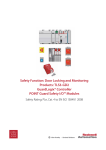
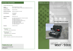
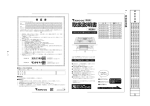
Operations Manual:
Vent Tube
Detection System
REV 1-072214
DORCIA ENGINEERING - VENT TUBE DETECTION SYSTEM OPERATION MANUAL
Copyright Clause
Reprints, even of extracts hereof, are permitted only if the source is quoted and permission has been
granted by Dorcia Engineering. The main components, devices, arrangements, as well as software,
control and instrumentation equipment on all of our Vent Tube Detection Systems are proprietary
and protected both at home and abroad by patent applications, design registrations or copyright.
Table of Contents
2 FORWARD
3 SAFETY & GUARANTEE
3.1 General Safety Instructions
3.2 Uncrating and Inspection
3.3 Choosing the Installation Site
3.4 Safety of Personnel
3.5 Terms of Guarantee
4 SPECIFICATIONS
5 INSTALLATION
5.1 Installation Site Considerations
5.2 Wiring
6 INDICATORS & OPERATOR INTERFACE
6.1 Indicators 6.2 Operator Interface
7 THEORY OF OPERATION & SYSTEM OUTPUTS
7.1 Theory of Operation
7.2 System Outputs
8 MAINTENANCE & SPARE PARTS
8.1 Maintenance
8.2 Spare Parts
9 AFTERWARD
131 SOUTH LOMBARD RD
PHONE 630.632.0955
AN INNOVATIVE
ADDISON, IL 60101
WWW.DORCIAENGINEERING.COM
SOLUTION BY DORCIA
2.0 FORWARD
This service manual is provided to serve as the installation, operation and maintenance guide for
the equipment supplied by Dorcia Engineering. The contents should be read before attempting any
phase of installation, operation and maintenance. The Dorcia Engineering Vent Tube Detection System
(VTDS) requires installation by the customer or prearranged contractor. Unpack carefully and check
all items received against the invoice.
The Dorcia Engineering Vent Tube Detection System has been tested and passed quality-control
inspections in accordance with Dorcia Engineering standard procedures. However, the equipment
as shipped may have been opened or disassembled for inspection, cleaning, etc., after testing. The
customer should confirm that no nuts, bolts, flanges, enclosures or any other component have not
become loose during shipment; these should be tightened wherever necessary.
An identification tag has been permanently attached to the equipment. When requesting information,
service or spare parts, please be prepared to furnish the part number and serial number located on the
identification tag. It is the user’s responsibility to check actual operating conditions to ensure the vent
tube detection system components, materials of construction, and sealing materials are compatible
with the application and are within local safety codes.
Dorcia Engineering reserves the right to modify the contents of this service manual without notification.
131 SOUTH LOMBARD RD
PHONE 630.632.0955
AN INNOVATIVE
ADDISON, IL 60101
WWW.DORCIAENGINEERING.COM
SOLUTION BY DORCIA
3.0 SAFETY & GUARANTEE
3.1 General Safety Instructions
It is important that all personnel in charge of installing, setting-up, operating, maintaining or
repairing the Vent Tube Detection System and its components read and understand this manual.
Care must be taken when referring to this manual to ensure adherence to all warnings, cautions and
important notes. These carry information related to the safety of personnel and the integrity and
satisfactory operation of the equipment.
3.2 Uncrating and Inspection
Prior to uncrating the Vent Tube Detection System, inspect the exterior crating for obvious damage
that may have occurred during shipment. All damage should be reported to both the freight carrier
and Dorcia Engineering. Obtain the full part number and serial number from the identification tag
then contact Dorcia’s Technical Support Department at: [email protected]
While uncrating the VTDS, take care to avoid damaging the wiring of critical electrical and
mechanical components. After removing the VTDS from its crate, carefully inspect the skid for
damage that may not have been obvious during the initial inspection. It is good practice to ensure
all fittings are tight and have not come loose during shipment.
3.3 Choosing the Installation Site
Prior to installing or operating the VTDS, consult your safety manager or plant manager regarding
the possibility of physical damage or electrical interference.
Do not install or operate the VTDS in or near environments that contain large electromagnetic fields.
Contact your local Dorcia Engineering representative for more details.
3.4 Safety of Personnel
Service and maintenance work for the VTDS should only be conducted by trained individuals who
have read the operation manual. Contact your local Dorcia Engineering representative for more
details.
3.5 Terms of Guarantee
The Vent Tube Detection System carries a warranty specified within the terms and conditions of the
original sale (please refer to Dorcia Engineering’s standard terms and conditions for exact details).
Dorcia Engineering is not liable for damage or poor performance resulting from:
• Improper use
• Failure to observe warnings and guidelines in this manual
• Purchase of complimentary/spare parts from parties other than Dorcia Engineering
• Employment of insufficiently qualified personnel
• Unauthorized modifications of the VTDS and its components
In these cases Dorcia Engineering’s warranty/guarantee is rendered void
131 SOUTH LOMBARD RD
PHONE 630.632.0955
AN INNOVATIVE
ADDISON, IL 60101
WWW.DORCIAENGINEERING.COM
SOLUTION BY DORCIA
4 SPECIFICATIONS
Materials of Construction :
VTDS Side Rails Sensor Detection Assembly Enclosures Electrical Connectors Indicators Delrin®
304 Stainless Steel, Nema 4X, IP68
IP 68 rated gold plated contacts
Allen Bradley 800FP Series
5 INSTALLATION
5.1 Installation Site Considerations
Before attempting to install the Vent Tube Detection System consider the following:
• Allow for 36 inches of clearance from all electromagnetic fields on all sides of the Vent Tube
Detection System (VTDS)
• VTDS requires 24VDC supply voltage rated with max current consumption without outputs of
<300mA @ 24VDC and earth ground
• VTDS electronics protected in IP 68 rated enclosure
• Please Review System Dimensions (see Figure 1 below) for proper drill and DO NOT drill mounting
options
• VTDS is designed to be mounted in the ideal orientation (see Figure 2 mounting orientation
below)
Step 1 - Please refer to Figure 1 System Dimensions for proper drill and DO NOT drill areas shown
below. If these areas are drilled into or modified in anyway the Sensor Detection Assembly (SDA)
module will be damaged and the warranty of the system will be voided.
Step 2 -Mount SDA’s directly opposite each other with the side rail surfaces facing each as shown in
ideal mounting orientation (Figure 2)
Step 3 - The SDA’s are designed to replace the existing side rails on the conveyor. If they do not
directly replace the side rails, please contact Dorcia Engineering. DO NOT modify the side rails of the
SDA’s in anyway without written consent from Dorcia Engineering.
Step 4 - Connect the flying leads of each of the SDA cables as shown below in section 5.2
Step 5 - Connect the end of the cable with the pre-attached cord grip and interconnect to the
appropriate user connection on the SDA’s.
Step 6 - Apply the correct voltage power to each SDA module.
131 SOUTH LOMBARD RD
PHONE 630.632.0955
AN INNOVATIVE
ADDISON, IL 60101
WWW.DORCIAENGINEERING.COM
SOLUTION BY DORCIA
Step 7 - Start Up Sequence
When power is initially connected to the unit each VTDS SDA will exhibit the following
start-up sequence:
1. Green light illuminates (this indicates that the correct voltage is supplied to the unit and the unit
is powered.
2. Yellow light will illuminate
3. Red light will illuminate
4. Yellow light will turn off
5. Red light will turn off
6. Both red and yellow light will flash on and then off quickly.
7. Green light should stay illuminated during and after the entire sequence
131 SOUTH LOMBARD RD
PHONE 630.632.0955
AN INNOVATIVE
ADDISON, IL 60101
WWW.DORCIAENGINEERING.COM
SOLUTION BY DORCIA
Figure 1. System Dimensions (inches)
Figure 2. Ideal Mounting orientation
131 SOUTH LOMBARD RD
PHONE 630.632.0955
AN INNOVATIVE
ADDISON, IL 60101
WWW.DORCIAENGINEERING.COM
SOLUTION BY DORCIA
5.2 Wiring
Wiring Color Description
1. Black = (+V) 24 VDC Power
2. Yellow = Zero voltage (0V) 24 VDC Power
3. Blue = Earth GND
4. Orange = Detection (24V Output)
5. Red = Heartbeat (24V Output)
131 SOUTH LOMBARD RD
PHONE 630.632.0955
AN INNOVATIVE
ADDISON, IL 60101
WWW.DORCIAENGINEERING.COM
SOLUTION BY DORCIA
6 INDICATORS & OPERATOR INTERFACE
6.1 Indicators
Each Sensor Detection Assembly (SDA) of the Vent Tube Detection System (VTDS) has local indication
of the overall system power, if service is required, and if a traceable vent tube has been detected.
There are (3) indicating lights on each face of the SDA’s:
Amber = Vent Tube Detected - The amber light will illuminate when a traceable vent tube is located
Green = System Power - The green light will illuminate while there is 24VDC supplied to the VTDS
Red = Service Required- The red light will illuminate or flash when service is required
When the system is supplied power the system will go through a pre-set start up sequence. The green
power light will illuminate, then shortly thereafter the amber light will illuminate and then finally the
red light will illuminate. Upon successful completion of the start up sequence both the amber light
and the red light will blink once and then remain off until their perspective action is required. If for
any reason this sequence is not reproduced during start up please contact Dorcia Engineering for
assistance.
131 SOUTH LOMBARD RD
PHONE 630.632.0955
AN INNOVATIVE
ADDISON, IL 60101
WWW.DORCIAENGINEERING.COM
SOLUTION BY DORCIA
6.2 Operator Interface
The following illustrate the possible visual indicators during normal operation:
Unit is “ON” & Operational
Unit is “OFF”
PULSE
Traceable Vent Tube Detected
Unit is sensing an Error
Contact Dorcia Engineering on the 24/7 service line (630) 632-0955
131 SOUTH LOMBARD RD
PHONE 630.632.0955
AN INNOVATIVE
ADDISON, IL 60101
WWW.DORCIAENGINEERING.COM
SOLUTION BY DORCIA
7 THEORY OF OPERATION & SYSTEM OUTPUTS
7.1 Theory of Operation
The VTDS uses patented state of the art technology to The system consists of two sense the presences
of a traceable vent tube in a can. The standard Dorcia Engineering VTDS provides the filling machine
owner / operator with both visual indications (as discussed above) as well as discrete 24VDC output
signal whenever a vent tube malfunction occurs. The VTDS requires the use of Dorcia Engineering’s
patented Traceable Vent Tubes in order to reliably and accurately sense the presence of a traceable
vent tube.
7.2 System Outputs
When a traceable vent tube moves within the sensing field of the VTDS the operator will receive a
visual indication (see above) as well as a discrete 24VDC output.
Upon detection of a traceable vent tube, the standard VTDS configuration is to transmit a discrete
24VDC signal via the orange output wire (see below).
131 SOUTH LOMBARD RD
PHONE 630.632.0955
AN INNOVATIVE
ADDISON, IL 60101
WWW.DORCIAENGINEERING.COM
SOLUTION BY DORCIA
Wiring Color Description
1. Black = (+V) 24 VDC Power
2. Yellow = Zero voltage (0V) 24 VDC Power
3. Blue = Earth GND
4. Orange = Detection (24V Output)
5. Red = Heartbeat (24V Output)
This configuration can be modified to a “fail safe” condition to where the 24VDC signal is generated
until a traceable vent tube is detected.
The desired user output timing can be configured based on the customer’s specific programming
needs (see below)
output
period
high
low
time
Please contact Dorcia Engineering for your specific ideal programming signal output conditions.
Maintenance The heartbeat function of the VTDS provides the user a continual 24 VDC system health
check. The duty cycle and frequency can be customized to the users specifications.
131 SOUTH LOMBARD RD
PHONE 630.632.0955
AN INNOVATIVE
ADDISON, IL 60101
WWW.DORCIAENGINEERING.COM
SOLUTION BY DORCIA
8 MAINTENANCE & SPARE PARTS
8.1 Maintenance
In order to give the owner / operator a real time indication of the VTDS system health, the standard
VTDS comes with a constant electrical pulse heart beat signal as well as a locally mounted indicator
light. Each Sensor Detection Assembly (SDA) performs its own system health check and informs the
operator that the individual SDA the are functioning properly.
In the event that an error within the system occurs, the self-diagnostic software will cause the RED
indicator to illuminate. Additionally ,if there is a complete system failure the heartbeat function will
transmit an alarm signal via the 24VDC discrete heartbeat signal on the RED wire.
8.2 Spare parts
For any spare parts please contact your Dorcia Engineering’s manufacture representative or Technical
Support Department at 5 or email: [email protected]
9.0 AFTERWARD
The purpose of Dorica Engineering is to help our customers and the companies we work with to be
the best they can be. We appreciate the opportunity to serve you and your organization.
For any additional information please contact Dorica Engineering or visit our website
www.DorciaEngineering.com
Specifications and information herein are subject to change without notice.
©Dorcia, LLC 2014. All Rights Reserved // REV 1-072214
131 SOUTH LOMBARD RD
PHONE 630.632.0955
AN INNOVATIVE
ADDISON, IL 60101
WWW.DORCIAENGINEERING.COM
SOLUTION BY DORCIA