Download TECHNICAL
Transcript
MAY 2013
TECHNICAL
E-RESOURCES
IN THIS ISSUE
• Did You Know
• Compressor Testing
• Mingledorff’s Class
Schedule
DID YOU KNOW?
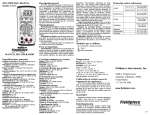
Mingledorff’s has Meter’s in stock to properly diagnose compressor windings.
Such as the Fieldpiece LT17A meter measures
current, resistance, voltage, capacitance,
frequency, continuity, and temperature. Test
leads store in the meter body and, with the probe
tips removed, connect the LT17A to Fieldpiece
accessory heads. The body is made out of durable
ABS plastic and comes with a bright blue backlight
for poorly lit test areas. Get great accuracy using
the included k-type thermocouple and an easily
accessible temperature calibration pot.
IDENTIFYING UNMARKED TERMINALS OF A PSC/CSR MOTOR
Link to Mingledorff’s Web page
www.mingledorffs.com
Link to HVACpartners Web page
www.hvacpartners.com
Link to Totaline Newsletter
www.totaline.com/newsletter
Link to Carrier Home Web page
www.carrier.com
Link to Bryant Home Web page
www.bryant.com
Link to Payne Home Page
www.payne.com
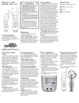
Sometimes the terminals on a single-phase compressor are not marked or are
hard to identify. The terminals can be identified using a VOM/DMM to measure
the resistance of the motor windings. The procedure is provided in the detailed
procedure at the end of this section and briefly described below.
First, use the VOM/DMM to find the two terminals across which the highest resistance
is measured. These are the run (R) and start (S) terminals. The remaining terminal is
the common (C) terminal. Next, put one lead of the VOM/DMM on the common
(C) terminal, then put the other lead on one of the other two remaining terminals
to find the highest resistance. This is the start winding (S) terminal. The remaining
terminal is the run winding (R) terminal. This example is for single phase compressors,
for three phase compressors will have equal ohm reading i.e. T1-T2= 5 ohm, T1-T3 =
5 ohms, T2-T3 = 5 ohms.
TECHNICAL
MAY 2013
E-RESOURCES
SAFETY PRECAUTIONS
When making electrical measurements and/or repairs on equipment, always follow the precautions listed below.
• Read and follow all safety instructions given in the manufacturer’s installation instructions and/or service manual for
the specific system being serviced.
• Always turn off the main power to a system before making any repairs. There may be more than one disconnect
switch. If applicable, turn off the accessory power. Tag and lock out all disconnect switches.
• Always remove rings, watches, and other jewelry to lessen the chance of electrical shock.
• When making voltage, current, or continuity measurements on a hermetic or semi-hermetic compressor in a
pressurized system, do not place the meter probes directly on the compressor terminals. If the compressor terminals
are damaged and the system is pressurized, disturbing them to take measurements could cause them to blow out,
causing injury. Once the charge has been removed and the system is no longer under pressure, measurements can
be made at the compressor terminals.
• Do not override or bypass safety controls such as electrical interlocks, unless directed by the manufacturer’s service
literature.
• When troubleshooting a start relay circuit, remember that the back EMF generated by a motor can be much higher
than the line voltage applied to the motor. For example, a motor powered by 230 volts can generate back EMF
voltages greater than 400 volts.
• Never replace a blown fuse without correcting the cause of the original failure. If thermally operated circuit breakers
or overloads are tripping, make sure the trip is not due to excessively high ambient temperatures or loose
connections. Also, make sure that HACR-rated circuit breakers are being used.
• Do not allow fluid from a ruptured run capacitor to contact your skin or clothing. Older capacitors may contain PCBs
(polychlorinated biphenyls). These capacitors must be treated as hazardous waste and be disposed of in
accordance with applicable local or national codes.
TECHINICAL E-RESOURCES
TECHNICAL
MAY 2013
E-RESOURCES
BASIC HEAT PUMP OPERATION AND
ELECTRICAL TROUBLESHOOTING
ONE FULL DAY
(8:00 a.m. - 4:30 p.m.) $175 each
Course qualifies for (8) C.E.U. credit hours. For Georgia, Alabama & N.A.T.E.
**Student must provide NATE ID number and
photo ID to receive NATE CEU credits**
MAY 22, 2013
Norcross Training Room
CLASS INCLUDES:
Power point presentation & discussion of basic heat pump refrigeration circuit, electrical ladder
diagrams, control circuit operation, charging with superheat and subcooling method, long line
applications, low ambient operation, basic air flow measurements, burnout procedures, system
dehydration procedure and proper brazing procedure with nitrogen purge.Students will custom wire
and troubleshoot an actual heat-pump demonstrator board.
FOR REGISTRATION FORM, OR INFORMATION, PLEASE CONTACT:
June Norman in Norcross, Ga.
Ph: 770-239-2134 Fax: 770-239-2137 [email protected]
Donna Hutchins in Savannah, Ga.
Ph: 912-236-8122 Fax: 912-232-1924 [email protected]
Debbie Lanier in Macon, Ga.
Ph: 478-477-3193 Fax:478-474-3987 [email protected]
TECHNICAL E-RESOURCES


