1
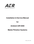
w w w. p u r a f i l . c o m
FIRST
CL E A N
AIR
IN
SERVICE
G U I D EFor
ELECTRONIC
CABINET UNIT
I N S TA L L AT I O N , O P E R AT I O N & M A I N T E N A N C E
INSTRUCTIONS
TO BE USED IN CONJUNCTION WITH:
SERVICE GUIDE for Gage Unit
SERVICE GUIDE for Blower Assembly
Purafil, Inc. • 2654 Weaver Way, Doraville, Georgia, 30340, U.S.A. • www.purafil.com • tel: (770) 662-8545 • (800) 222-6367
© Purafil 2012 SrvcGde - ECU - 01
ISO 9001:2008
TABLE OF CONTENTS
1.0 PRE-INSTALLATION INSTRUCTIONS
1.1 SAFETY CONSIDERATIONS
1.2 RECEIVING INSTRUCTIONS
1.3 INSEPECTION
1.4 CLEARANCES
2.0 OPERATIONAL CONCEPTS AND DETAILS
2.1 ECU APPLICATIONS
2.2 HOW PURAFIL SYSTEMS WORK
2.3 BASIC DESIGN OF THE ECU
3.0 INSTALLATION
3.1 POSITIONING THE UNIT
3.2 MODULES
3.3 PARTICULATE FILTERS
3.4 POST-START INSEPECTION/CHECK
4.0 MAINTENANCE
4.1 REPLACEMENT PARTS AND MATERIALS
4.2 SPECIAL PRECAUTIONS
4.3 PURAFIL STAIN REMOVAL
5.0 WIRING DIAGRAMS
6.0 TROUBLESHOOTING
7.0 WARRANTY INFORMATION
8.0 SAMPLING RECORD
LIST OF FIGURES
FIGURE
TITLE
1
BASIC DESIGN OF THE ECU
2
ECU WIRING
1.0 PRE-INSTALLATION INSTRUCTIONS
1.1 SAFETY CONSIDERATIONS
-
Read this Service Manual carefully. Be thoroughly familiar with the
controls and the proper use of the equipment.
-
This manual should be retained with the unit because it contains the
information necessary for proper maintenance. Keep it with the unit.
-
Keep all nuts, bolts, and screws tight to be sure the equipment is in
safe working condition.
CAUTION:
-
Installer should be a trained, experienced service person.
-
Disconnect power supply before wiring connections are made to
prevent possible electric shock or damage to equipment.
-
Never pressurize the equipment in excess of specified test pressure.
-
Never enter an enclosed blower cabinet or reach into a unit while the
fan is running.
-
Always conduct a thorough check out when the installation is
complete.
1.2 RECEIVING INSTRUCTIONS
Systems are normally shipped assembled and with motor mounted.
The units are well protected with triple-wall cardboard and secured
with shipping bands.
Upon receiving systems from Purafil, Inc., note any shipping damage,
obvious or hidden, to your carrier and on your Bill of Lading. All
problems should be handled between the customer and carrier except
for U.P.S. shipments, which require the customer to contact Purafil,
Inc. for action.
To unpack unit, cut shipping bands and remove packaging. See
installation instructions for complete directions on how to mount the
unit.
1.3 INSPECTION
The condition of the unit upon its arrival is critical to its proper operation.
Prior to start-up, inspect the unit carefully, according to the checklist
below. Correct any inadequacies before start-up to prevent possible
damage or inefficiency. Note, should there be any questions concerning
the unit and refer to the numbers found on the unit identification plate,
when contacting the Purafil representative.
PRE-OPERATION CHECK LIST
YES
NO
CONDITION
____
1. Configuration and material are as specified on the sales
order form
____
____
2. Measurements fit submittal requirements
____
____
3. Parts are all present including modules, particulate filters,
media, and gage units
____
____
4. Motor phase and voltage are correct
____
____
5. Modules, prefilter, and final filter all fit properly
____
____
6. Latches hold securely and gaskets seal properly
____
____
7. Labels and serial numbers are present
____
____
8. Airflow direction is consistent with installation requirements
(check labels attached to unit)
____
Note, checking specific points is also imperative after the unit is started
up. See section 3.4 in this manual for checklist.
1.4 CLEARANCE
All units should be easily accessible for the required periodic
maintenance. The local Purafil representative can recommend sufficient
minimum clearances.
2.0 OPERATIONAL CONCEPTS AND DETAILS
2.1 ECU APPLICATIONS
Industry is finding varied methods for applying electronics to the process
control aspect of manufacturing. This technology has lead to the use of
freestanding controllers that are located randomly throughout the
manufacturing works, instead of being enclosed in a control room. The
need for protecting this equipment from corrosive gases is just as critical
as major computer or control centers. The Purafil Electronic Cabinet Unit
was developed to serve this area of computer protection. The ECU can be
mounted directly on a sealed computer room to create a microclimate
inside the room to provide maximum security for delicate and expensive
equipment.
2.2 HOW PURAFIL SYSTEMS WORK
The ECU is a recalculating unit designed to be mounted on a sealed
computer room that requires gas phase filtration. The ECU will create a
microclimate inside the room, which will protect valuable electronic
equipment.
2.3 BASIC DESIGN OF THE ECU
The ECU houses a three-fold method of air purification. Powered by an
Inline direct drive plastic blower and a 115-volt, single-phase, 60-hertz,
open motor.
(NOTE: The ECU can accommodate different electrical requirements, but
these requirements must be specified prior to ordering the unit).
The ECU channels air through a 30% efficiency PP-30 particulate filter
which prevents atmospheric dust from clogging the pores of the purafil
media and protects the surface of the Purafil MediaPAKTM PK-12 Module
assembly which contains the media. Next the air moves through the PK12 Module which is filled with Purafil media for gaseous contaminate
removal. Before exiting the unit the air moves through a high efficiency
box-type, final filter. (See Figure 1)
The ECU is constructed of Cold Rolled Steel and painted with a textured
Grey polyurethane paint.
FIGURE 1: BASIC DESIGN OF THE ECU
The ECU includes the following sequential components:
1. Damper – The air control damper allows the operator to regulate the
amount of recirculated air that passes through the unit.
2. Prefilter – As the air enters the unit it passes through 30-35%
efficiency PP-30 particulate filter. The prefilter collects atmospheric
dust and larger particles, thereby preventing clogging of the
perforated surfaces and pellet pores in the next stage of the unit.
3. PK-12 Module Section – The air passes through perforated, “V”
shaped PK-12 Modules, which contains the user’s choice of Purafil
media dependent upon the atmosphere to be controlled.
4. Final Filter – Before exiting the unit the air moves through a high
efficiency box-type, final filter any remaining contaminants such as
media dust and airborne contaminants are removed in this stage.
5. Blower – The air is propelled through the unit using a direct drive
Inline blower that is constructed of plastic and powered by a 115-volt
open motor.
6. Gages – The Minihelic gage indicates if the ECU is providing proper
cabinet pressurization.
3.0 INSTALLATION
After the entire pre-operative inspection is finished (Section 1.3),
complete the following sequence for installation by referring to the
instructions in Section 3.1 – 3.4 below:
1. Remove the unit from the skid and position it in the designated operation
location.
2. Hook up the electrical connections and check for proper rotation.
3. Install the Modules. (See Section 3.2)
4. Install the particulate filters. (See Section 3.3)
5. Start the unit (see Section 3.4).
6. Perform post-start inspection check. (See Section 3.4)
3.1 POSITIONING THE UNIT
The standard unit can simply be lifted from its skid and “walked” or
transported by lift to its pre-designated operation location (if in close
proximity to the skid), according to facility safety requirements. The ECU
is designed to sit on the ground or it can be hung directly onto the
cabinet using the holes located on the back of the unit (See Fig 1)
3.2 MODULES
Proper installation and maintenance of the chemical filtration media is
critical to the units efficient operation. The modules are designed
specifically for media manufactured by Purafil, Inc. and allow the media
to perform to its maximum efficiency, through proper shape and bed
depth. When installing the module the point of the “V” must be facing
upward. Unit will be labeled showing proper module configuration.
3.3 PARTICULATE FILTERS
Proper selection and installation of particulate filters for use in Purafil
Systems are necessary steps in obtaining the air quality best suited to the
user’s needs. Particulate filters are available in different sizes and
efficiencies, and variations in either of these characteristics may affect the
efficiency of the Purafil system. To install the particulate filters slide it
along the track provided.
3.4 POST-START INSPECTION/CHECK
Before initial start-up of system, contact your local PURAFIL® representative.
Their name and phone number is attached to your system.
YES
NO
CONDITION
____
____
1. Fan rotation is in the proper direction. (See
Figure 7)
____
____
2. Joints, seals, and gaskets do not leak.
____
____
3. Gages work properly (i.e.lines hooked up
correctly).
____
____
4. Dampers work properly
____
____
5. Modules are completely full of media and fit
properly.
____
____
6. After 1-2 weeks of operation check belt(s) and
tighten if necessary. (See Blower Assembly
Service Guide)
4.0 MAINTENANCE
4.1 REPLACEMENT PARTS AND MATERIALS
While Purafil, Inc. products are built with durability, some parts of the
Purafil unit will require replacement during the normal lifetime of the
equipment. Replacement items may be ordered from your local Purafil
representative or from Purafil, Inc. Certain moving parts such as motors,
bearings and belts may be obtained from conventional local sources.
Consumables
In order to maintain proper performance levels, particulate filters and
Purafil media must be replaced periodically, as they have a finite life (See
Media Sampling Procedure Service Guide)
4.2 SPECIAL PRECAUTIONS
Disposal
Purafil media is a non-toxic, non-flammable substance. Filtration of
contaminants through Purafil media causes molecular changes to occur,
and the resulting product is usually not harmful to the environment.
Although special precautions are generally not required when disposing
of spent media, government regulations may require specific disposal
procedures if the resulting product could be harmful to the environment.
Independent laboratory analysis for Environmental Protection Agency
toxicity characteristics may be required if the contaminants eliminated
from your environment include heavy metals and pesticides.
Inhalation
Workers should avoid direct inhalation of considerable Purafil dust, as it
induces sneezing. In closed, unventilated spaces, dust masks such as the
3-M No. 8500 are suggested.
Eye Contact
If dust is exposed to the eyes or delicate membrane, flush thoroughly
with water and seek treatment by a physician. Follow normal procedures
for exposure to abrasive dust.
Water
Avoid exposing the Purafil media to water or precipitation, as this
dissolves permanganate content. Storage of the media should be in a dry
place with less than 95% relative humidity. Exposure of permanganate
solution to the skin causes brown staining which is temporary and not
harmful. This staining can be removed by washing in a diluted solution of
water and sodium bisulfate.
4.2 PURAFIL STAIN REMOVAL
The following stain removal procedure is stated here as information only,
and neither Purafil, Inc. nor its subsidiaries, nor any agent or employee of
Purafil, Inc. makes any warranty or other representation regarding the
efficiency or safety of this procedure. The stain removal could cause
further damage to the garment or to the item from which one may
attempt to remove the stain.
Note: Sodium bisulfate gives off sulfur dioxide gas; therefore; it must be
used in a well-ventilated area.
5.0 WIRING DIAGRAMS
The ECU will be pre-wired before leaving Purafil, Inc. Wires may vibrate
loose with rough handling. Check all wiring connections before start-up.
If any problems occur contact your local Purafil representative
immediately. (See Figure 2) if there are any questions.
NOTE: A PROFESSIONAL ELECTRICIAN SHOULD PERFORM ALL WIRING
REPAIRS.
FIGURE 2: ECU WIRING
6.0 TROUBLESHOOTING
SYMPTOM
PROBLEM
Dust blowing out discharge Final filter not in place
opening
Unit fails to operate
Airflow too low
CHECKS/REMEDY
Insert appropriate final filter
Final filter heavily soiled
Change the appropriate final
filter
No voltage
Check power source
Improper voltage
Verify voltage from power
source
Defective motor
Replace
Motor improperly wired
Rewire
Blown fuse or open circuit Replace fuse or reset
breaker
Filters may be loaded
Change filters
PK-12 Module perforated Vacuum or blow off with
surface may be clogged
compressed air
7.0 WARRANTY
Purafil warrants hardware equipment manufactured by Purafil to be free
from defects in material and workmanship under normal use and service for
one (1) year from shipment date. Purafil’s obligation under this warranty
shall be limited to replacing any parts thereof, which shall be demonstrated
to have been defective. THIS WARRANTY EXPRESSLY IN LIEU OF ALL OTHER
WARRANTIES, EXPRESS OR IMPLIED, INCLUDING THE WARRANTIES OF
MERCHANTABILITY AND FITNESS.
PURAFIL MAKES NO WARRANTIES AS TO MERCHANTABILITY OR AS TO THE
FITNESS OF THE MERCHANDISE FOR ANY PARTICULAR USE AND SHALL NOT
BE LIABLE FOR ANY LOSS OR DAMAGE, DIRECTLY OR INDIRECTLY, ARISING
FROM THE USE OF SUCH MERCHANDISE OR FOR CONSEQUENTIAL
DAMAGES. No person, firm or corporation is authorized to assume for
Purafil any other liability in connection with the sale of these goods.
Equipment, parts and material manufactured by others and incorporated in
Purafil equipment are warranted by PURAFIL ONLY TO THE EXTENT OF THE
ORIGINAL MANUFACTURERS LIABILITY TO PURAFIL.
8.0 SAMPLE RECORD
Sampling Record / Schedule
Represented By:
Important Notice
The information contained in this Bulletin reflects the results of various testing and
analytical procedures believed by PURAFIL, INC. (a U.S.A. corporation) to be useful
indicators of the relative performance of air filtration systems and media. It is
intended for use by persons having appropriate scientific and technical knowledge
and experience at their own risk. This bulletin does not in any way constitute a
representation, warranty, promise, or guarantee by PURAFIL, INC. of the installed
performance of PURAFIL® media.