1
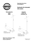
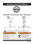
Operating Instructions & Parts Manual
Hydraulic Telescopic Transmission Jacks
Model Number
42001 (Air/ Manual)
42003 (Manual)
Model No. 42001
Capacity
1 Ton
1 Ton
Model No. 42003
SFA Companies ©2006
http://www.omegalift.com
Read this manual and follow all the Safety Rules and Operating Instructions before using this product.
Printed in Taiwan
42001-M0 rev 08/06
ONE YEAR LIMITED WARRANTY
For a period of one (1) year from date of purchase, SFA Companies will repair or replace, at its option, without
charge, any of its products which fails due to a defect in material or workmanship under normal usage. This limited
warranty is a consumer's exclusive remedy.
Performance of any obligation under this warranty may be obtained by returning the warranted product, freight
prepaid, to SFA Companies Warranty Service Department, 10939 N. Pomona Ave., Kansas City, MO 64153.
Except where such limitations and exclusions are specifically prohibited by applicable law, (1) THE CONSUMER'S
SOLE AND EXCLUSIVE REMEDY SHALL BE THE REPAIR OR REPLACEMENT OF DEFECTIVE PRODUCTS AS
DESCRIBED ABOVE. (2) SFA Companies SHALL NOT BE LIABLE FOR ANY CONSEQUENTIAL OR INCIDENTAL
DAMAGE OR LOSS WHATSOEVER. (3) ANY IMPLIED WARRANTIES, INCLUDING WITHOUT LIMITATION THE
IMPLIED WARRANTIES OF MERCHANTABILITY AND FITNESS FOR A PARTICULAR PURPOSE, SHALL BE LIMITED
TO ONE YEAR, OTHERWISE THE REPAIR, REPLACEMENT OR REFUND AS PROVIDED UNDER THIS EXPRESS
LIMITED WARRANTY IS THE EXCLUSIVE REMEDY OF THE CONSUMER, AND IS PROVIDED IN LIEU OF ALL
OTHER WARRANTIES, EXPRESS OR IMPLIED. (4) ANY MODIFICATION, ALTERATION, ABUSE, UNAUTHORIZED
SERVICE OR ORNAMENTAL DESIGN VOIDS THIS WARRANTY AND IS NOT COVERED BY THIS WARRANTY.
Some states do not allow limitations on how long an implied warranty lasts, so the above limitation may not
apply to you. Some states do not allow the exclusion or limitation of incidental or consequential damages, so the above
limitation or exclusion may not apply to you. This warranty gives you specific legal rights, and you may also have other
rights which vary from state to state.
SFA Companies ©2005
10939 N. Pomona Ave. Kansas City, MO 64153
888-332-6419
[email protected]
2
Save these instructions. For your safety, read, understand, and follow the information provided with and on this jack.
The owner and operator of this equipment shall have an understanding of this jack and safe operating procedures before
attempting to use. The owner and operator shall be aware that use and repair of this product may require special skills
and knowledge. Instructions and safety information shall be conveyed in the operator's native language before use of
this jack is authorized. If any doubt exists as to the safe and proper use of this jack, remove from service immediately.
Inspect before each use. Do not use if broken, bent, cracked or damaged parts are noted. Any jack that appears
damaged in any way, or operates abnormally shall be removed from service immediately. If the jack has been or
suspected to have been subjected to a shock load (a load dropped suddenly, unexpectedly upon it), immediately
discontinue use until jack has been checked by an Omega authorized service center. It is recommended that an annual
inspection be done by qualified personnel and that any missing or damaged parts, decals, warning/safety label or signs
be replaced with Omega replacements parts only. Labels and Operator's Manuals are available from manufacturer (see
Replacement Parts, pages 6 & 7).
PRODUCT DESCRIPTION
Omega Hydraulic Telescopic Transmission Jacks are designed to be used as an aid in the removal and installation of
automotive and light truck transmissions, transfer cases and transaxles. They are intended for use under an overhead
lift or in a garage pit. The air actuated function is an added feature on Model 42001. For Model 42001, ensure that your
air source can dedicate 7.8 CFM @ 90 - 175 PSI. To ensure dependable, trouble free operation an inline air dryer and
oiler is recommended.
SPECIFICATIONS
Model
Capacity
Min.
Height
Max.
Height
Min. Saddle Area
Max. Saddle Area
Base Size
42001
2000 lb.
48 5/8
77 3/8
15 1/2" x 12 5/8"
24 1/2" x 18 7/8"
42 1/8" x 39 1/2"
42003
2000 lb.
48 5/8
77 3/8
15 1/2" x 12 5/8"
24 1/2" x 18 7/8"
42 1/8" x 39 1/2"
CAUTION: READ CAREFULLY BEFORE UNPACKING PRODUCT.
Saddle
Assembly
Saddle
Assembly
Oil Filler Screw
(not shown)
Position Handle
Chain
Bracket
Air Supply Inlet
(not shown)
Reservoir
Support Bar
Air Pump Pedal
Lift Pedal
Oil Filler Screw
(not shown)
Tilt Adjustment
Knobs
Position Handle
Tilt Adjustment
Knobs
Chain
Bracket
Reservoir
Lift pedal
Air Pump
Support Bar
Release Valve
Release Valve
Base Halves
Base Halves
Swivel Caster
Swivel Caster
Figure 1 - Model 42001 Nomenclature
Figure 2 - Model 42003 Nomenclature
Note: Vent Screw and Oil Filler Screw are located on the upper portion of the reservoir.
3
ASSEMBLY
BEFORE USE
Refer to Figure 1 & 2:
1. Three major parts should be included in package:
(a) Hydraulic unit with pumping mechanism ( with
air motor equipped for model 42001),
(b) saddle unit, and
(c) 2 pieces of base half with bolts and washers.
2. Attach one of the base halves to the base of the
hydraulic unit, then secure using allen head bolts and
washers provided. Then apply the same procedure to
the other base half. Use torque wrench to tighten to
30 lb. ft. Do not overtighten.
3. Attach the brackets to reservoir, then attach one end
of the suppor bar to base half and the other end to the
bracket. Secure with bolts and nuts provided. Repeat
for all other three support bars.
4. Slide the position handle to reservoir from top, then
secure with bolts and nuts provided.
5. Move the saddle unit above the ram piston, place the
saddle socket onto the ram piston. Secure using the
set screw.
1. Inspect jack before each use. Do not use if bent,
broken or cracked components are noted. Ensure that
casters move freely. Check for and tighten any loose
assemblies.
2. Verify that the product and the application are
compatible, if in doubt call Omega Technical
Service (888)332-6419
3. With saddle fully lowered, remove shipping screw and
replace with vent screw. (shipping screw is located
on top of the oil filler screw)
4. Ensure oil level is just below the rim of the oil filler
screw hole. Reinstall the oil filler screw.
For Model 42001 only
1. Pour a teaspoon of good quality air tool lubricant into
the air supply inlet (See figure 1). Connect to air supply
and operate for 3 seconds to evenly distribute lubricant.
2. Air actuated product is fitted to accept the popular
1/4" NPT air nipple. When installing air nipple, ensure
thread sealing compound is used on connections. Do
not to allow compound enter the air supply inlet orifice.
Application of thread tape is acceptable, but ensure
that it is not applied beyond the first machine thread.
! WARNING
• Study, understand, and follow all printed materials
provided with/on this product before use.
• Do not exceed rated capacity.
• Use only on hard, level surfaces capable of
supporting rated capacity loads.
• Use of this jack is limited to the removal,
installation and transportation of transmissions,
transfer cases and transaxles. Do not use a
transmission jack to tilt or support a vehicle.
• Ensure the center gravity of load is centered on
the saddle.
• Do not exceed 100 tilt angle of the saddle
assembly in all directions.
• Adequately support the vehicle before starting
repairs.
• Use only chains and slings provided.
• If loaded jack must be moved, make sure that the
load is secured, stable and in lowest position.
• This is a lifting and lowering device only.
• Transfer load immediately to appropriate support
device for service or repair.
• No alterations shall be made to this product
• Failure to heed these markings may result in
personal injury and/or property damage.
OPERATION
Raise saddle:
Caution! For model 42001, do not operate the jack by
pumping the lift pedal and pressing the air pump pedal
at the same time.
1. Pump foot pedal or press air pump pedal until
saddle reaches desired position.
2. Follow vehicle manufacturers recommended
procedures for removing the load as outlined in vehicle
service manual or repair guide.
3. Secure load with provided chains.
4. Ensure load's center of gravity is centered on the
saddle and load is stable before moving jack.
Lower saddle:
Caution! Be sure all tools and personnel are clear before
lowering load.
Slowly, gently apply downward pressure to the release
valve pedal.
! WARNING
To avoid crushing and related
injuries:
NEVER work on, under or
around a load supported only
by a jack. Immediately
transfer the load to an
appropriate work station.
4
MAINTENANCE
Lubrication
1. A periodic coating of light lubricating oil to pivot points,
axles and hinges will help to prevent rust and assure
that wheels, casters and pump assemblies move
freely.
2. When used on a daily basis, air pump model should
be internally lubricated before each use. Use only
good quality air tool lubricant. If no inline oiler is used,
pour a teaspoon of air tool oil into the inlet of the air
supply inlet. Simply operate the jack using the air
feature in order to fully distribute the oil.
Important: Use only a good grade hydraulic jack oil. Avoid
mixing different types of fluid and NEVER use brake fluid,
turbine oil, transmission fluid, motor oil or glycerin.
Improper fluid can cause premature failure of the jack
and the potential for sudden and immediate loss of load.
We recommend Mobil DTE 13M or equivalent.
On air actuated model, periodically check for leaks at
air connections. Replace connections as needed.
Adding oil
1. With saddle fully lowered, set jack in its upright, level
position. Remove oil filler screw.
2. Fill until oil is level with the filler screw hole, reinstall
oil filler screw.
Cleaning
Periodically check the ram for signs of rust or corrosion.
Clean as needed and wipe with an oily cloth.
Note: Never use sandpaper or abrasive material on
these surfaces !
Changing oil
For best performance and longest life, replace the
complete fluid supply at least once a year.
1. With saddle fully lowered, set jack in its upright, level
position. Remove the oil filler screw.
2. Lay the jack on its side and drain the fluid into a
suitable container.
Storage
When not in use, store the jack with saddle in lowest
position and air supply disconnected.
REPLACEMENT PARTS
Note: Dispose of hydraulic fluid in accordance with local
regulations.
Not all components of the jack are replacement items,
but are illustrated as a convenient reference of location
and position in the assembly sequence. When ordering
parts, please give the Model number, part number and
parts description on page 6 & 7. Call or write for current
pricing: SFA Companies 10939 N. Pomona Ave. Kansas
City, MO 64153, U.S.A. Tel:(888)332-6419
Fax:(816)891-6599 E-Mail:[email protected]
Omega Website:http://www.omegalift.com
3. Set jack in its level, upright positon and fill with oil
until just below the rim of the oil filler hole.
4. Reinstall the oil filler screw.
TROUBLESHOOTING
Symptom
Possible Causes
Corrective Action
Jack will not lift load
• Air supply inadequate
(Model 42001 only)
• Hydraulic unit malfunction
• Ensure adequate air supply (Model
42001 ony)
• Contact Omega Tech. Service
Jack bleeds off after lift
• Overload condition
• Hydraulic unit malfunction
• Remedy overload condition
• Contact Omega Tech. Service
Jack will not lower after unloading
• Reservoir overfilled
• Linkage binding
• Drain fluid to proper level
• Clean and lubricate moving parts
Poor lift performance
• Fluid level low
• Ensure proper fluid level
Will not lift to full extension
• Fluid level low
• Ensure proper fluid level
5
Model 42001
Item
1
2
3
4
5
6
7
8
9
10
11
12
13
14
15
16
17
18
19
20
21
-
Part#
324-4-1900-208
G37-3-1320-109
G37-3-1806-105
G36-3-1900-100
G36-6-1809-102
A24-6-8101-107
G36-6-2302-103
G36-6-2300-109
G36-3-2000-109
G37-6-1319-102
G37-3-3300-103
651-1-0127-100
G37-4-5200-105
G37-4-5201-107
G36-3-2300-101
G36-3-2301-103
G37-3-4200-104
G52-4-4102-101
G37-3-2903-209
G37-3-2902-207
G37-3-2901-205
G37-3-9901-109
42001-L0
42001-M0
Description
Screw Assembly
Bracket
Handle
Lift Pedal
Release Valve/ Air Pump Pedal
Male Coupler
Hose Connector
Air Hose
Air Motor
Support Bar
Base Half
Bolt
Caster w/o Brake
Caster w/ Brake
Tilt Screw Assembly
Tilt Screw Assembly
Saddle Plate
Chain & Hook
Saddle Support Bar
Saddle Adjustable Bracket
Saddle Support Seat
Repair Kit for Hydraulic Unit
Product Label
Manual
21
18
3
1
2
Qty
2
2
1
1
2
1
2
1
1
4
2
4
2
2
1
1
1
2
4
2
1
-
20
19
17
5
9
6
7
8
5
4
15
10
12
13, 14
11
Figure 3 - Replacement Parts Illustration for Model 42001
6
8
16
Model 42003
Item
1
2
3
4
5
6
7
8
9
10
11
12
13
14
15
16
17
-
Part#
324-4-1900-208
G37-3-1320-109
G37-3-1806-105
G36-3-1900-100
G36-6-1809-102
G37-6-1319-102
G37-3-3300-103
651-1-0127-100
G37-4-5200-105
G37-4-5201-107
G36-3-2300-101
G36-3-2301-103
G37-3-4200-104
G52-4-4102-101
G37-3-2903-209
G37-3-2902-207
G37-3-2901-205
G37-3-9901-109
42003-L0
42001-M0
Description
Screw Assembly
Bracket
Handle
Lift Pedal
Release Valve Pedal
Support Bar
Base Half
Bolt
Caster w/o Brake
Caster w/ Brake
Tilt Screw Assembly
Tilt Screw Assembly
Saddle Plate
Chain & Hook
Saddle Support Bar
Saddle Adjustable Bracket
Saddle Support Seat
Repair Kit for Hydraulic Unit
Product Label
Manual
Qty
2
2
1
1
1
4
2
4
2
2
1
1
1
2
4
2
1
-
14
15
3
1
16
17
2
13
5
4
11
8
6
9, 10
7
Figure 4 - Replacement Parts Illustration for Model 42003
7
12
Note Page
Contact:
SFA Companies
10939 N. Pomona Ave. Kansas City, MO 64153, U.S.A.
Tel:(888)332-6419 Fax:(816)891-6599
E-Mail:[email protected]
Omega Website: http://www.omegalift.com
8