1
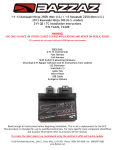
2011-2013 Kawasaki Ninja 250R / 2013 Kawasaki Ninja 300
Z-Fi Installation Instructions
P/N F442
WARNING!
USE ONLY IN RACE OR OTHER CLOSED COURSE APPLICATIONS AND NEVER ON PUBLIC ROADS
Z-Fi products do not meet California CARB highway requirements
Parts List:
Z-Fi Control Unit
Fuel Harness
Download Z-Fi Mapper Software and its Instructions from website
O2 Eliminator
Scotchlok (1)
Cable Ties
Velcro Patch
USB Cable
Swingarm Stickers
Read through all instructions before beginning installation. This is not a replacement for the ECU.
This document is intended for use by qualified technicians. For more specific stock component identifition
and location information refer to a factory service manual.
To create the ideal map(s) we recommend using the optimal Z-AFM self-tuning module
15330 Fairfield Ranch Rd., Unit E, Chino Hills, CA 91709 Phone (909) 597-8300 Fax (909)597-5580
www.Bazzaz.net
BAZZAZ HARNESS CONNECTOR IDENTIFICATION
+12V Switched power
CKPS
Main
TPS
Ground
Z-AFM
Map select
Inj 2 right side
Inj 1 left side
Neutral
Speed sensor
FUEL HARNESS
WE STRONGLY SUGGEST THAT AN EXPERIENCED TECHNICIAN
INSTALL THIS BAZZAZ PRODUCT
1. Begin the installation by removing the seats, left and right side fairing and the fuel tank; now access
the air box and remove it.
2. Place the control unit in the tail of the motorcycle and secure it using the supplied velcro patch. Connect the main connector of the Bazzaz fuel harness into the control unit and begin routing the fuel harness down the left side of the bike.
3. Locate the factory tail light connectors in the tail section of the bike and disconnect them. Connect
the +12V switched power connectors of the Bazzaz fuel harness inline with
the factory connectors.
factory tail light
connectors
Bazzaz +12V switched
power connectors
4. Locate the factory speed sensor connectors on the left side of the bike just before the main frame rail
and disconnect them. Connect the Bazzaz speed sensor connector’s inline with the factory connectors.
Bazzaz speed sensor
connectors
factory speed sensor
connectors
5. Locate the factory injector connectors and route the section of the fuel harness with the injector connectors towards them. Unplug the factory connectors and plug the Bazzaz connectors inline with them
according to the labels. Left will go to injector #1, Right will go to injector #2.
Injector 1
factory injector
connector
Bazzaz injector
connectors
Injector 2
Bazzaz injector
connectors
6. In the same area of the bike, locate the factory neutral sensor lead and
cut the sheathing back about 20mm to expose the green wire. Crimp the
supplied scotchlok onto the green wire and connect the Bazzaz neutral
connector (red connector with white/blue wire) to the scotchlok.
Drive sprocket cover will need
to be removed to gain access.
Bazzaz neutral
connector
Scotchlok crimped onto
exposed factory green wire
factory injector
connector
DISREGARD THE FOLLOWING STEP IF YOUR BIKE DOES NOT HAVE AN O2 SENSOR
7. Locate the factory o2 sensor connector found on the right side of the bike and disconnect. This sensor will no longer be used; the wires should be neatly secured away from any moving components, or the
sensor may be removed and the remaining port/bung in the exhaust can then be plugged. The supplied
O2 eliminator must be connected in place of the O2 sensor connector to avoid triggering a fault code (FI
light). Connect the Bazzaz O2 eliminator in place of this sensor and secure it to the same location made
available due to the removal of the sensor connector.
8. Route the remainder of the harness to the right side of the bike towards the overflow tank.
9. Now locate the factory TPS (Throttle Position Sensor) found on the right side of the throttle bodies and
disconnect the factory connector . Connect the Bazzaz TPS connectors inline with the factory sensor and
factory connector.
(Note: There are two connectors that look alike in this area. Make sure you are using the GREY factory
connector when connecting with the Bazzaz TPS.
factory TPS
connector
Bazzaz TPS
connectors
TPS
Crank Position Sensor (CKPS).
If installing on the Ninja 250 use step 10(A)
If installing on the Ninja 300 use step 10(B)
10(A). Locate the blue factory CKPS connectors which are found on the right side of the air box and
disconnect them. Connect the Bazzaz CKPS connectors in-line with the factory connectors.
factory CKPS
connectors
Bazzaz CKPS
connectors
10(B). Locate the black factory CKPS connectors which are found on the left side of the air box and
disconnect them. Connect the Bazzaz CKPS connectors in-line with the factory connectors.
factory CKPS
connectors
Bazzaz CKPS
connectors
factory CKPS
connectors
Bazzaz CKPS
connectors
11. Next locate a solid chassis ground and attach the Bazzaz ground lug to it.
Bazzaz ground
12. To complete the installation, use the supplied cable ties to secure the Bazzaz and factory harness
neatly along its routing path free of any moving or hot components(which could cause damage or failure
of the system). If any problem is found, please carefully follow through installation steps again. If problem still persists, please call Bazzaz tech support department at 909-597-8300. After it is determined
that everything is correct reinstall all the components removed in step one and the installation will be
complete.
The Bazzaz controller is capable of storing two maps. These maps can be selected through the use of the
map select switch which can be mounted on the handlebar for easy access and can be purchased separately. Or these maps can be selected by connecting or disconnecting the map select jumper supplied
with the kit. When the map select jumper is connected the control unit is operating using map 1. When
the map select jumper is disconnected the control unit is operating using map 2.
Note: Upon installing the system, verify you have selected the proper map to correspond with your model.
The controller supplied with this kit has been pre-programmed with two enhanced fuel maps. Map 1 is
intended for use on the Ninja 250 and Map 2 for the Ninja 300. You are able to load and unload maps as
needed via the Z-Fi Mapper software.
Map 1
Map 2