1
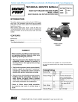
Electronic copies of the most current TSM issue can be found on the Viking Pump website at www.vikingpump.com
TECHNICAL SERVICE
SERVICE MANUAL
TECHNICAL
MANUALSECTION
TSM 750
POWER LOAD MONITOR
1 ofTSM
8
SECTION
750
MOTOR SHAFT OUTPUT POWER MEASUREMENTPAGE
POWER LOAD MONITOR
ISSUE
PAGE B 1 OF 7
MOTOR SHAFT OUTPUT POWER MEASUREMENT
ISSUE
A
CONTENTS
Introduction . . . . . . . . . . . . . . . . . . . . . . . . . . . .1
Introduction
1
Viking Part Numbers . . . . . . . . . . . . . . . . . . . . . . .1
Viking Part Numbers
1
Safety Information . . . . . . . . . . . . . . . . . . . . . . . .2
Wiring
2
Wiring
. . . . Selection
. . . . . . . . . . . . . . . . . . . . . . . . . 3
. 3
Transformer
Transformer
Operation Selection . . . . . . . . . . . . . . . . . . . . .4 .4
Operation .
. . . . . . . . . . . . . . . . . . . . . . . . . . .4 .5
LED
LED . .Auto
. . .Set
. . . . . . . . . . . . . . . . . . . . . . . . 4 .5
Programming
Auto Set . . . . . . . . . . . . . . . . . . . . . . . . . . . 4 .5
Programming .
. . .First
. . .Start
. . . . . . . . . . . . . . . . . . 4 .5
Setup . and
Setup and
First Start . . . . . . . . . . . . . . . . . . . . .5 5
Example
Example .
. . . . . . . . . . . . . . . . . . . . . . . . . . 6 .5
Technical Data
Technical Dimensions
Data . . . . . . . . . . . . . . . . . . . . . . . . . 6 .7
Dimensions .
. . . . . . . . . . . . . . . . . . . . . . . . .6 7
Parameters
Parameters .
. . . . . . . . . . . . . . . . . . . . . . . . .6 7
Terminals
Terminals
. . . . . List
. . . . . . . . . . . . . . . . . . . . . .6 7
Parameter
Parameter
List .
. . . . . . . . . . . . . . . . . . . . . . . 7 .7
Dismantle
and
Disposal
Dismantle
Warranty and Disposal . . . . . . . . . . . . . . . . . . . . .7 8
Warranty . . . . . . . . . . . . . . . . . . . . . . . . . . . . .8
Power Load Monitor
INTRODUCTION
This instruction manual describes the installation and
operation of the Power Load Monitor. Its function is to
supervise induction motor driven equipment and
provide alarms or motor shutdown when abnormal
conditions are detected. If the machine’s “normal” load
level is exceeded, the internal relay change state and
the alarm LED turns red. The output relay contact can
be used for alarm indication and/or machine shutdown.
The unit is intended for price sensitive applications that
only demand non-complex protection against under or
overload for motors up to 50A.
VIKING PART NUMBER
RATED MOTOR CURRENT (A)
2-E90-012-999-00
0.4 –10.0
2-E90-013-999-00
10.1 - 25.0
2-E90-014-999-00
26 - 50
Your shipment should contain the following items:
• Power Load Monitor
• Current transformer
• Instruction manual
Check carefully that the Power Load Monitor
complies with the motor’s input voltage and that the
current transformer rating is as stated on the
delivery packaging and that the contents have not
been damaged in shipping.
Shipment Contents
VIKING PUMP, INC.
● A Unit of IDEX Corporation ● Cedar Falls, IA 50613 USA
©2002
VIKING PUMP, INC. • A Unit of IDEX Corporation • Cedar Falls, IA 50613 USA
SAFETY INFORMATION AND INSTRUCTIONS
IMPROPER INSTALLATION, OPERATION OR MAINTENANCE OF PUMP MAY CAUSE SERIOUS INJURY
OR DEATH AND/OR RESULT IN DAMAGE TO PUMP AND/OR OTHER EQUIPMENT. VIKING’S WARRANTY
DOES NOT COVER FAILURE DUE TO IMPROPER INSTALLATION, OPERATION OR MAINTENANCE.
THIS INFORMATION MUST BE FULLY READ BEFORE BEGINNING INSTALLATION, OPERATION OR
MAINTENANCE OF PUMP AND MUST BE KEPT WITH PUMP. PUMP MUST BE INSTALLED, OPERATED
AND MAINTAINED ONLY BY SUITABLY TRAINED AND QUALIFIED PERSONS.
THE FOLLOWING SAFETY INSTRUCTIONS MUST BE FOLLOWED AND ADHERED TO AT ALL TIMES.
Symbol
Legend :
!
!
Danger - Failure to follow the indicated
instruction may result in serious injury
or death.
BEFORE opening any liquid chamber (pumping
chamber, reservoir, relief valve adjusting cap fitting,
etc.) be sure that :
● Any pressure in the chamber has been completely
vented through the suction or discharge lines or
other appropriate openings or connections.
● The pump drive system means (motor, turbine,
engine, etc.) has been “locked out” or otherwise
been made non-operational so that it cannot be
started while work is being done on the pump.
WARNING
WARNING
!
WARNING
● You know what material the pump has been
handling, have obtained a material safety data
sheet (MSDS) for the material, and understand
and follow all precautions appropriate for the safe
handling of the material.
!
!
!
!
WARNING
!
WARNING
BEFORE operating the pump, be sure all drive guards
are in place.
DO NOT operate pump if the suction or discharge
piping is not connected.
!
!
DO NOT place fingers into the pumping chamber or
its connection ports or into any part of the drive train
if there is any possibility of the pump shafts being
rotated.
DO NOT exceed the pumps rated pressure, speed, and
temperature, or change the system/duty parameters
from those the pump was originally supplied, without
confirming its suitability for the new service.
!
WARNING
BEFORE operating the pump, be sure that:
● It is clean and free from debris
● all valves in the suction and discharge pipelines
are fully opened.
● All piping connected to the pump is fully supported and correctly aligned with the pump.
● Pump rotation is correct for the desired direction
of flow.
!
WARNING
SECTION TSM 750
ISSUE
B
PAGE 2 OF 8
Warning - In addition to possible serious
injury or death, failure to follow the
indicated instruction may cause damage
to pump and/or other equipment.
INSTALL pressure gauges/sensors next to the
pump suction and discharge connections to monitor
pressures.
USE extreme caution when lifting the pump. Suitable
lifting devices should be used when appropriate. Lifting
eyes installed on the pump must be used only to lift
the pump, not the pump with drive and/or base plate.
If the pump is mounted on a base plate, the base plate
must be used for all lifting purposes. If slings are used
for lifting, they must be safely and securely attached.
For weight of the pump alone (which does not include
the drive and/or base plate) refer to the Viking Pump
product catalog.
DO NOT attempt to dismantle a pressure relief valve
that has not had the spring pressure relieved or is
mounted on a pump that is operating.
AVOID contact with hot areas of the pump and/or
drive. Certain operating conditions, temperature
control devices (jackets, heat-tracing, etc.), improper
installation, improper operation, and improper
maintenance can all cause high temperatures on the
pump and/or drive.
THE PUMP must be provided with pressure protection.
This may be provided through a relief valve mounted
directly on the pump, an in-line pressure relief valve,
a torque limiting device, or a rupture disk. If pump
rotation may be reversed during operation, pressure
protection must be provided on both sides of pump.
Relief valve adjusting screw caps must always point
towards suction side of the pump. If pump rotation is
reversed, position of the relief valve must be changed.
Pressure relief valves cannot be used to control pump
flow or regulate discharge pressure. For additional
information, refer to Viking Pump’s Technical Service
Manual TSM 000 and Engineering Service Bulletin
ESB-31.
THE PUMP must be installed in a matter that allows
safe access for routine maintenance and for inspection
during operation to check for leakage and monitor
pump operation.
WIRING
This wiring example shows how the Power Load Monitor
can be used to control the starting and stopping circuit of
the motor. Other wiring configurations are possible.
The current transformer must be placed in the same
phase that is connected to terminal 9, phase L1.
For single phase connection refer to Figure 2 for the
alternate single phase connection. To complete the
remaining wiring refer to Figure 1.
DANGER !
The monitor must be installed by qualified personal.
• Always disconnect, lockout, and tag out supply
circuits prior to installing.
• The installation must comply with standard and
local regulations.
• Study this manual thoroughly before installing and
using the Power Load Monitor.
• Pay special attention to this section and the parts
marked “CAUTION!” or “DANGER”.
• Should questions or uncertainties arise, please
contact your authorized Viking distributor.
FIGURE 1
Standard Wiring Three-Phase Motors
Note!
Removing or breaking the seal on the housing will
invalidate the warranty.
CAUTION !
If the START/ STOP is connected according to figure
1, it is recommended that terminals 6 and 7 be bypassed during settings. After the settings are
completed the by-pass must be taken out.
FIGURE 2
Single-Phase Wiring Example
LATCHED OR UN - LATCHED ALARM
Un-Latched (Auto Reset) when voltage supplied to
terminal 5 and 6. Latched Alarm when terminal 5 and
6 opened (not connected).
FIGURE 3.
Wiring Example For Latched Or Un-Latched Alarm
SECTION TSM 750
ISSUE
A
PAGE 2 OF 7
VIKING PUMP, INC. ● A Unit of IDEX Corporation ●
Cedar Falls, IA 50613 USA ©2002
SECTION TSM 750
ISSUE
B
PAGE 3 OF 8
CURRENT TRANSFORMER SELECTION
FOR MOTORS UP TO 50 A
1. Check the rated motor current on the motor plate.
2. Compare this value with the Rated Motor Current in
table 1.
3. From table 1, select the appropriate numbers of
windings for the current transformer.
CURRENT TRANSFORMERS
VIKING PART
NUMBER
2-E90-012-999-00
2-E90-013-999-00
2-E90-014-999-00
TRANSFORMER
MODEL
CTM010
CTM025
CTM050
RATED MOTOR
CURRENT (A)
0.40-1.00
10
1.01– 2.00
5
2.01–3.00
3
3.1-5.0
2
5.1-10.0
1
10.1-12.5
2
12.6-25.0
1
26-50
1
TABLE 1
Current Transformer And Number Of Primary Windings
DANGER !
Terminals 1 and 2 (s1, s2) carry line voltage.
EXAMPLE
• Rated motor current = 12 A.
• Select 10. 1 - 12. 5 from the first column in table 1 and
choose 2-E90-013-999-00 with two (2) primary windings.
Note!
Maximum length of CTM cable is 39 inches (1 m).
FIGURE 4
Example: CTM O25 With 2 Windings For 12 A Motor
Note!
Normally the appropriate current transformer will have
been ordered and shipped with the Power Load Monitor,
check that this is the case; contact the supplier if in doubt.
Note!
The transformer connection and orientation are not polarity
sensitive.
VIKING PUMP, INC. ● A Unit of IDEX Corporation ●
Cedar Falls, IA 50613 USA ©2002
SECTION TSM 750
ISSUE
B
PAGE 4 OF 8
FIGURE 5
Example 1 And 3 Windings.
SECTION TSM 750
ISSUE
A
PAGE 3 OF 7
OPERATION
LED
• A constant green LED indicates a parameter type.
pressing
• A flashing green
LEDPAR.
indicates a value.
OPERATION
Under
normal system operation, the eight LED's are all
off (see table 2). Any LED's illuminated will be
automatically switched off 30 seconds after the last
key press.
AUTO SET
The alarm load level is automatically set by the Auto
Set function (see Programming). The value for a
parameter, e.g. seconds, kW, HP or margin, can only
be set as 0, 1, 2, 4, 8, 16, 32 or 64. Select closest
value.
PROGRAMMING
Set up the monitor as below:
Current Input
Terminal 1 and 2. Current
Transformer; CTM 010,
025, or 050 (Max 50 A
motor).
Reset Input
Terminal 5 and 6 are
used for external reset
and selection of
latched/unlatched alarm.
Relay Output
Terminal 6, 7 and
8 output relay.
CAUTION!
Make sure that all safety measures have been
taken before switching on the supply voltage and
starting the motor/ machine in order to avoid
personal injury.
Verify that suction and discharge lines are
connected and tight, valves are open and liquid is
flowing under normal conditions to the pump before
beginning to set the Power Load Monitor for normal
operating conditions.
SET- UP AND FIRST START
1. Switch on the supply voltage - Power LED turns
green.
2. Press PAR once - “LED” AUTO SET turns green.
3. Keep pressing PAR until the desired parameter is
selected e. g. RATED POWER, see table 2 and 3.
4. Press VAL - Factory set value or earlier set value
flashes e. g. “64”.
5. Keep pressing VAL until desired value is displayed
(0 - 64).
6. Confirm chosen value by pressing PAR.
7. Press PAR again and repeat steps 3 to 6 for all
parameters except for AUTO SET. See tables 2, 3
and fig. 6 for possible value setting for each of the
eight parameters.
8. Start and run motor/system at normal load conditions,
also wait until the START DELAY has expired.
Power/ Alarm
The Power/ Alarm
LED indicates
green at "power
on" and at normal
load. Red at
alarm.
PAR
Parameter
change (LED
light constant
green) -pressing
PAR key when
parameter is
displayed
VAL
Value setting Pressing VAL
key when green
LED is flashing
increases value. A
changed value is
confirmed by
pressing PAR.
Motor Terminals
Terminal 9 (L1), 11 (L2), and 13 (L3)
for supply and motor voltage input.
Reset
Reset a latched alarm by
pressing both PAR and VAL at
the same time for 3 seconds.
Hint!
Short-circuit the output relay during the set-up, this
prevents the equipment from stopping unintentionally, see
Caution! in section “Wiring”.
9. Press PAR once - “LED” AUTO SET turns green.
10. Press and hold VAL for 3 seconds, at normal
machine load. The Auto Set load level is
automatically set and the LED is switched off.
11. Set/re-set e.g. start delay, response delay, margin
etc. if necessary (see table 2, 3, and figure 6).
SECTION TSM 750
ISSUE
A
PAGE 4 OF 7
VIKING PUMP, INC. ● A Unit of IDEX Corporation ●
Cedar Falls, IA 50613 USA ©2002
SECTION TSM 750
ISSUE
B
PAGE 5 OF 8
EXAMPLE: PUMP WITH OVERLOAD
PROTECTION
Pump with overload protection, motor 11 kW (fig. 6).
1. Check output power on motor plate and see table 3
(11 kW =Rated Motor Power 6.1- 12) -setting 8.
2. Switch on the supply voltage - Power LED green.
3. Press PAR once - “LED” AUTO SET turns green.
4. Keep pressing PAR until RATED POWER is
selected.
5. Press VAL - Value “64” flashes (factory setting).
6. Set recommended value according to table 3. Keep
pressing VAL until chosen value (8) flashes.
7. Confirm chosen value by pressing PAR.
8. Press PAR again and select MAX.
9. Press VAL . Choose the factory setting MAX Overload Protection – “1”.
10. Confirm chosen value (1) by pressing PAR.
11. Press PAR again and select RELAY INVERTED.
12. Press VAL. Choose the factory setting “no” =“0”.
13. Confirm chosen value (0) by pressing PAR.
The above parameters are necessary to set for safe
functioning. Note that “Rated Power” for the motor must be
set before Auto Set.
CAUTION!
Positive displacement pumps require some form of
over-pressure protection to be placed in the discharge
line in conjunction with the Power Load Monitor.
Pressure spikes created by sudden discharge line
blockage may cause serious pump damage.
VALUE
PARAMETER
RATED POWER
RELAY INVERTED
0 1 2 4 8 16 32 64
0(no) 1(yes)
ALARM CURRENT= 0
0(no) 1(yes)
FACTORY
SETTING
64
0
0
MAX OR MIN
0(MIN) 1(MAX)
1
RESPONSE DELAY
0 1 2 4 8 16 32 64
2
START DELAY
MARGIN
(% of rated power)
AUTO SET
0 1 2 4 8 16 32 64
0 1 2 4 8 16 32 64
2
8
Autoset load level
is automatically set
if VAL key is
pressed for 3
seconds
NOTE
See Table 3
0=Relay Activated
alarm
Alarm at no motor
current
0=underload
1=overload
Response delay in
seconds (0=50ms)
Start delay in seconds
Load change for alarm
sensitivity. Fig 6
VAL key must be
pressed when LED
parameter AUTOSET
is lit. LED bar is
switched off when
Autoset level is set.
TABLE 2
Parameters and Values
RATED MOTOR POWER IN HP
OR Kw
0 – 0.5
0.51 - 1.5
1.51 - 2.5
2.51 - 6
6.1 - 12
12.1 - 24
24.1 - 48
48.1 - 75
SETTING
0
1
2
4
8
16
32
64
TABLE 3
Setting or Rated Motor Power
POWER
Hints!
Change the load on the machine to find out if
appropriate load limit margin is set correctly. You can
also reduce the margin by one or more steps to find
out at what level the machine will trip. See figure 6.
Set/Reset e.g. start delay, response delay, trip margin
etc. if necessary (see table 2).
If the alarm level is difficult to set - simply perform an
Auto Set when the motor is stopped. Then start the
machine, run at normal load and perform an Auto Set
again.
If a wrong value is unintentionally set - simply set a
new value. If the value is not confirmed by pressing
PAR, the new value is not accepted (time out after 30
seconds).
VIKING PUMP, INC. ● A Unit of IDEX Corporation ●
Cedar Falls, IA 50613 USA ©2002
SECTION TSM 750
ISSUE
B
PAGE 6 OF 8
Overload
(MAX)
Alarm Level
(overload monitor)
Margin
Power at AUTO SET
(Auto set load level)
Margin
Alarm Level
(underload monitor)
t
FIGURE 6
Alarm Level and Margin
SECTION TSM 750
ISSUE
A
PAGE 5 OF 7
TECHNICAL DATA
Dimensions
(WxHxD)
1.77” x 3.54”x4.53 “ (45x90x115mm)
Mounting
35mm DIN-rail 46277
Weight
Supply Voltage
5.65 oz. (175g)
Frequency
Current Input
50 or 60 Hz
Power Consumption
Max 3 W
Start-up Delay
Response Delay
Relay Output
1-64 seconds
0.05–64 seconds
Fuse
Max 10 A
Terminal Wire Size
Use 75° C copper (CU) wire only.
0.2-4.0 mm2 single core (AWG12)
0.2-2.5 mm2 flexible core (AWG14)
Strip length 0.32” (8mm)
1x100-240 (±10%)
3x100-600 (±10%)
3x600-690 (±10%)
Current Transformer CTM 010,025, or 050
(max 50 A motor)
5 A/240 VAC Resistive, 1.5 A/240 VAC Pilot Duty/AC12
Terminal Tightening
Torque
Repeatability
Temperature Tolerance
5-7 lb-in (0.56-0.79 Nm)
± 2.5% FS, 24H @ 77°F (25°C)
<0.1%/ °C
External RESET on
Terminal 5
Max 240VAC or 48 VDC
High :> 24VAC/DC Low: < 1VAC/DC
Operating Temperature
4-122°F (-20-+50°C)
Storage Temperature
22-176°F (-30-+80°C)
Protection Class
Approved To
IP20
CE, cUL (UL up to 600V)
TERMINALS
PARAMETER LIST
TERMINAL
LABEL
1
S1
FUNCTION
Current transformer input for CTM 010,
1
CTM 025,CTM 050
2
S2
Current transformer input
3
4
5
RES
6
C
7
8
9
NC
NO
L1
1
Reset input. Latched or unlatched alarm
is selected via this input.
Alarm relay common and also reset
common
PARAMETER
FACTORY
SETTING
Rated Power
Relay Inverted
Alarm Current = 0
Max or Min
Response Delay
Start Delay
Margin
64
0
0
1
2
2
8
ACTUAL
SETTING
ALTERNATE
SETTING
Alarm relay is normally closed.
Alarm relay is normally open.
Motor voltage phase L1
10
11
L2
Motor voltage phase L2 ( N for single
2
phase motors)
L3
Motor voltage phase L3 (N for single
2
phase motors)
12
13
1 Note Terminals 1 and 2 (S1, S2) carry Line voltage
2 N Must be connected to terminal 11 and 13 (single phase)
SECTION TSM 750
ISSUE
A
PAGE 6 OF 7
VIKING PUMP, INC. ● A Unit of IDEX Corporation ●
Cedar Falls, IA 50613 USA ©2002
SECTION TSM 750
ISSUE
B
PAGE 7 OF 8
TECHNICAL SERVICE MANUAL
POWER LOAD MONITOR
MOTOR SHAFT OUTPUT POWER MEASUREMENT
SECTION
TSM 750
PAGE
8 of 8
ISSUE
B
DISMANTLING AND DISPOSAL
The housing is made of recyclable plastic, PC/ ABS
and the circuit board contains small amounts of tin and
lead. When disposing, the parts must be handled and
recycled in accordance with local regulations.
WARRANTY
EU (EUROPEAN UNION) SPECIFICATIONS
EMC EN 50081- 1, EN 50081- 2,
EN 50082- 1, EN 61000- 6- 2
Electrical safety IEC 947- 5- 1
Rated insulated voltage 690 V
Rated impulse withstand voltage 4000V
Pollution degree 2
Terminals 5, 6, 7 and 8 are basic insulated from the
line.
Viking warrants all products manufactured by it to be
free from defects in workmanship or material for a
period of one (1) year from date of startup, provided
that in no event shall this warranty extend more than
eighteen (18) months from the date of shipment from
Viking. The warranty period for Universal Seal series
pumps ONLY (Universal Seal models listed below) is
three (3) years from date of startup, provided that in
no event shall this warranty extend more than forty-two
(42) months from the date of shipment from Viking.
US SPECIFICATIONS
FCC (Federal Communications Commission)
This equipment has been tested and found to comply
with the limits for a class A digital device pursuant to
the Part 15 of the FCC Rules.
These limits are designed to provide reasonable
protection against harmful interference when the
equipment is operated in a commercial environment.
This equipment generates, uses and can radiate radio
frequency energy and, if not installed and used in
accordance with the instruction manual, may cause
harmful interference, in which case, the user will be
required to correct the interference at their own
expense.
UNDER NO CIRCUMSTANCES SHALL VIKING BE
LIABLE UNDER THIS WARRANTY OR OTHERWISE
FOR
SPECIAL,
INCIDENTAL,
INDIRECT,
CONSEQUENTIAL OR PUNITIVE DAMAGES OF ANY
KIND, INCLUDING, BUT NOT LIMITED TO, LOST
OR UNREALIZED SALES, REVENUES, PROFITS,
WARRANTY
INCOME, COST SAVINGS
OR BUSINESS, LOST OR
UNREALIZED CONTRACTS, LOSS OF GOODWILL,
DAMAGE TO REPUTATION, LOSS OF PROPERTY,
Viking warrants all products manufactured by it to
LOSS
OF from
INFORMATION
OR DATA, or
LOSS
OF for a
be free
defects in workmanship
material
PRODUCTION,
DOWNTIME,
OR of INCREASED
period of one (1)
year from date
startup, provided
COSTS,
ANYextend
PRODUCT,
that inIN
noCONNECTION
event shall thisWITH
warranty
more than
EVEN
IF
VIKING
HAS
BEEN
ADVISED
OR
PLACED from
eighteen (18) months from the date of shipment
ONViking.
NOTICE
OF THE
POSSIBILITY
OFany
SUCH
If, during
said warranty
period,
products
DAMAGES
THE
sold by AND
VikingNOTWITHSTANDING
prove to be defective
in FAILURE
workmanship
OF or
ANY
ESSENTIAL
ANY
PRODUCT.
material
under PURPOSE
normal useOF
and
service,
and if such
CANADA SPECIFICATIONS
DOC (Department of communications)
This digital apparatus does not exceed the Class A
limits for radio noise emissions from digital apparatus
as set out in the Canadian interference- Causing
Equipment Regulations. Le présent appareil numérique
n'ément pas de bruits radio- électriques dépassant les
limites applicables aux appareils numériques de la
Classe A prestite dans le Régelement sur le brouillage
radioélectrique édicté du Canada.
products are returned to Viking’s factory at Cedar
THIS WARRANTY IS AND SHALL BE VIKING’S SOLE
Falls, Iowa, transportation charges prepaid, and if the
AND
EXCLUSIVE
WARRANTY
AND toSHALL
BE IN in
products
are found
by Viking
be defective
LIEU
OF ALL OTHER
WARRANTIES,
EXPRESS
workmanship
or material,
they will be
replaced or
ORrepaired
IMPLIED,
BUT
NOT
LIMITED
free INCLUDING,
of charge, FOB.
Cedar
Falls,
Iowa.
VikingWARRANTIES
assumes noOFliability
for consequential
TO, ALL
MERCHANTABILITY,
damages
kind and PURPOSE
the purchaser
FITNESS
FORof A any
PARTICULAR
AND by
acceptance of delivery
all liability
for the
NON-INFRINGEMENT
ALL assumes
OF WHICH
OTHER
consequences of the use or misuse of Viking
WARRANTIES
EXCLUDED.
products byARE
the EXPRESSLY
purchaser, his
employees or others.
willwarranty
assumeatno
field expense for service or
SeeViking
complete
www.vikingpump.com.
parts unless authorized by it in advance.
Equipment and accessories purchased by Viking
from outside sources, which are incorporated into
any Viking product, are warranted only to the extent
of and by the original manufacturer’s warranty or
guarantee, if any.
THIS IS VIKING’S SOLE WARRANTY AND IS IN
LIEU
OF
ALL
OTHER
WARRANTIES,
EXPRESSED OR IMPLIED, WHICH ARE HEREBY
EXCLUDED, INCLUDING IN PARTICULAR ALL
WARRANTIES OF MERCHANTABILITY OR
FITNESS FOR A PARTICULAR PURPOSE. No
officer or employee of IDEX Corporation or Viking
Pump, Inc. is authorized to alter this warranty.
VIKING PUMP, INC. • A Unit of IDEX Corporation • Cedar Falls, IA 50613 USA
© 3/2013 Viking Pump Inc.
All rights reserved