1
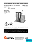
OPERATOR MANUAL &
SERVICE MANUAL
IMPORTANT INFORMATION, KEEP FOR OPERATOR
This manual provides information for:
MODELS TA/3 Domestic
INCLINED MIXER
ASSEMBLY
· Stainless Steel
· Tilt-Out Drive System
· Speed Agitator Controls
· For 40, 60 & 80 Gallon Kettles
DEE 4/T - (40, 60) TA/3
DHT - (40, 60) TA/3
D - (40, 60) TA/3
THIS MANUAL MUST BE RETAINED FOR FUTURE REFERENCE.
READ, UNDERSTAND AND FOLLOW THE INSTRUCTIONS AND
WARNINGS CONTAINED IN THIS MANUAL.
WARNING
Do not store or use gasoline or other flammable vapors and
liquids in the vicinity of this or any other appliance.
NOTIFY CARRIER OF DAMAGE AT ONCE
It is the responsibility of the consignee to inspect the container upon receipt of
same and to determine the possibility of any damage, including concealed damage. Unified Brands suggests that if you are suspicious of damage to make a
notation on the delivery receipt. It will be the responsibility of the consignee to file
a claim with the carrier. We recommend that you do so at once.
Manufacture Service/Questions 888-994-7636.
Information contained in this document is known to be current and accurate at the time
of printing/creation. Unified Brands recommends referencing our product line websites,
unifiedbrands.net, for the most updated product information and specifications.
PART NUMBER 141909, REV. B (7/06)
1055 Mendell Davis Drive
Jackson, MS 39272
888-994-7636, fax 888-864-7636
groen.com
OM/TA/3
IMPORTANT — READ FIRST — IMPORTANT
2
2
TA/3 141909 REV. B
WARNING:
THE MIXER MUST BE INSTALLED BY PERSONNEL WHO ARE QUALIFIED TO WORK WITH
ELECTRICITY, IMPROPER INSTALLATION CAN RESULT IN INJURY TO PERSONNEL AND/OR
DAMAGE TO EQUIPMENT.
WARNING:
ANY MECHANICAL OR ELECTRICAL CHANGE MUST BE APPROVED BY THE GROEN FOOD
SERVICE ENGINEERING DEPARTMENT.
WARNING:
TURN OFF AGITATOR BEFORE ADDING INGREDIENTS OR INSPECTING KETTLE CONTENTS.
DO NOT WEAR LOOSE CLOTHING OR JEWELRY AROUND OPERATING MIXER KETTLE.
KEEP WELL CLEAR OF ROTATING MIXER ARMS AND PADDLES AT ALL TIMES.
WARNING:
THE UNIT IS EQUIPPED WITH AN AUTOMATIC CUTOFF SWITCH. IF POWER IS ON WHEN A
TILTED MIXER IS LOWERED INTO THE OPERATING POSITION, THE MIXER WILL
AUTOMATICALLY START.
CAUTION:
STARTING WITH THE MIXER SET AT HIGH SPEED MAY CAUSE MATERIAL TO SPILL OUT OF
THE KETTLE ONTWO SPEED AND VARIABLE SPEED UNITS.
CAUTION:
UNDER HEAVY LOAD DO NOT RUN THE MIXER CONTINUOUSLY AT SLOWER THAN 5% OF
FULL SPEED. SLOWER OPERATION COULD DAMAGE THE SPEED CONTROL.
WARNING:
BEFORE CLEANING ANY PART OF THE MIXER, OTHER THAN THE AGITATOR, DISCONNECT
THE ELECTRICAL SUPPLY AT THE CIRCUIT BREAKER OR FUSE BOX TO AVOID POSSIBLE
ELECTRICAL SHOCK.
WARNING:
KEEP WATER AND SOLUTIONS OUT OF THE CONTROLS, ELECTRICAL WIRING, AND DRIVE
MECHANISM. NEVER SPARY OR HOSE THE MIXER.
CAUTION:
WHEN YOU INSTALL THE SCRAPER BLADES, MAKE SURE THE SCRAPER IS CURVED. A
REVERSED SCRAPER WILL NOT SCRAPE AND CAN CAUSE SERIOUS DAMAGE.
WARNING:
AVOID CONTACT WITH CEANING PRODUCTS IN ACCORDANCE WITH SUPPLIER AND
MANUFACTURER RECOMMENDATIONS. MANY CLEANERS ARE HARMFUL TO THE SKIN,
EYES, MUCOUS MEMBRANES AND CLOTHING. READ THE WARNINGS AND FOLLOW
DIRECTIONS ON THE CLEANER LABEL.
WARNING:
USE OF ANY REPLACEMENT PARTS OTHER THAN THOSE SUPPLIED BY GROEN OR THEIR
AUTHORIZED DISTRIBUTOR VOIDS ALL WARRANTIES AND CAN CAUSE BODILY INJURY TO
THE OPERATOR AND DAMAGE TO THE EQUIPMENT.
WARNING:
SERVICE PERFORMED BY OTHER THAN FACTORY AUTHORIZED PERSONNEL WILL VOID
ALL WARRANTIES.
WARNING:
BEFORE REPLACING ANY PARTS, SHUT OFF ALL ELECTRIC POWER SUPPLIES TO THE
COOKER/MIXER.
WARNING:
USE ONLY GROEN-SUPPLIED PARTS. SUBSTITUTION OF UNAUTHORIZED OR GENERIC
PARTS CAN RESULT IN BODILY INJURY TO THE OPERATOR AND DAMAGE TO THE
EQUIPMENT.
141909 REV. B TA/3
3
OM/TA/3
WARNING
DO NOT PLACE HANDS, TOOLS, OR HOSES IN KETTLE
WHILE AGITATOR IS MOVING
AGITATOR INSTRUCTIONS
*WARNING* AGITATOR AREA MUST BE CLEAR OF OBSTRUCTION BEFORE OPERATION
TO RUN AGITATOR
ENSURE KETTLE IS FULLY UPRIGHT
ENSURE MIXER HEAD IS FULLY DOWN AND LATCHED
SET THE SPEED DIAL TO DESIRED SPEED
TURN THE START SWITCH TO ON
TO STOP AGITATOR
PRESS THE RED STOP BUTTON OR TURN THE SWITCH TO OFF
WARNING
DO NOT PLACE HANDS, TOOLS, OR HOSES IN KETTLE
WHILE AGITATOR IS MOVING
4
4
TA/3 141909 REV. B
OM/TA/3
Table of Contents
IMPORTANT OPERATOR WARNINGS . . . . . . . . . . . . . . . . . . . . . . . . . . . . . . . . . . . . . . . . . . . . . . . . . . 2
REFERENCES . . . . . . . . . . . . . . . . . . . . . . . . . . . . . . . . . . . . . . . . . . . . . . . . . . . . . . . . . . . . . . . . . . . . . . 5
EQUIPMENT DESCRIPTION . . . . . . . . . . . . . . . . . . . . . . . . . . . . . . . . . . . . . . . . . . . . . . . . . . . . . . . . . . 6
INSTALLATION AND START-UP . . . . . . . . . . . . . . . . . . . . . . . . . . . . . . . . . . . . . . . . . . . . . . . . . . . . . . . 7
OPERATION . . . . . . . . . . . . . . . . . . . . . . . . . . . . . . . . . . . . . . . . . . . . . . . . . . . . . . . . . . . . . . . . . . . . . . . 7
CLEANING . . . . . . . . . . . . . . . . . . . . . . . . . . . . . . . . . . . . . . . . . . . . . . . . . . . . . . . . . . . . . . . . . . . . . . . . . 8
MAINTENANCE . . . . . . . . . . . . . . . . . . . . . . . . . . . . . . . . . . . . . . . . . . . . . . . . . . . . . . . . . . . . . . . . . . . . 10
TROUBLESHOOTING . . . . . . . . . . . . . . . . . . . . . . . . . . . . . . . . . . . . . . . . . . . . . . . . . . . . . . . . . . . . . . . 11
PARTS LIST . . . . . . . . . . . . . . . . . . . . . . . . . . . . . . . . . . . . . . . . . . . . . . . . . . . . . . . . . . . . . . . . . . . . . . . 12
ELECTRICAL SCHEMATIC . . . . . . . . . . . . . . . . . . . . . . . . . . . . . . . . . . . . . . . . . . . . . . . . . . . . . . . . . . . 19
SERVICE LOG . . . . . . . . . . . . . . . . . . . . . . . . . . . . . . . . . . . . . . . . . . . . . . . . . . . . . . . . . . . . . . . . . . . . . 20
WARRANTY . . . . . . . . . . . . . . . . . . . . . . . . . . . . . . . . . . . . . . . . . . . . . . . . . . . . . . . . . . . . . . . . . . . . . . . 2 1
References
NATIONAL FIRE PROTECTION ASSOCIATION
60 Battery March Park
Quincy, Massachusetts 02269
NFPA/70
The National Electrical Code
5
141909 REV. B TA/3
5
Equipment Description
The Groen TA/3 assembly is an electrically
powered mixer with dual counter rotating
agitators, which is incorporated into Groen
kettles of 40 to 80 gallon capacity.
OM/TA/3
The secondary, counter rotating agitator is
constructed of stainless steel and is easily
removeable.
The mixer has a variable speed drive with
electrical speed control.
The main agitator is anchor type and of
tubular stainless steel and fitted with scraper
fingers. Both the scraper fingers and the
agitator assembly are easily removed.
For a description of the kettle component of
your cooker/mixer, see the separate kettle
manual.
Installation and Start-Up
deck to reduce chances that the unit could
tip over if unit is provided with flanged feet.
2. Provide the proper electric power supply as
specified on the electrical information plate
attached to the mixer. Observe local codes
and/or The National Electrical Code in
accordance with ANSI/NFPA 70 - latest
edition. The installation must conform to the
code that has the more strict requirements.
WARNING
TURN OFF POWER AT THE CIRCUIT
BREAKER PRIOR TO INSTALLATION.
THE MIXER MUST BE INSTALLED BY
PERSONNEL WHO ARE QUALIFIED TO
WORK WITH ELECTRICITY. IMPROPER
INSTALLATION CAN RESULT IN INJURY TO
PERSONNEL AND/OR DAMAGE TO
EQUIPMENT.
3. Your mixer requires a permanent connection
with the electrical service. Use waterproof
conduit and waterproof connectors for this
connection.
4. Any electrical service for the kettle will
require a separate connection. See the
specific kettle manual.
ANY MECHANICAL OR ELECTRICAL
CHANGE MUST BE APPROVED BY THE
GROEN FOOD SERVICE ENGINEERING
DEPARTMENT.
Your Groen mixer has been test operated at the
factory and is furnished with all internal wiring. It
is complete and ready for final connection. A
wiring diagram is furnished at the rear of this
manual.
WARNING
TO PREVENT POSSIBLE ELECTRIC SHOCK,
GROUND THE UNIT AT THE TERMINAL
PROVIDED.
A. Installation is as follows:
1. Set the cooker/mixer in place and level it. If
the mixer is a tilting model, confirm that
there is enough rear or side clearance,
depending on model, and overhead
clearance to tilt the mixer safely through its
entire tilting range. Provide enough
clearance to permit access for service as
well. Fasten the cooker/mixer to the floor or
5. Use the following check list to confirm that
the installation is correct.
Unit level
6
6
TA/3 141909 REV. B
OM/TA/3
WARNING
TURN OFF AGITATOR BEFORE ADDING
INGREDIENTS OR INSPECTING KETTLE
CONTENTS. DO NOT WEAR LOOSE
CLOTHING OR JEWELRY
AROUND
OPERATING MIXER KETTLE. KEEP WELL
CLEAR OF ROTATING MIXER ARMS AND
PADDLES AT ALL TIMES.
Adequate clearance for tilting
Access for service
Unit fastened down
Mixer power supply conforms to
information plate and code
Electrical conduit and connections are
waterproof
Mixer grounded
For instructions on installing the kettle
component of your cooker/mixer, see the
separate kettle manual.
B. Initial Start-Up
After the mixer is installed, take the following
actions to confirm that the equipment is
operating correctly.
1. For a tilting model, tilt the mixer through its
complete tilting range to ensure that there is
no hazard or interference.
2. Make sure the agitator is properly coupled
with its drive shaft. The mixer has a slip-on
coupling, the drive pin must be positioned at
the end of the J-slot. (See photograph 1)
Photo 1: Slip-on Coupling
3. Carefully examine the primary agitator to
verify that eath finger is positioned correctly
as shown in figure 1.1.
4. When the mixer is in operating position,
each scraper blades should touch the inside
of the kettle during at least part of each
revolution of the agitator.
5. At the circuit breaker or fuse box, turn on the
electric power supply to the mixer.
6. Switch on the drive and confirm that the
mixer operates smoothly throughout its
speed range.
7. Make sure the agitator turns in the correct
direction, so it pushes the nylon scraper
blades ahead of the agitator bar.
If the unit functions as described above, it is
ready for use. If the unit does not function as
intended, call your local Groen authorized
service agency.
Figure 1.1
For instructions on initial start-up of the kettle
component of your cooker/mixer, see the
separate kettle manual.
7
141909 REV. B TA/3
7
OM/TA/3
Operation
WARNING
TURN OFF AGITATOR BEFORE ADDING INGREDIENTS OR INSPECTING KETTLE CONTENTS. DO
NOT WEAR LOOSE CLOTHING OR JEWELRY AROUND OPERATING MIXER KETTLE. KEEP WELL
CLEAR OF ROTATING MIXER ARMS AND PADDLES AT ALL TIMES.
1. Before you operate the mixer, make sure
that the agitator is firmly connected with the
drive shaft and properly positioned in the
kettle. The agitator must be positioned so
every scraper blade touches the kettle
during at least part of each revolution. To
connect the agitator:
5. Set the desired mixing speed.
CAUTION
STARTING WITH THE MIXER SET AT HIGH
SPEED MAY CAUSE MATERIAL TO SPILL
OUT OF THE KETTLE ON VARIABLE SPEED
UNITS.
a. Slip-on Coupling: Slide the coupling up
onto the shaft as far as it will go. Then
turn the agitator and pull it down, so that
the drive pin on the shaft becomes firmly
seated against the end of the J-slot.
a. On a variable speed drive with electrical
speed control, turn the speed
adjustment knob.
CAUTION
UNDER HEAVY LOAD DO NOT RUN THE
MIXER CONTINUOUSLY AT SLOWER THAN
5% OF FULL SPEED. SLOWER OPERATION
COULD DAMAGE THE SPEED CONTROL.
b. Bolted Coupling:
1. Guide the two pins of the drive shaft
into the holes in the coupling.
2. With the lobe of the cam pointing
up, and while holding the two cam
bolts, insert the bolts through the
larger holes in the side of the
coupling. The bolts must pass the
flat part of the shaft, and through the
smaller holes in the other side of the
coupling.
6. To stop the mixer, switch off the drive.
If the cooker/mixer will be cleaned or serviced,
or will not be used for a week or longer, cut
off all power supplies to the unit at the circuit
breaker or fuse box.
7. Switch off the drive, before you tilt the mixer.
To tilt the mixer, first unlatch it (See
Photograph). For some units, you may need
to tilt the kettle forward slightly to let the
agitator clear the kettle wall as you tilt the
mixer.
3. Turn the cam bolts toward the shaft
1/8 turn or until the lobe of the cam
is snug against the flat side of the
shaft.
8. As you tilt the mixer out of the kettle, clean
any clinging product from the agitator, so
product will not drip onto the outside of the
kettle or surroundings, and so the weight of
product will not make the mixer fall down.
4. Fasten the bolts in place with the
supplied hex nuts, and tighten the
nuts.
2. If the mixer has been tilted up, lower it into
operating position.
To operate the kettle component of your
cooker/mixer, see the separate kettle manual.
WARNING
THE UNIT IS EQUIPPED WITH AN
AUTOMATIC TILT CUTOFF SWITCH. IF
POWER IS ON WHEN A TILTED MIXER IS
LOWERED INTO OPERATING POSITION,
THE MIXER WILL AUTOMATICALLY START.
3. Turn on electric power to the unit at the
circuit breaker or fuse box.
ON/OFF
Switch
4. Switch on the drive.
8
8
TA/3 141909 REV. B
Emergency
3 Speed
Control Knob Stop Switch
OM/TA/3
Cleaning
A. Suggested Tools & Materials.
1. A good stainless steel cleaner.
2. Stiff brush.
3. Sanitizer Solution
B. Precautions
Photo 2
WARNING
BEFORE CLEANING ANY PART OF THE
MIXER, OTHER THAN THE AGITATOR, SHUT
OFF ALL ELECTRIC POWER TO THE
COOKER/MIXER AT THE CIRCUIT BREAKER
OR FUSE BOX, TO AVOID POSSIBLE
ELECTRIC SHOCK.
KEEP WATER AND SOLUTIONS OUT OF THE
CONTROLS, ELECTRICAL WIRING, AND
DRIVE MECHANISM. NEVER SPRAY OR
HOSE THE MIXER.
C. Procedure
1. Wash the agitator as soon as possible after
use. If the unit is in continuous use,
thoroughly clean and sanitize all parts of the
mixer at least once every 12 hours
Photo 3
2. Disassemble the scrapers and clean them
along with the rest of the agitator, then
reassemble them. To disassemble a scraper:
a.
Decouple both agitators from the drive shafts.
(see photo1 on page 7). Just lift the agitator
and rotate it in the "J" slot to decouple.
b.
Lay both agitators on flat surface (Photo 2)
c.
Remove hairpin clip from agitator (Photo 3)
d.
Remove scraper blades.
e.
Reverse procedure to assemble. CAUTION
- verify that the scraper blade is assembled
correctly. (See figure 1.1 on page 7)
9
141909 REV. B TA/3
9
OM/TA/3
agent from your supplier of sanitation
products. Following the supplier’s directions,
apply the sanitizer after the agitator has
been washed, then rinse off the sanitizer
completely. It is recommended that the
agitator be sanitized just before use.
CAUTION
WHEN YOU CONNECT THE SCRAPER WITH
THE YOKE, MAKE SURE THE SCRAPER IS
CURVED THE SAME WAY AS THE KETTLE.
A REVERSED SCRAPER WILL NOT SCRAPE
AND CAN CAUSE SERIOUS DAMAGE.
CAUTION
NEVER LEAVE A SANITIZER IN CONTACT
WITH THE SURFACE OF STAINLESS STEEL
LONGER THAN 20 MINUTES. LONGER
CONTACT CAN CAUSE CORROSION.
WARNING
AVOID CONTACT WITH ANY CLEANER, AS
RECOMMENDED BY THE SUPPLIER.
CAREFULLY READ THE WARNINGS AND
FOLLOW THE DIRECTIONS ON THE LABEL
OF THE CLEANER. MANY CLEANERS ARE
HARMFUL TO THE SKIN, EYES, MUCOUS
MEMBRANES, AND CLOTHING.
7. The exterior of the unit may be polished with
a good quality stainless steel cleaner.
Cleaning procedures for the kettle component of
your cooker/mixer are described in the separate
kettle manual.
3. Prepare a hot solution of the cleaning
compound as instructed by the supplier.
Wash the agitator parts and rinse them well.
Use a cloth moistened with the cleaning
solution to clean other parts of the mixer.
4. To remove materials stuck to the agitator,
use a brush, sponge, cloth, plastic or rubber
scraper, or plastic wool along with the
cleaning solution. To make washing easier,
let the cleaning solution soak into the
residue. When you clean the stainless steel
parts, do not use any abrasive material (like
metal sponges or scouring powder) or metal
implement (like a spoon, scraper, or wire
brush) that might scratch the surface.
Scratches make the surface hard to clean
and provide places for bacteria to grow. Do
not use steel wool, which may leave
particles imbedded in the surface and cause
eventual corrosion and pitting.
5. As part of the daily cleaning program, clean
all surfaces that may have been soiled.
Remember to check such parts as the back
and underside of the drive housing.
6. When the agitator needs to be sanitized, use
a sanitizing solution equivalent to one that
supplies 100 parts per million available
chlorine. Obtain advice on the best sanitizing
10
10
TA/3 141909 REV. B
OM/TA/3
Maintenance
B. Component Replacement
WARNING
USE OF ANY REPLACEMENT PARTS
OTHER THAN THOSE SUPPLIED BY GROEN
OR THEIR AUTHORIZED DISTRIBUTOR
VOIDS ALL WARRANTIES AND CAN CAUSE
BODILY INJURY TO THE OPERATOR AND
DAMAGE TO THE EQUIPMENT.
WARNING
BEFORE REPLACING ANY PARTS, SHUT
OFF ALL ELECTRIC POWER SUPPLIES TO
THE COOKER/MIXER.
All internal wiring is marked as shown on the
schematic drawings in this manual. Be sure that
new components are wired in the same manner
as the old components.
SERVICE PERFORMED BY OTHER THAN
FACTORY AUTHORIZED PERSONNEL WILL
VOID ALL WARRANTIES.
A. Periodic Service
C. Service Records
1. The interior of control and drive housings
should be kept clean and dry.
A Service Log is provided At the rear of this
manual. Each time service is performed on this
equipment, enter the date on which the work
was done, what was done, and who did it. Keep
this log with the equipment.
2. Electrical wiring should be kept securely
connected and in good condition.
Service procedures for the kettle component of
the cooker/mixer are described in the separate
kettle manual.
3. Regular service of the mixer should include
cleaning the motor and checking the reducer
gearcase. Check oil level at 3000hrs of
operation or every 6 months. Change oil
completely every 3 years or every 15,000
hours. Lubricant type is GG Artic SHC 23"
Food grade lubricant (Mobil product)
4.
Every six(6) months lubricate all grease
fittings on the transfer case with a USDA
approved food grade grease/lubricant.
Wipe off excess lubricant.
11
141909 REV. B TA/3
11
Troubleshooting
OM/TA/3
Your Groen Mixer will operate smoothly and efficiently if properly maintained. However, the following is a
list of checks to make in the event of a problem. If the actions suggested do not solve the problem, call
your authorized Groen Service Representative. For the phone number of the nearest agency, check the
Groen web site at www.groen.com, ask your area Groen representative or call the Groen Parts and
Service Department. If an item on the list is followed by X, the work should only be performed by a
qualified service representative.
WARNING
USE OF ANY REPLACEMENT PARTS OTHER THAN THOSE SUPPLIED BY GROEN OR THEIR
AUTHORIZED DISTRIBUTORS CAN CAUSE INJURY TO THE OPERATOR AND DAMAGE TO THE
EQUIPMENT AND WILL VOID ALL WARRANTIES.
SERVICE PERFORMED BY OTHER THAN FACTORY-AUTHORIZED PERSONNEL WILL VOID ALL
WARRANTIES.
SYMPTOM
Motor will not run.
Motor runs slowly.
Motor speed varies
rapidly.
WHO
WHAT TO CHECK
X indicates items which must be performed by an authorized technician.
User
a. Power supply to the unit.
b. For a mechanical overload. (example: frozen product)
c. Circuit breaker or fuse.
Auth Service
Rep Only
d. That the tilt switch is closed. X
e. For a ground or short in the motor. X
f. Overload heaters. X
User
a. For a mechanical overload.
Auth Service
Rep Only
b. For open motor field circuit, by checking field current. X
User
Auth Service
Rep Only
Motor overheats and/or User
sparks excessively.
Auth Service
Rep Only
Circuit breaker or heater User
cuts out frequently.
Auth Service
Rep Only
a. For an oscillating load, by disconnecting the mixer drive
from the agitator and checking motor speed.
b.
Variable speed controller X
a. For a mechanical overload.
b. Ambient temperature is high.
c. Incorrect supply voltage to motor. X
d. Excessive variation (under voltage or over voltage) in supply
voltage. X
e. Single phasing due to loose connection in supply line or a
blown fuse. X
a. For a mechanical overload.
b.
c.
d.
e.
f.
Whether line voltage is too high. X
Motor armature and wiring for ground or short. X
For open motor field circuit, by checking field current. X
For defective circuit breaker. X
Motor improperly connected. X
Troubleshooting guidance for the kettle component of your cooker/mixer is contained in the separate
kettle manual.
12
12
TA/3 141909 REV. B
OM/TA/3
Parts List
To order parts, contact your authorized Groen Service Agency. Supply the model designation, part
description, part number and quantity required. Where applicable, provide the voltage and phase as well.
WARNING
USE ONLY GROEN-SUPPLIED PARTS. SUBSTITUTION OF UNAUTHORIZED OR GENERIC
PARTS CAN RESULT IN BODILY INJURY TO THE OPERATOR AND DAMAGE TO THE
EQUIPMENT.
1
3
2
4
Diagram No.
Description
Part No.
1
Scraper Blade
006502
2
Hairpin Clip
012947
3
Agitator Secondary
009686 - 40 Gallon
009687 - 60 Gallon
009688 - 80 Gallon
4
Primary Agitator Assy.
009243 - 40 Gallon
009244 - 60 Gallon
009245 - 80 Gallon
13
141909 REV. B TA/3
13
Parts List
Description
Switch Assembly Agitator
Switch Assembly Speed Control
Switch Assembly Emergency Stop
Enclosure Nema
Enclosure , 12" x 16" x8"
Inverter 230 Vac
Inverter 380/460V
Terminal Block 3 - Pole
Contactor 12Amp 4 Pole
Fuse Block
Fuse 20 Amp
Transformer, 100 Va
Lug, Ground 14-6 AWG
W iring Kit, Variable Speed
Rel ay, Control
Soc ket Relay
W iring Schematic Variable
W iring Har ness
Wiring Harness Control Box
Wiring Harness Control Box to Agitator
Fuse Block (Type M) 3 Pole
Cover Agitator Tilt
Cover Inside Agitator
Bearing Roller
Shaft 3/4" Dia x 7-5/8" Long
Transfer Case Casting
Cover Transfer Case
Gasket 5/32" x 1/2"
Cover Transfer Case, Rear
Mercury Tilt Switch
Bracket For Tilt Switch
Front Transfer Case Assy,
Housing Front Bearing
Housing Eccentric Bearing
Housing Top Bearing
Washer Thrust
Bearing Cylindrical
Ring External
Pin Coupling 3/8" DIA
Key 1/4" Square x 2" Long
Shaft 1" x 11 - 1/2" Long
Gear Pinion
Gear Spur
Pin Coupling
Key 1/4" Square x 1-1/2" Long
Shaft, Motor for 135115
Set Collar
Plate, Motor & Drive Gear Assy
Screw, Socket Cap Grade 8
Part No.
128485
115341
115342
128458
128460
120436
128975
003888
111072
096809
071489
115356
119829
132383
115358
115359
128491
128482
128483
128484
120706
006972
006973
009212
009694
019640
009608
012323
132037
127408
128408
135336
009203
009204
009205
009208
009209
009223
009253
009258
009557
009268
009269
009305
009249
135117
012012
135119
115302
Description
Part No.
Handle & Latch Assy
044392
Bracket Arm Guide
002124
005474
Pin Taper #4 2" Long
009122
Snubber
009238
Handle & Brac ket Assy
012691
Knob Red Ball Handle
009718
Power Aid As sy
012889
Pin Poweraid Connection Top
012890
Pin Poweraid Connec tion
Plate Mounting
002153
Base Pivot and Poweraid Assy
128618
Agitator Primary 40 Gal
009243
Agitator Secondary 40 Gal
009686
Blade Fixed Scraper
001864
Scraper Finger Blade
006502
Holder Assy Scraper Top 40 Gal
010548
Holder Assy Scraper Bottom 40 Gal
010549
Holder Scraper Blade
001721
Clip Hairpin Tri-Cover
012947
Coupling Quick Disconnect
009304
Coupling Quick
009239
135822
Drive 1.5 HP, 208/360V
128979
Drive 2.0 HP, 240/480V
135578
Drive 1.5 HP, 240/480V
132099
Drive 2.0 HP, 208/360V
Mounting Plate
128519
Bracket Assy
128516
Gasket 5/32" x 1/2" x 50' Vertical Strip 002121
Gasket 5/32" x ½” x 50' w/ Adhesive
005233
Seal Cover Plate
006975
Base Pivot & Power Aid Assy
003662
Power Aid Assy
009719
Bearing Cylindrical
009722
Bearing Cylindrical
009724
Pin Power Aid Connection Top
012889
Ring Basic External
001538
Shaft 3/4" Dia x 7-5/8" Long
009694
Transfer Case Glass Bead
019641
001758
Shaft Seal
128989
Plate, Gearmotor Adaptor
009254
Gear Pinion
Gear Spur
009260
Shaft Extender
132026
Handle & Latch
041015
Handle & Bracket
009185
Handle & Spring
009181
012100
Fitting Grease #70
128379
Cover Plate
009244
Agitator Primary 60 Gal
010554
Holder Assy Scraper 60 Gal
14
14
TA/3 141909 REV. B
OM/TA/3
OM/TA/3
Description
Holder Scraper Blade
Holder Assy Scraper 60 Gal
Agitator Secondary 60 Gal
Agitator Primary 80 Gal
Agitator Secondary 80 Gal
Parts List
Part No.
001724
010557
009687
009245
009688
Description
Holder Assy Scraper 80 Gal
Holder Assy Scraper 80 Gal
Clip Hairpin
Part No.
010561
010563
012947
15
141909 REV. B TA/3
15
16
TA/3 141909 REV. B
12
11
2
3
1
19 25
4
8
7
14
9
21
20
21
8
6
19 25
3
2
28
27
23
24
15
2
3
1
16
19 25
5
8
9
22
13
26
10
18
23
16
17
29
4
4
1
4
4
REF.
4
1
3
1
1
1
1
1
1
1
1
1
2
3
1
1
1
1
12
12
2
QTY
REQD
26
24
23
22
21
20
19
18
17
16
15
14
13
12
11
10
9
8
7
6
5
4
3
2
1
ITEM
NO.
1
28
27
29
PART OR
IDENTIFYING NO.
005655
005610
009263
006009
128379
012100
012012
135117
009249
009305
009269
009268
009557
009258
009253
009223
009209
009208
009205
009204
009203
005656
005613
001758
135118
014830
115302
006029
OM/TA 3
NOMENCLATURE
OR DESCRIPTION
LOCKWASHER, 1/4"
BOLT, 1/4"-20 X 1/2" LONG
FRONT HOUSING, TRANSFER CASE
SCREW, ROUND HEAD, #10-32 X 3/8" LONG
COVER PLATE, SWITCH
FITTING GREASE, STRAIGHT
SET, COLLAR 1" ID
SHAFT, MOTOR DRIVE
KEY, 1/4" SQ. X 1-1/2" LONG
PIN, COUPLING 1/2" DIA
GEAR SPUR, 64-TEETH
GEAR, PINION (24) TEETH
SHAFT, 1" DIA. X 11-1/2" LG.
KEY, 1/4" SQ. X 2" LG. ROUND ENDS
PIN, COUPLING 3/8" DIA
RING, EXTERNAL
BEARING, CYLINDRICAL
WASHER THRUST, 1"
HOUSING, TOP BEARING
HOUSING, ECCENTRIC
HOUSING, FRONT BEARING
WASHER LOCK, 5/16"
SCREW, HEX HEAD CAP, 5-16"-18 X 1" LONG
SEAL, SHAFT
SPACING PLATE, MOTOR & DRIVE GEAR ASSY, EURODRIVE
LOCKWASHER, 7/16" DIA
SCREW, SOCKET CAP GRADE 8 5/15"-18 X1 1/2" LG
SCREW HEX HD CAP 7/16" - 14 X 1 1/2" LG
FRONT SECTION ASSEMBLY - 40 GALLON KETTLES
22
32
4
15
25
31 29 24
141909 REV. B TA/3
17
21
5
5
1
4
1
SCREW LOCATION
1
5
VIEW "A" SEE BELOW FOR SCREW LOCATION
1
5
1
4
1
3
3
6
6
6
A
8
11
10
9
9
10
17
MOUNTING CONFIGURATION FOR ITEMS: 8, 9, 10, 11, 12
12
9 10 11 12
FRAME ASSY.
8
12
27 28 30
26
11
8
2
4
4
1
4
2
1
1
4
1
1
1
1
1
37 IN
12
1
1
2
1
2
2
2
2
2
6
10
3
2
5
12
5
QTY
REQD
32
31
30
29
28
27
26
25
24
23
22
21
20
19
18
17
16
15
14
13
12
11
10
9
8
7
6
5
4
3
2
1
ITEM
NO.
OM/TA 3
NOMENCLATURE
OR DESCRIPTION
PARTS LIST
SCREW, HEX HEAD CAP, 5/8-11-X 3/4" LONG
SCREW, HEX HEAD CAP, 5/16-X 3/4" LONG
PIN, COTTER 1/8" DIA. X 1" LONG
PLATE MOUNTING, DTA/3-20-30-40
WASHER, PLAIN, 1/2" ID X .078" THK.
PIN, CONNECTING UPPER POWER AID
POWER AID ASSEMBLY, DTA/3-40
HANDLE & LATCH ASSEMBLY, MW/DTA/3-20-30-40 & DTA/3
WASHER, LOCK 5/16"-18
SCREW ROUND HEAD #8-32 X 5/8" LONG
TRANSFER CASE ASSY, FRONT ASSY.
BRACKET FOR TILT SWITCH MOUNTING
MERCURY TILT SWITCH-DURAKOOL #A1-003
PLATE COVER DTA/3 POWER AID CONNECTION
GASKET 5/32" X 1/2" W/ADHESIVE BACK
SCREW HEX HD CAP 1/4-20 X 5/8" 18-8 S
COVER PLATE, TRANSFER CASE, DTA/3
TRANSFER CASE BEAD FINISH POLISHED D-40, TA/3 CAST ALUMINUM
SCREW FLAT HD #3/8-16 X 3/4" LONG ZINC PLTD
SHAFT 3/4" DIA X 7-5/8" LONG FOR DTA/3
BEARING ROLLER W/O INNER RACE 1" ID X MCGILL #MR16N, MI12N
SEAL COVER PLATE GASKET 1/16 X 2-1/2" OD
WASHER COVER PLATE GASKET 3/4" ID X 2-1/2" OD X 1/16" THICK
COVER INSIDE AGITATOR TILT TRUNNION 11 GA 2-1/2" OD X 3/4" ID
COVER AGITATOR TILT TRUNNION 11 GA X 2-1/2" DIA DTA/3 ALUMINUM
SCREW, ROUND HEAD MACHINE #10-24 X 3/8" LONG 18-8
WASHER LOCK 1/2" MS ZN PLTD
SCREW HEX HD CAP 1/2"-13 X 1-3/4" LONG (USE SS)
SCREW HEX HD CAP 1/2"-13 X 2-1/4" LONG (USE #005628) MS ZN PLTD
NUT HEXAGON 1/2"-13 (HEAVY DUTY) MS ZINC PLTD
WASHER LOCK, 1/4"
SCREW HEX HEAD CAP 1/2-13 X 1-1/4" LONG 18-8
TRANSFER CASE ASSEMBLY - 40 GALLON UNITS
SEE MOUNTING CONFIGURATION BELOW
7
13
27 28 30
17 2
20 21 23
19
18
16
14
18
TA/3 141909 REV. B
29
21
5
6
3
5
3
26
6
30 31
26
27
SCREW LOCATION
3
6
3
6
VIEW "A" SEE BELOW FOR SCREW LOCATION
3
5
7
3
9
7
7
4
4
12
13
11
10
10
11
13
FRAME ASSY.
8
17
9 10 11 12 13
C
LOCATE VERTICAL BOTH SIDES
14 18 28
2
12
9
14 18 28 C
16
4
4
1
4
2
1
1
1
1
1
1
12
2
2
1
1
1
4
4
2
2
2
2
6
10
3
2
5
5
2
2
QTY
REQD
31
30
29
28
27
26
25
24
23
22
21
20
19
18
17
16
15
14
13
12
11
10
9
8
7
6
5
4
3
2
1
ITEM
NO.
SEE MOUNTING CONFIGURATION BELOW
MOUNTING CONFIGURATION FOR ITEMS: 9, 10, 11, 12, 13
A
20
D
PART OR
IDENTIFYING NO.
005656 ----005613 B-9097-380
041015 C-4876-007
005598 ----009878 ----128999 (60 Gal) 132034 (80 Gal)
007526 ----128408 ----122176 ----013873 A-5762-043
019641 ----078546 ----013466 ----013405 A-5762-004
009694 D-5762-014
012903 C-6820-002
132037 132037
009246 ----009212 ----006975 A-5762-037
006974 A-5762-037
006973 A-5762-038
006972 A-5762-038
006009 ----005735 ----005734 ----005728 ----005705 ----005623 ----005233 B-8588-001
002121 A-5762-047
LOCATE HOROZONTAL TOP AND BOTTOM
PARTS LIST
NOMENCLATURE
OR DESCRIPTION
WASHER, LOCK 5/16" 18-8
SCREW, HEXAGON HEAD CAP 5/16-18 X 1" LONG 18-8
HANDLE & LATCH ASSY DTA & MN/DTA/3-60
WASHER PLAIN 1/2" ID X .078" THICK FITS 1/2" 18-8
SCREW HEX HEAD CAP 5/8"-11 X 3/8" LONG
TRANSFER CASE ASSY (60 Gallon) ; (80 Gallon)
SCREW ROUND HEAD MACHINE #8-32 X 5/8" LONG MS ZN PLD
BRACKET FOR TILT SWITCH MOUNTING
MURCURY TILT SWITCH-DURAKOOL #A1-003
PLATE COVER/POWERAID CONNECTION DTA/3-40-60-80
TRANSFER CASE BEAD FINISH POLISHED DTA/3-60-80 CAST ALUMINUM
SCREW HEX HD CAP 1/4-20 X 5/8" 18-8 S
SCREW FLAT HD #3/8-16 X 3/4" LONG ZINC PLTD
PIN CONNECTION UPPER POWERAID 1/2" DIA. X 2-3/8" LONG DTA
SHAFT 3/4" DIA X 7-5/8" LONG FOR DTA/3
POWERAID ASSY. DTA/3-60
PLATE COVER DTA/3 W/O ELECTRICAL HOLE
PIN COTTER 1/8" DIA. X 1" LONG
BEARING ROLLER W/O INNER RACE 1" ID X MCGILL #MR16N, MI12N
SEAL COVER PLATE GASKET 1/16 X 2-1/2" OD
WASHER COVER PLATE GASKET 3/4" ID X 2-1/2" OD X 1/16" THICK
COVER INSIDE AGITATOR TILT TRUNNION 11 GA 2-1/2" OD X 3/4" ID
COVER AGITATOR TILT TRUNNION 11 GA X 2-1/2" DIA DTA/3 ALUMINUM
SCREW, ROUND HEAD MACHINE #10-24 X 3/8" LONG 18-8
WASHER LOCK 1/2" MS ZN PLD
SCREW HEX HD CAP 1/2"-13 X 1-3/4" LONG (USE SS)
SCREW HEX HD CAP 1/2"-13 X 2-1/4" LONG (USE #005628) MS ZN PLTD
NUT HEXAGON 1/2"-13 (HEAVY DUTY) MS ZINC PL
SCREW HEX HEAD CAP 1/2-13 X 1-1/4" LONG 18-8
GASKET 5/32" X 1/2" X 8" LONG W/ADHESIVE BACK
GASKET 5/32" X 1/2" X 10-1/8" VERTICAL STRIP W/ADHESIVE BACK
TRANSFER CASE ASSEMBLY 60 & 80 GALLON
23 24 25
22
1
15
19
141909 REV. B TA/3
19
Electrical Schematics
OM/TA/3
OM/TA/3
Service Log
Model No. _______________________________
Purchased From _________________________
Serial No. ______________________________
Location ________________________________
Date Purchased __________________________
Date Installed ____________________________
Purchase Order No. _______________________
For Service Call __________________________
Date
Maintenance Performed
20
20
TA/3 141909 REV. B
Performed by
OM/TA/3
LIMITED WARRANTY TO
COMMERCIAL PURCHASERS*
(U.S. & Canadian Sales Only.)
Groen warrants to original commercial purchaser/users that foodservice equipment manufactured by Groen
(“Groen Equipment”) (other than CapKold foodservice equipment) shall be free from defects in material and
workmanship for (12) twelve months from the date of installation or fifteen (15) months from date of shipment
from Groen, whichever date first occurs (the “Warranty Period”), in accordance with the following terms and
conditions:
I.
This warranty is limited to replacement parts and related labor for Groen Equipment located
at its original place of installation in the United States and Canada.
II.
Damage to Groen Equipment that occurs during shipment must be reported to the carrier,
and is not covered under this warranty. The reporting of any damage during shipment is the
sole responsibility of the commercial purchaser/user of such Groen Equipment.
III.
For Groen Convection ComboTM Steamer-Ovens, HyPerSteamTM Convection Steamers and
HyPlusTM Pressureless Steamers, Groen further warrants to the original commercial
purchaser/users of such Groen Equipment that the atmospheric steam generators or boilers
contained in such Groen Equipment shall be free from defects in material and workmanship
for twenty-four (24) months from the date of installation or twenty-seven (27) months from
date of shipment from Groen, whichever date first occurs, provided that: (a) the original
purchaser/user shall have also purchased and installed a Groen PureSteem Water
Treatment SystemTM for use in connection with such Groen Convection ComboTM SteamerOven, HyPerSteamTM Convection Steamer or HyPlusTM Pressureless Steamer on or before
the date such Groen Equipment was installed, (b) the original purchaser/user has
continuously used suchWater Treatment System in connection with such Groen Equipment
from the date of installation, and (c) the commercial purchaser/user shall have maintained
such Water Treatment System in accordance with the maintenance and filter cartridge
replacement recommendations of Groen, and otherwise maintained such Oven or Steamer
in accordance with all other operational and maintenance recommendations of Groen.
IV.
Groen further warrants to the original commercial purchaser/users of Groen Convection
ComboTM Steamer-Ovens that the electronic relay and control board contained in such Groen
Convection ComboTM Steamer-Oven shall be free from defects in material and workmanship
for twenty-four (24) months from the date of installation or twenty-seven (27) months from
date of shipment from Groen, whichever date first occurs.
V.
During the Warranty Period, Groen, directly or through its authorized service representative,
will either repair or replace, at Groen’s sole election, any Groen Equipment determined by
Groen to have a defect in material or workmanship. As to any such warranty service during
the Warranty Period, Groen will be responsible for related reasonable labor and portal to
portal transportation expenses (time & mileage) incurred within the United States and
Canada.
VI.
This warranty does not cover boiler maintenance, calibration, periodic adjustments as
specified in operating instructions or manuals, consumable parts (such as scraper blades,
gaskets, packing, etc.), and labor costs incurred for removal of adjacent equipment or objects
to gain access to Groen Equipment. This warranty does not cover defects caused by
improper installation, abuse, careless operation, or improper maintenance of Groen
Equipment. This warranty does not cover damage to Groen Equipment caused by poor
water quality or improper boiler maintenance.
21
141909 REV. B TA/3
21
OM/TA/3
VII.
THIS WARRANTY IS EXCLUSIVE AND IS IN LIEU OF ALL OTHER WARRANTIES,
EXPRESSED OR IMPLIED, INCLUDING ANY IMPLIED WARRANTY OF MERCHANTABILITY
OR FITNESS FOR A PARTICULAR PURPOSE, EACH OF WHICH IS HEREBY EXPRESSLY
DISCLAIMED. THE REMEDIES DESCRIBED ABOVE ARE EXCLUSIVE AND IN NO EVENT
SHALL GROEN BE LIABLE FOR SPECIAL, CONSEQUENTIAL, OR INCIDENTAL DAMAGES
FOR THE BREACH OR DELAY IN PERFORMANCE OF THIS WARRANTY.
VIII.
Groen Equipment is for commercial use only. If sold as a component of another (O.E.M.)
manufacturer’s equipment, or if used as a consumer product, such Equipment is sold AS IS and
without any warranty.
* (Covers all Groen Equipment (other than CapKold foodservice equipment) ordered after
September 11, 2001).
22
TA/3 141909 REV. B
1055 Mendell Davis Drive • Jackson MS 39272
888-994-7636 • 601-372-3903 • Fax 888-864-7636
groen.com
PART NUMBER 141909, REV. B (7/06)