1
www.PontiacSafari.com
Service Craftsman News
No.
9
September-October,
5-287
1956
TAR REMOVER MAY DAMAGE FINISH
UsE CARE WHEN CTEANING
ACRYTIC IACGIUER FINISH
CARBURETOR GENERAT
Corbvretor lcing
When removing road oils and tar from acrylic
Iacquer finishes, care must be exercised to use a
cleaner that is not harmful to this finish. Ordinary
("Stalling Due to Carburetor Icing", November,
1e55)
tar and lacquer removers that were developed for
finish,
cleaning regular lacquer may be harmful to this new
Instances have been reported where these
commercial cleaners have caused spotting and in
some cases dissolving of the acrylic lacquer causing
extensive paint damage.
In all cases of carburetor icing check exhaust
in the throttle flange for carbon build
up. Clean holes in manifold and manifold surface.
Always use new gasket to ensure against leak.
Any cleaner is satisfactory if it is recommended
enamel and acrylic
lacquer. Number Seven "Dissolvo" newly developed
and marketed by duPont and a new "Prepsol" mixture
or their equivalents can be used safely for removing
road oils and tars from acrylic lacquer. This same
new cleaner is compatible for use on regular line
lacquers, enamels or acrylic lacquers and any equivalent product would be as acceptable. When purchasing, make sure that instructions on the container
specifically state that the contents can safely be used
on acrylics and other finishes.
Unlooding Procedure
gas passages
for use on regular lacquer,
I956
("Carburetor Unloading Procedure",
If an engine fails to start after a reasonable
amount of cranking it may be flooded. In this case
forcibly depress the accelerator to the floor to open
the choke. HoId firmly in this position while cranking; do not pump accelerator at any time. If this
procedure does not relieve the flooding it is possible
that there is interference between the accelerator
pedal and the floor mat at the "hump" above the
transmission.
CAR.BURETOR TROUBTE DIAGNOSIS
Throttle linkage adjustment should be checked to
ascertain that the TV Iever stop does not interfere
with unloading action at the carburetor with the choke
In
conformance with many requests, a special
section follows which contains pertinent 1956 carbu-
retor inJormation found in the Service
January,
1956)
fully
Cra-ftsman
News since the beginning of the model. Any specifications or adjustments, previously published, which
no longer apply have been left out or replaced with
current information, If necessary, reference may
be made to the original articles listed in parentheses
on.
A thick floor mat wiII sometimes prevent fuII
travel of the accelerator pedal thereby interfering
with choke unloading.
below the headings. Some of the information contained in this article is published for the first time.
It will be marked "Not Previously Published" in
parentheses below the heading.
U
nloo de r Adiu stme
nj Procedure
("Carburetor Unloader Adjustment Procedure",
May, 1956)
53
www.PontiacSafari.com
SERVICE CRAFTSMAN NEWS
1. Loosen top trunnion nut on intermediate throttle
rod and push down rod until it bottoms.
Using Proper Ylscosity Oil in Heovy Dvty Air Cleoner
2. With rod in this position tighten nut finger tight
plus three full turns. This ensures maximum accelerator pedal travel commensurate withproper
clearances at toe board.
1e56)
("Heavy Duty
Air
Cleaner Oil Viscosity", fuly,
It is necessary to use only recommended viscosity oils in oil bath air cleaners. The use of an oil
Iighter than specified wiII result in oil being drawn
into the combustion chamber causing spark plug
fouling and poor performance. Improper oil will also
contribute to exhaust smudging of the bumper face
bar at the exhaust outlet. The same condition will be
e:<perienced if the oil level is too high in the air
3. Remove carburetor air cleaner assembly.
4. Depress accelerator pedal forcibly tofloor. (This
should be done by person sitting in drivers seat
of car to simulate actual driving conditions.)
Check to see that accelerator pedal is not hitting
I'hump" over transmission. Move upper end of
pedal to Ieft if necessary by enlarging left hand
hole in accelerator pedal bracket, and rotating
bracket, counterclockwise.
cleaner.
If the average outside air temperatures are above
F, the use of SAE 50 viscosity oil is required in
the oil bath air cleaner. Average temperatures of
below 32o F require the use of SAE 20 W oil.
32
5. With accelerator pedal depressed as in step 4,
bend unloader tang on carburetor to give correct
opening between edge of choke valve and air
horn. (Individual specifications vary with carburetor being used. Check shop manual for individual specificatton. )
o
CAR,TER.
4.BARR.EI CARBURETOR.
Corler 4-Borrel Choke Piston ond
Yscumeler Spring Chonged
("Rochester 4-Jet and Carter 4-Barrel Carburetors Modified", December, 1955)
6. Replace air cleaner assembly.
To improve cold engine operation and eliminate
The above procedure will eliminate variance in
linkage, floor mat, pedal location, etc. and should
ensure correct unloader action.
engine stalling after a cold start, the Carter 4-Barrel
Carburetor vacumeter piston spring and choke piston
have been changed. The new choke piston
is
the
same piston that was used on the 1955 Carter 22685
carburetor and is available for service under part
number 7008360. The vacumeter spring is available
for service under part number ?009?46. AII Carter
carburetors built with an identification tag of M-5 or
later, will contain the new type parts.
Hord Storting ol Portiolly Wormed Up Engine
("Carburetor Choke Setting Changed," March,
1956)
In order to correct a hard starting condition of a
partially warmed up engine, the choke setting on
In aII cases of attempted correction of poor cold
engine operation or cold stalling on Carter 4-Barrel
carburetors built prior to units with tag number M-5
both the choke piston and the vacumeter spring must
be installed.
Rochester 4-Jetand Carter 4-Barrelhas been changed
from one notch rich to center index. [f the center
index setting does not completely eliminate the complaint, it is permissable to go to a one notch lean
setting.
Corter Model 23545A Releosed
Corbvrelor Flooding
("Carter 4-Barrel Carburetor Changed", March
("New FueI Filter",'June, 1955)
1956)
A new glass bowl, impregnated fiber element,
precipitation type fuel filter is now being installed on
aII cars in production.
A new air horn casting and choke housing are
in production on the Carter WCFB 4 - Barrel
carburetor. The new air horn and choke housing
To assist in correcting carburetor flooding
problems on early production cars' the filter has
type.
now
are not individually interchangeable with the earlier
been released as a service packageunderpartnumber
854345. It can be installed using one 90o elbow, part
number 504500 or 114920.
Carburetors using the new parts will be known as
model 2364SA.
54
www.PontiacSafari.com
SERVICE CRAFTSMAN NEWS
To test for a choke vacuum leak, remove the
choke housing to manifold pipe and check the vacuum
at the choke housing. If vacuumislessthan 10 inches,
improper choke action will result, and the old gasket
should be replaced with the nerry gasket. The time
"Cui-Out" on Left fvrn
(Correction of Carter 4-Barrel Left T\rrn "Cut-
Otrt", July, 1956)
allowance for this operation
The cause of Carter 4-Barrel equipped cars'rcutting-out" on turns is leakage of fuel from the carburetor bowl to the choke vacuum passage.
is
1.2 hours.
Loading Dvring Warm-Up
In some instances it is only necessary to tighten
the bowl cover attachlng screws to eliminate this
condition. If this does not correct the complaint, it
may be necessary to install a bushing (or standpipe),
in
("New Rochester 4 GC Carburetor Adjustment",
March,
To prevent Ioading during warmupof the Roches-
the vacuum passage between the bowl cover and
ter 4 GC carburetor, the contour of the choke piston
Iink has been changed. This gives increased opening
bowl. Installation of this bushing assures a more
positive seal and prevents fuel leaking into the vacuum passage on left turns. This bushing is released
for service under part number 3132188.
ROCHESTER.
1956)
of the choke valve on cold idle.
With the choke valve closed the piston should
protrude approximately L/16" from the cylinder and
the piston pin is one-half exposed. On all cases of
Ioading the piston link should be bent to achieve the
correct choke piston position.
4-JET CARBURETOR
Rochesler 4-Je] Choke Pisfon Chonge
("Rochester 4-Jet and Carter 4-Barrel Carburetors
Modified", December, 1955)
The checking and setting of the choke piston as
described above should be considered in the future as
a regu.lar carburetor adjustment and should be performed as such during carburetor overhauls and adjustments. Extreme care should be used to insure
that no bind exists in choke system after adjustment.
The Rochester 4-Jet choke piston has been modified to improve cold engine operation and eliminate
engine stalling after a cold start. A comparison of
the new piston and the earlier type shows that the
new piston has only two lands and one hole as compared to three lands and two holes found on the first
Choke Rod Adjuslment1956 and 1957 Rochester 4 GC Corbvrelor
type.
The new piston is released for service under
part number 7009710,
(Not Previously Published)
A change has been made in the adjustment of the
choke rod which includes presetting the idle speed
screw. Presetting this screw insures the proper reIationship between the fast idle cam and the choke
AII Rochester carburetors using the new piston
will be identiJied by the letter I'F'i embossed on the
carburetor identification tag.
valve.
Slatting During Worm Up
The adjustment
("Correction of Rochester 4-Jet Vacuum Leak",
is as follows:
January, 1955)
1. Back off idle speed screw several turns.
Engine stalling during warm up on cars equipped
with the Rochester 4-Jet carburetor may be due to a
Ieak in the choke piston vacuum passage. A leak in
the passage reduces the effect of engine vacuum in
2. Hold choke valve fully
open.
3. Turn idle speed screv/ in until it just contacts
the low speed step of the fast idle cam.
opening the choke thereby allowingthe engineto "load-
4. T\rn idle speed screw in one fullturn. This gives
an idle speed adjustment of approximately 450
up".
Investigation of cases of this nature indicates
that the usual cause of the condition is a leak at the
carburetor throttle body to bowl gasket. The gasket
originally used was shaped in such a manner that it
could cause a lea\ between the vacuum passage and
R.P.M.
5.
one of the secondary throats.
Set the
idle speed screw on the second step of the
fast idle cam and against the shoulder of the
high step.
A new gasket is now being used in production to
6. Be certain that choke trip lever is in contact with
the choke counterweight lever.
eliminate the possibility of a leak. The new gasket is
available under part number 7009762.
55
www.PontiacSafari.com
SERVICE CRAFTSMAN NEWS
7. For 1957 cars, there should be a l/16" clearance
between top edge of choke valve and dividing wall
of air horn. For 1956 cars there should be a
oo
.054" clearance (gauge KMO-480-A). Bend choke
rod at lower angle iJ necessary to adjust.
I
o
-@ROCHESTER DUAL 4.JET CARBURETORS
lmproved Hoi Sturting oJ Extra Horsepower Engines
("f,}rrral 4-Jet
h,'DRILL
Carburetor Changes", March, 1955)
sAt"-l8 IAP
To improve hot starting characteristics of the
extra horsepower engine a new throttle body to bowl
gasket is now being used in production. The new
gasket is released for service under part number
7009256 and should be installed on each carburetor in
-o-
il
I
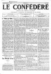
Fig.
cases of hard hot starting.
I
J-5923, Corburetor Holding Stond
Modificotion
MODIFICATION OF CARBURETOR
HOTDING STAND T.5923
Englne Stotling Aher Fast Stop
("Dual 4-Jet Carburetor Changes", March, 1956)
Engineering tests have shown that engine stalling
after a fast stop can be alleviated byremoving the air
horn assemblies from both carburetors and drilling
out one internal vent in each side with a 1,/8" drill.
The new 195? Rochester two-barrel carburetors
have a different throttle body. The carburetor
holding stand J-5923 must be modified to accommodate usage on off the car repairs.
wiII
It is important that only the two vents illustrated in
The holding stand can be used satisfactorily if
the t'March Nenrs" be drilled, otherwise excessive it is modified according to the dimensions shown in
fuel spilling may result if car is used for racing. Fig. 1. Two new 1,/4" holes must be drilled and
This condition has been corrected in production. tapped with a 5/16"-tB tap in the location as shoun.
5og on
Accelerotion
15 tB. RADIATOR CAP USED lN
T957 AIR. CONDITIONED CARS
(Not Previously Published)
A
new accelerating pump plunger and rod assembly, part number 7010846 has been released for
use on Extra Horsepower Engine carburetors. This
assembly replaces part number 7009129 currently
being used. Its purpose ls to correct complaints of
a sag in acceleration from a standing start by reducing the inttial discharge of fuel from the accelerating pump system'
DELco DEtuxE RADto
AII 195? air conditioned equipped cars wiII use
15 Ib. radiator pressure caps instead of the 13 Ib.
cap used on all other models. This part can be or-
dered under part number 861042.
1957 ENGINE IDLE S'EED
ADJUSTMENT
The hot engine idle speed on 1g5? Hydra-Matic
equipped cars should be set with the transmission in
Drive range. The idle speed specifications are as
follows:
ctRcutr
Idle speed in Drive
Delco Deluxe Radio 988623, released for Iate
1956 production, utilizes printed circuits. Radios
containing this circuit started with seriai N;*b;;
"oN-2". The last serial Number or tn"-*i"e-coinection model 988568 was "LN 2897".
AII Hydra-Matic Except
Air conditioning
430
All Air Conditioning
Dealerships who do radio work should make a
special point of checking the serial numbers to ascertain whether or not the radio has the printed circuit. If it does, the United Motor Service Manual
should be consulted for proper testing procedures.
56
NOTE: Idle
-
450 RPM
b00 _ bzo RpM
speed should be set on
Air Conditioning off.
Air
Con-
ditioned Cars with
Synchro-Mesh transmission equipped cars will
continue to be adjusted 450
-
470 RPM.
www.PontiacSafari.com
SERVICE CRAFTSMAN NEWS
Fig.
2
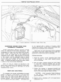
Correct lnsiollotion of Windshield Wosher Outlet
to be
WINDSHIELD WASHER OUTTET HOSE
I
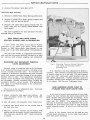
a mixture of lacquer, which
interior colors, and an anti-scuff com-
sprayed with
matches the
NCORR.ECTTY CONNECTED
Hose
pound to give maximum wear resistance.
Product Information Reports received recently
advise of ruptured vacuum pump diaphragms. Our
investigation of these cars has shown that the windshield washer outlet hose has been connected in
error to the air intake pipe on the bottom of the
windshield wiper motor. When the hose is connected
in this manner and the windshield wiper is turned
on, the water in the washer bottle is drawn into the
engine combustion chamber by way of the vacuum
pump. In passing through the pump the water causes
a rupture of the vacuum pump diaphragm.
Right hand and left hand panels will be packaged
individually along with h bottle of the anti-scuff compouad and an instruction sheet for painting.
Painling ,nslructions
1. Wash the surface of the unpainted panel with
white gasoline or some other suitable solvent
prior to painting.
2. Mix the entire contents of the one ounce bottl.e
of anti-scuff compound (565974) with one-half
pint (8 fl. oz.) of uncut lacquer of desired color.
Hose "A" (Fig. 2) should be attached to the
spray nozzle connection on the underside of the hood.
Do not connect it to the air inlet pipe, "Br', on the
windshield wiper motor.
(Mix thoroughly).
3. Reduce this mixture to spraying viscosity and
spray panel with three separate coats allowing
each to dry long enough for proper flowout.
FRONT SEAT SIDE PANETS
CAUTION: Avoid excessive finish thickness
as this tends to change the appearance of the
To eliminate the storage and handling of a great
number of different colored plastic Front Seat Side
Panels, all 195? model service panels will be released minus the silicon finish which was used on
previous models. This will provide a surface which
can be painted with Duco lacquer. The panels are
grain of the panel.
4. AIIow to dry a minimum of 6 to
installing in car.
51
8 hours before
www.PontiacSafari.com
SERVICE CRAFTSMAN NEWS
TWO TYPES OF TWO-TONING USED IN I957
Pontiac will make available two styles of twotoning for 195? models. These combinations will be
called "Starlight" and "Accent".
The Starlight Two-Tone combination will have
Body Area of one color with the Upper
Body Area and Insert of the other color. The Accent
Two-Tone combination will have the Lower and
Upper Body Areas of one color with the insert the
other color.
the Lower
Three code letters will designate the two-tone
combinations and the paint colors to be used. The
first letter signifies the color of the lower body, the
second letter signifies the color of the roof, and the
third letter signifies the color of the insert.
Two
examples of the coding appear below:
1. Starlight
-
AUU wiII mean Raven Black lower
and Sage Blue upper with Sage BIue insert.
2. Accent - AAU will mean Raven Black lower
upper body, with Sage Blue insert.
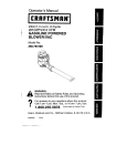
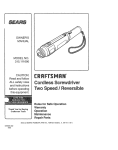
Fig.
3
Solid Color will be designated by use of a triple
letter combination. For example, AAA wiII mean
J-6116, Clutch Unit Holding Fixfure
Modificotion
a solid Raven Black.
filoDtFtcATroN oF ctulcH uNlT
HOTDING FIXTURE
and
Pontiac does not furnish a three-tone paint combination.
J-6II6
The gear ratio of the 195? ftrato-Flight reverse
unit has been decreased, resulting in a larger reverse sun gear. The larger sun gear will not fit
NEW CONTROT VALVE ASSEIVIBTY
rmPRovEs 2-3 sHrFT
through the Clutch Unit Holding Fixture J-6116 when
mounting the clutch unit in the fixture for disassembly
Beginning
or assembly.
with production transmission P56-
199036, a new control valve assembly provides lower
2-3 and 3-4 shift speeds and improved 2-3 shift feel.
To enable proper mounting of the unit, it is recthat the hole in the Holdlng Fixture be
enlarged by filing or grinding approximately t/16",
as indicated in Fig. 3.
The changes were made by recalibrating several
springs in the clutch and shift valve bodies and by
removing the l/8" check ball at the transition valve.
ommended
A service kit, part number 8616966, is available
making this modification in the field. The kit
consists of a new 2-3 shift valve outer spring, a new
3-4 shift valve inner spring and a new transition
valve spring. In addition to changing these springs
when modifying valve bodies in the field, the transitlon valve check ball (l/8") and the 3-4 shiftvalve
for
USE CORRECT TRIM CE'YIENT
TO PREVENT "BLEEDING''
To prevent "Bleeding" of trim attaching cement
through imitation leather and genuine Ieather upholstery, it is necessary to follow these directions:
outer spring should be removed and discarded.
1. 3M (Minnesota Mining and Manufacturing) Super
Weatherstrip Adhesive (Neoprene), or its equivaIent, should be used when attaching aII Ieather or
The field modification can be summarized
as
follows:
imitation leather trim.
2. 3M Trim Cement, or its equivalent, should be
used on all Cloth Trim. (This is the cement
that was previously recommended for use on all
trim.)
Clutch Yolve Body Assembly
1. Remove Transition Valve Spring (black) and replace with new spring (gray).
58
www.PontiacSafari.com
SERVICE CRAFTSMAN NEWS
2.
Remove Transition Check BaII (1/8").
Shifi Valve Body Assembly
t. Remove 3-4 Shift Valve Outer Spring anddiscard.
3-4 ShiJt Valve Ianer Spring (copper) and
replace with new spring (black).
2. Remove
3.
Remove 2-3 Shift Valve Spring (black) and replace with new 2-3 spring (black-daubed with
white paint).
The time allowance for this operation wiII be a
straight time of 1.6 hours.
NEW FRONT UNIT DRIVE TORUS
SPACING WASHER USED IN PRODUCTION
A new Front Unit Drive Torus Spacer Washer
(referred to as Front Unit Drive Torus Thrust
Washer in 1956 Hydra-Matic Shop Manual) is now
being used in all 1956 Hydra-Matic Transmissions.
The early type washer is completelyinterchangeable with the new washer and will continue to be used
for service until present supplies are exhausted.
ROCHESTER.
4GC SECONDARY THROTTTE
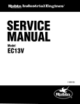
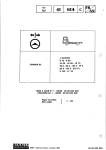
Fi9. 4 Meosuring Cleoronce Befween
VATVE ADJUSTMENT
Several cases of rough hot idle on the Rochester
4 GC carburetor have been traced to a sticking action
of the secondary throttle valve. To eliminate this
condition a carburetor adjustment has been released
which will ensure a positive closing of the secondary
throttle valve on idle. This adjustment establishes
tension of the secondary lock spring (Fig. a) against
the secondary throttle operating lever, holding the
secondary throttle valves closed. The adjustment
wiII apply to all 1956 Rochester 4 GC carburetors
as outlined below.
It is important that this adjustment be made accurately. .042" clearance ensures the proper amount
of tension when car is on hot idle. Too much tension
(less than .042" cLearance) could interfere with the
idle speed adjustment. Another possible cause for
secondary throttle valve sticking was covered onpage
48 of August, 1956 Service CraJtsman News.
NEW NEOPRENE WATER PUMP TO
CYTINDER HEAD INTET ELBOW HOSE
This is an on the car adjustment only. Following
is the adjustment procedure:
In all cases of power steering pump oil seal leak,
inspect the hose between the water pump and the left
hand cylinder head inlet elbow for oil damage. If the
hose is damaged, replace with the new neoprene
hose, part No. 524631. The neoprene hose is impervious to hydraulic fluid and therefore will not be
damaged by fluid which may spill or leak from the
1. Adjust carburetor idle speed and mixture. (Be
sure secondary valves are closed during this
adjustment.)
2. Shut off engine and manually close
choke valve.
3. Position idle speed screw on the second step of
the fast idle cam.
power steering pump. It will
fit all
1955 and 1956
cars.
4. Measure clearance between the secondary lock
spring and the secondary throttle operatinglever.
This clearance should be .042". Bend Iock spring
to
Secondory
Lock Spring ond Secondory Throitle
Operoting Lever
Stock of the former hose can be used on cars
without power steering or on the right hand side of
cars with power steering.
adjust.
59
www.PontiacSafari.com
SERVICE CRAFTSMAN NEWS
HIGH.POINT
ON UPPER END
'YIAR.K SHAFT
OF STEERING
On early 1957 Power Steering equipped cars, a
few units were used having the high-point mark on
the upper end of the steering shaft located toward
the bottom rather than at the top when the steering
is at the high-point (front wheels in the straight ahead ,
position).
If it is necessary to locate the high-point it must
be determined by disconnectingthe steering connecting
rod and measuring "Ioad" through the high-point with
a spring scale. The Iocation of the high-pointcanalso
be checked by tu-rning the steering wheel to its mid
position by corurting the turns from stop to stop.
FITTING HAR'VIONIC BATANCER ON CARS
EGIUIPPED WITH AIR. CONDITIONING
Fig.
Whenever it is necessary to replace the harmonic
balancer and,/ot key as a result of damage at the key
or harmonic balancer keyway, the following procedure should be used:
1. Measure the thickness of the new key with a
micrometer. If the key measures on the low
limit (.187") then use a piece of shlm stockto
bnild the key thickness up to .1885" or to permit
a slip fit in the keyway of the harmonic balancer.
2.
3.
Add
or
slip fit.
If
Dip Stick lnstolled
DIP STICK MODIFICATION FOR I956
AIR. CONDITIONED CARS
Reports have been received of interference between the air conditioning compressor hoses and the
crankcase oil level indicator when the indicator is
removed to check engine oil level. Continual removal
and replacement of the oil level indicator will eventually break the indicator.
On cars where this condition has occurred the
delete shims as necessary to provid! a
oil level indicator
tube assembly may be modified as
follows to permit easy removal of the indicator.
is such that it does not
(.003" Min.) into the keyway
of the harmonic balancer without the use of
shims, then carefully file the keyway in the
balancer (file both sides of the keyway) to
provide a slip fit of the balancer onto the
crankshaft and key. CAUTION: DO NOT FILE
THE KEY. Since the key must fit in the crankshaft, filing the key would provide too loose a
fit in the crankshaft.
NOTE: Before attemptigg any repair or fit of
the key to the harmonic balancer keyway, be sure
the key in the crankshaft is properly positioned.
the thickness of the key
provide
5
1. Procure a piece of sheet metzL l/32" thick,
l-7/8" Iong, and 5/8" wide.
2. Drill two 3/8" holes 1 l/2" apart.
3. Remove oil level indicator upper fube assembly
from engine, attach extension to upper tube assembly with a nut, lock washer, and bolt and
replace upper tube assembly and extension.
NOTE: This extension may be brazed on to
the upper tube assembly extension rather than
attaching with a bolt, lock washer, and nut.
4. Replace oil level indicator upper tube assembly.
a slit fit
SERVICE MANAGER-IMPORTANT
This News contqins importont service informotion on Pontioc cors. Eoch subiect should
be cross-referenced in the spoce provided ot the end of eoch section in the Shop Monuol
or its Supplement. Be sure o,nd cover every poinl wilh your enlire orgdnizolion,
Eoch service mon should sign in the spoce below ofter
he hos reod ond understonds the informotion in this issue.
60