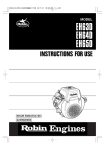
1
EH72D
LPG / NATURAL GAS Fueled Engine
2ZZ9020143
北米
(California Preposition 65)
!
▲
WARNING:
!
▲
The engine exhaust from this product contains
chemicals known to the State of California to
cause cancer, birth defects or other reproductive
harm.
(California only)
AIR INDEX
To show compliance with California emission regulations, a hangtag has been provided
displaying the Air Index level and durability period of this engine.
The Air Index level defines how clean an engine’s exhaust is over a period of time. A bar
graph scaled from “0” (most clean) to “10” (least clean) is used to show an engine’s Air Index
level. A lower Air Index level represents cleaner exhaust from an engine.
The period of time (in hours) that the Air Index level is measured is known as the durability
period. Depending on the size of the engine, a selection of time periods can be used to
measure the Air Index level (see below).
Descriptive Term
Applicable to Emissions Durability Period
Moderate
50 hours (engine from 0 to 80 cc)
125 hours (engine greater than 80 cc)
Intermediate
125 hours (engine from 0 to 80 cc)
250 hours (engine greater than 80 cc)
Extended
300 hours (engine from 0 to 80 cc)
500 hours (engine greater than 80 cc)
Notice: This hangtag must remain on this engine or piece of equipment, and only be
removed by the ultimate purchaser before operation.
Notice : FEDERAL EMISSION COMPONENT DEFECT WARRANTY and CALIFORNIA EMISSION CONTROL
WARRANTY are applicable to only those engines / generators complied with EPA (Environmental
Protection Agency) and CARB (California Air Resources Board) emission regulations in the U.S.A.
Notice : To the engines/generators exported to and used in the countries other than the U.S.A., warranty
service shall be performed by the distributor in each country in accordance with the standard Subaru
engine/generator warranty policy as applicable.
WA2626
FEDERAL EMISSIONS COMPONENT DEFECT WARRANTY
EMISSIONS COMPONENT DEFECT WARRANTY COVERAGE - This emission warranty is applicable in all States, except the
state of California.
Fuji Heavy industries Ltd. and Robin America, Inc., Lake Zurich, Illinois, (herin “ROBIN AMERICA”) warrant(s) to the initial retail
purchaser and each subsequent owner, that this Nonroad engine (herein “engine”) has been designed, and equipped to conform at
the time of initial sale to all applicable regulations of the U.S.
Environmental Protection Agency (EPA), and that the engine is free of defects in material and workmanship which would cause this
engine to fail to conform with EPA regulations during its warranty period.
For the components listed under PARTS COVERED, the service dealer authorized by ROBIN AMERICA will, at no cost to you, make
the necessary diagnosis, repair, or replacement necessary to ensure that the engine complies with applicable U.S. EPA regulations.
EMISSION COMPONENT DEFECT WARRANTY
PERIOD
*Any non-authorized replacement part, or malfunction of
authorized parts due to use of non-authorized parts.
The warranty period for this engine begins on the date of
sale to the initial purchaser and continues for a period of
two years.
PARTS COVERED
OWNER’S WARRANTY RESPONSIBILITIES
As the engine owner, you are responsible for the performance of the required maintenance listed in your owner’s
manual. ROBIN AMERICA recommends that you retain
all receipts covering maintenance on your engine, but
ROBIN AMERICA cannot deny warranty solely for the
lack of receipts or for your failure to ensure the performance of all scheduled maintenance.
As the engine owner, you should however be aware that
ROBIN AMERICA may deny warranty coverage if your
engine or part has failed due to abuse, neglect, improper
maintenance or unapproved modifications.
You are responsible for presenting your engine to the
nearest service dealer authorized by ROBIN AMERICA
when a problem exists.
If you have any questions regarding your warranty
rights and responsibilities, you should contact the Robin
America customer service department at 1-800-277-6246
for the information.
Listed blow are the parts covered by the Emission Components Defect Warranty. Some of the parts listed below
may require scheduled maintenance and are warranted
up to the first scheduled replacement point for that part.
EXHAUST EMISSIONS
(1) Fuel Metering System
(i) Carburetor and internal parts (and/or pressure regulator or fuel injection system.)
(ii) Air/fuel ratio feedback and control system, if
applicable.
(iii) Cold start enrichment system, if applicable.
(iv) Regulator assy (gaseous fuel, if applicable).
(2) Air Induction System
(i) Intake manifold, if applicable
(ii) Air filter
(3) Ignition System
(i) Spark Plugs
(ii) Magneto or electronic ignition system.
(iii) Spark advance/retard system, if applicable.
(4) Exhaust manifold, if applicable
(5) Miscellaneous Items Used in Above Systems
(i) Electronic controls, if applicable
(ii) Hoses, belts, connectors, and assemblies.
(iii) Filter lock assy (gaseous fuel, if applicable).
*EVAPORATIVE EMISSIONS
(1) Fuel Line
(2) Fuel Line Fittings
(3) Clamps
*Fuji is not liable for the warranty on these parts if these
parts are installed on the engine by the equipment manufacturer. Please refer to the equipment manufactures
warranty.
OBTAINING WARRANTY SERVICE
To obtain warranty service, take your engine to the nearest authorized Robin America service dealer. Bring your
sales receipts indicating date of purchase for this engine.
The service dealer authorized by ROBIN AMERICA will
perform the necessary repairs or adjustments within a
reasonable amount of time and furnish you with a copy of
the repair order. All arts and accessories replaced under
this warranty become the property of ROBIN AMERICA.
WHAT IS NOT COVERED
*Conditions resulting from tampering, misuse, improper
adjustment (unless they were made by the service
dealer authorized by ROBIN AMERICA during a warranty
repair), alteration, accident, failure to use the recommended fuel and oil, or not performing required maintenance services.
*The replacement parts used for required maintenance
services.
*Consequential damages such as loss of time, inconvenience, loss of use of the engine or equipment, etc.
*Diagnosis and inspection charges that do not result in
warranty-eligible service being performed.
THINGS YOU SHOULD KNOW ABOUT THE
EMISSION CONTROL SYSTEM WARRANTY
MAINTENANCE AND REPAIRS
You are responsible for the proper maintenance of the
engine. You should keep all receipts and maintenance
records covering the performance of regular maintenance in the event questions arise. These receipts and
maintenance records should be transferred to each subsequent owner of the engine. ROBIN AMERICA reserves
the right to deny warranty coverage if the engine has not
been properly maintained. Warranty claims will not be
denied, however, solely because of the lack of required
maintenance or failure to keep maintenance records.
MAINTENANCE, REPLACEMENT OR REPAIR OF
EMISSION CONTROL DEVICES AND SYSTEMS MAY
BE PERFORMED BY ANY REPAIR ESTABLISHMENT
OR INDIVIDUAL;
HOWEVER, WARRANTY REPAIRS MUST BE PERFORMED BY A SERVICE DEALER AUTHORIZED BY
ROBIN AMERICA. THE USE OF PARTS THAT ARE
NOT EQUIVALENT IN PERFORMANCE AND DURABILITY TO AUTHORIZED PARTS MAY IMPAIR THE
EFFECTIVENESS OF THE EMISSION CONTROL SYSTEM AND MAY HAVE A BEARING ON THE OUTCOME
OF A WARRANTY CLAIM.
If other than the parts authorized by ROBIN AMERICA
are used for maintenance replacements or for the repair
of components affecting emission control, you should
assure yourself that such parts are warranted by their
manufacturer to be equivalent to the parts authorized by
ROBIN AMERICA in their performance and durability.
HOW TO MAKE A CLAIM
All repair qualifying under this limited warranty must be
performed by a service dealer authorized by ROBIN
AMERICA. In the event that any emission-related part
is found to be defective during the warranty period, you
shall notify Robin America customer service department
at 1-800-277-6246 and you will be advised of the appropriate warranty service dealer or service providers where
the warranty repair can be performed.
WS6645
FOREWORD
Thank you very much for purchasing a ROBIN ENGINE.
Engine serial No.
Your SUBARU ENGINE can supply the power to operate various sorts of machines and equipment.
Please take a moment to familiarize yourself with the proper operation and maintenance procedures in
order to maximize the safe and efficient use of this product.
Due to constant efforts to improve our products, certain procedures and specifications are subjected to
change without notice.
When ordering spare parts, always give us the MODEL, SPECIFICATION and SERIAL NUMBER of your
engine.
Please fill in the following blanks after checking the specification number on your engine.
SPEC NO.
EH
SERIAL NO.
For your nearest SUBARU distributor (and/or dealer), you are able to check at our SUBARU website of
the following URL;
http://www.subarupower.com
CONTENTS
SAFETY PRECAUTIONS ........................................................................................................................... 1
COMPONENTS ........................................................................................................................................... 4
PRE-OPERATION CHECKS....................................................................................................................... 5
BATTERY INSTALLATION ......................................................................................................................... 7
OPERATING YOUR ENGINE ..................................................................................................................... 9
EASY TROUBLESHOOTING ................................................................................................................... 10
MAINTENANCE SCHEDULE ................................................................................................................... 12
“HOW-TO” MAINTENANCE .................................................................................................................... 14
PREPARATIONS FOR STORAGE ........................................................................................................... 17
SPECIFICATIONS..................................................................................................................................... 18
SYMBOLS
Read the owner’s manual
Stay clear of the hot surface
Exhaust gas is poisonous.
Do not operate in an unventilated area.
Stop the engine before refueling
Fire, open flame and smoking prohibited
Fire
Explosion
Explosive Pressure
On (Run)
Plus ;
positive polarity
Off (Stop)
Battery
Engine oil
Engine start
(Electric start)
Add oil
6
SAFETY PRECAUTIONS
! ) is used with a signal
The safety alert symbol (▲
word (DANGER, CAUTION, WARNING), a pictorial
and/or a safety message to alert you to hazards.
DANGER indicates a hazard which, if not avoided,
will result in death or serious injury. WARNING indicates a hazard which, if not avoided, could result
in death or serious injury. CAUTION indicates a
hazard which, if not avoided, might result in minor
or moderate injury. NOTICE indicates a situation
that could result in engine damage. Follow safety
messages to avoid or reduce the risk of injury or
death.
! WARNING
▲
Propane and Natural Gas are
extremely flammable and explosive.
Fire or explosion can cause
severe burns or death.
• Install the fuel supply system according to
applicable fuel-gas codes.
• Before placing the engine into service, the fuel
system lines must be properly purged and leak
tested. Procedures used in gaseous fuel leakage tests must comply strictly with applicable
fuel gas codes.
• DO NOT use flame or any source of heat to test
for gas leaks.
• NO leakage is permitted.
• LP gas is heavier than air and will settle in low
areas.
• Natural gas is lighter than air and will collect in
high areas.
• DO NOT operate engine if smell of fuel is
present or other explosive conditions exist.
• The slightest spark can ignite these fuels and
cause an explosion.
• DO NOT smoke around the engine. Wipe up
any oil spills immediately. Keep the area near
the engine clean and free of debris.
The manufacturer cannot possibly anticipate every
possible circumstance that might involve a hazard.
The warnings in this manual, and the tags and
decals affixed to the unit are, therefore, not allinclusive. If you use a procedure, work method or
operating technique that the manufacturer does not
specifically recommend you must satisfy yourself
that it is safe for you and others. You must also
make sure that the procedure, work method or operating technique that you choose does not render
the engine system unsafe.
! WARNING
▲
Running engine gives off carbon
monoxide, and odorless, colorless,
poison gas.
Breathing carbon monoxide can
cause headache, fatigue, dizziness, vomiting, confusion, seizures, nausea, fainting or death.
• Operate engine ONLY outdoors.
• Keep exhaust gas from entering a confined
area through windows, doors, ventilation
intakes, or other openings.
7
SAFETY PRECAUTIONS
Please make sure you review each precaution carefully.
EXHAUST PRECAUTIONS
• Never inhale gas.
It contains carbon monoxide, a colorless,
orderless and extremely dangerous gas
which can cause unconsciousness
or death.
• Never operate the engine indoors or in
a poorly ventilated area, such as tunnel,
cave, etc.
• Exercise extreme care when operating
the engine near people or animals.
• Keep the exhaust pipe free of foreign
objects.
REFUELING PRECAUTIONS
• Be sure to stop the engine prior to connecting a fuel line. Refuel outdoors, in a
well-ventilated area.
• Use only approved LP/NG fuel hose and connectors.
• Check for fuel leaks before operating the engine.
FIRE PREVENTION
• LPG is extremely flammable and combustible, and so is NATURAL gas.
• Do not operate while smoking or near an open flame.
• Do not use around dry brush, twigs, cloth rags, or other flammable materials.
• Keep the engine at least 3 feet (1 meter)
away from buildings or other structures.
• Keep the engine away from flammables
and other hazardous material (trash, rags,
lubricants, explosives).
• DO not leave cigarettes, sparks and
flames near by any fuel-related parts.
• Never smoke near LPG or Natural gas
and keep other flames and sparks away.
• In order to reduce the risk of the fire or
explosion, be careful when working
around LPG or Natural gas.
8
PROTECTIVE COVER
• Place the protective covers over the
rotating parts.
If rotating parts such as the drive shaft,
pulley, belt, etc. are left exposed, they
are potentially hazardous.
To prevent injury, equip them with
protective covers or shrouds.
• Be careful of hot parts.
The muffler and other engine parts
become very hot while the engine is
running or just after it has stopped.
Operate the engine in a safe area and
keep children away from the running
engine.
• Never make adjustments on the
machinery while it is connected to the
engine, without first removing the ignition
cable from the spark plug. Turning the
crankshaft by hand during adjusting
or cleaning might start the engine, and the
machinery with it, causing serious injury to
the operator.
• Never run the engine with governor
disconnected, or operate at speeds in
excess of 3600 rpm load.
SURROUNDINGS
• Operate the engine on a stable, level
surface free of small rocks, loose gravel,
etc.
NOTE
Operating the engine at a steep
incline may cause seizure due to
improper lubrication even with a
maximum oil level.
9
• Disconnect the LP/NG fuel line before
transporting the engine.
• Do not move the engine while in
operation when it has been removed from
the equipment.
• Keep the unit dry (do not operate it in rainy
conditions).
PRE-OPERATION CHECKS
• Carefully check fuel hoses and connections for looseness and LPG or Natural Gas
leakage. Leaking fuel creates a potentially
dangerous situation.
• Check bolts and nuts for looseness.
A loose bolt or nut may cause serious
engine trouble.
• Check the engine oil daily and refill if
necessary.
• Check the fuel level and refill if necessary.
• Wear snug fitting working clothes when
operating the engine. Loose aprons,
towels, belt, etc., may be caught in the
engine or drive train, causing a dangerous
situation.
10
COMPONENTS
Hook
Air cleaner cover
Regulator
Blower housing
Oil Cooler
Mixer
Oil filler cap
Spark plug cap
Governor lever
Voltage regulator
Oil filter
Oil gauge
PTO shaft
Electric starter
Oil drain plug
(on both sides)
REMARKS:
• Fuel tank, valve, (sediment bowl type is recommended), fuel hoses, and fuel filter are
required for connecting fuel source to this engine.
• A battery rated at 12V-36AH or larger with the specified cable are required for electric starter
operation. Make the proper electrical wiring arrangements before normal engine operation.
(See “Battery Installation” for detailed information and data.)
11
PRE-OPERATION CHECKS
ENGINE OIL (CHECK DAILY)
Before checking or refilling engine oil, be
sure the engine is not running and is
located on a stable, level surface.
• If the oil level is below the lower level line
on the oil gauge, refill with the proper oil
(see table) to the upper level.
OIL CAPACITY : 1.55 liter (1.64 qt.)
Oil gauge
Upper level
Lower level
Oil
gauge
Oil
gauge
Upper
level
Upper
level
Lower
level
Lower
level
• When filling oil in the engine, keep the
engine level and fill the oil up to the
upper mark of the oil gauge. Measure the
oil level with the oil gauge plugged in
position .
• After an oil change, run the engine,
and recheck the oil level. The oil level
may drop a little as the oil fills the oil
filter. Fill the oil up to the upper mark
of the oil gauge.
• Change oil if it is contaminated.
(See “Maintenance Schedule”)
• Use 4-stroke automotive detergent oil
of API service class SE or higher grade
(SG, SH or SJ is recommended).
• If multi-grade oil is used, oil consumption
tends to increase when the ambient
temperature is high.
5W
10W
20W
Single
grade
#20
#30
#40
10W-30
Multi
grade
Ambient
temperature
10W-40
-20
-10
0
10
20
30
40
-4
14
32
50
68
86
104
12
GASEOUS FUEL
! WARNING
▲
Do not refuel while smoking, near an open flame or other potential hazards.
Fuel Recommendations
LPG
Propane content of 95% of higher
NATURAL GAS
Methane content of 90% or equivalent
INSTRUCTIONS FOR
CONVERTING TO NATURAL GAS
OPERATION
The engine is optimized for LP operation from the
factory. The steps below show how to remove the
orifice for NATURAL GAS operation.
1. Remove Air Cleaner Assembly
2. Loosen fuel hose clamp and remove the 1”
black fuel hose from the front of the carburetor
3. Remove threaded brass orifice with either flat
head screw driver or pliers
4. Replace fuel line hose and tighten clamp
5. Replace Air Cleaner Assembly
6. Check for leaks using the procedure below.
LEAK TESTING THE FUEL
SYSTEM
1. Create a mixture of 50% water and 50% liquid
dishwashing soap.
2. Turn ON the fuel supply by turning the LP
fuel tank shut off calve on full turn COUNTERCLOCKWISE.
3. Using a sponge, rag or small non-metallic
brush, apply the soap water mixture at each of
the connection locations of the fuel piping
system.
4. Check each location for growing bubbles,
which indicates a fuel leak.
5. Close the LP fuel shut off valve.
6. Tighten or replace any leaking conncections.
13
VAPOR WITHDRAWL
With a vapor withdrawal system, the LP fuel is vaporized in the fuel tank by heat input from the
ambient temperature. The pressure is reduced to about 11” water column (0.4psi) on the outlet
side of the primary regulator. The vaporized fuel is then brought to the engine and demand regulator on the engine reduces the pressure even further before it engine the carburetor (mixer).
Approximately 10 to 20% of the tank capacity is needed for fuel expansion from the liquid to the
vapor state. The user should be aware that when the ambient temperatures are low and engine
fuel consumption is high, the vapor withdrawal system may not function efficiently. Ambient temperature around the supply tank must be high enough to sustain adequate vaporization for the
system or it will not deliver the needed fuel volume.
LPG PIPING DIAGRAM
(Not Supplied)
NATURAL GAS PIPING DIAGRAM
(Not Supplied)
14
BATTERY INSTALLATION
For electric starter operation, proper electric wiring arrangements are needed before normal
engine operation.
PARTS NEEDED
• Use a battery rated 12V-36AH or larger.
• Use a proper cable and ground wire to
connect battery and key switch and electric
starter.
PARTS NEEDED
CABLE
DIA.
Less than
1.5m
WIRE GAUGE
AWG (BS)
BWG
SAE
JIS
7.3mm
1
6
AV15
1.5m to
2.5m
8.5mm
0
4
AV20
2.5 m to
4.0m
10.8mm
3/0
2
AV30
EARTH (GROUND) WIRE, use a flat braided
wire of 0.03 sq. in. or larger sectional area.
(SAE GAUGE 4)
CABLE
LA406
CABLE
LENGTH
LA408
KEY SWITCH CABLE
EARTH (GROUND) WIRE
25mm
15
CABLE
LENGTH
CABLE
DIA.
Less than
1.5m
WIRE GAUGE
AWG (BS)
BWG
SAE
JIS
1.5mm
14
16
AV1.25
1.5m to
3.0m
1.9mm
120
14
AV2
3.0 m to
5.0m
2.4mm
10
13
AV3
WIRING
• Connect positive terminal of electric starter
and positive terminal of the battery with
battery cable.
• Ground negative terminal of the battery to
the body of engine or machine with ground
wire.
Cable
+
Battery
-
NOTE
Tighten bolts and nuts on terminals
securely so they will not be loosened
by vibration.
Electric starter
terminal
Earth wire
WIRING DIAGRAM
Optional hardware shown by dotted lines. Select wire of proper gauge and connect battery as
shown by the dotted line in the wiring diagram.
16
OPERATING YOUR ENGINE
STOPPING
STARTING
ELECTRIC STARTER
FUEL VALVE
1
1
(Provided by the equipment manufacturer)
Open the fuel valve.
Turn the key switch to the “STOP”
position.
ELECTRIC STARTER
2
FUEL VALVE
2
(Provided by the equipment manufacturer)
Turn the key swtich to the “START”
position.
• Do not operate the electric starter
continuously for more than 5
seconds, even if the engine does
not start.
• If the engine failed to start, set the
key to the “RUN” position and wait
for about 10 seconds before
retrying.
• Never turn the key switch to the
“START” position while engine is
running.
Close the fuel valve.
17
EASY TROUBLESHOOTING
Perform the following checks before you take the engine to your Subaru dealer.
If you still have trouble after completing the checks, take the engine to your nearest Subaru
dealer.
Checking Items
Possible Cause
Correction
Battery discharged
Recharge battery
• Fuel valve CLOSED
or OFF (if equipped)
Move fuel valve to OPEN or
ON
• Engine switch OFF
Turn engine switch to ON
Check battery
Out of fuel
Refuel
Remove and inspect spark
plugs
Spark plugs faulty, fouled, or
improperly gapped
Clean, gap or replace spark
plugs
Filter element clogged
Clean or replace filter element
• Engine will not start
Check battery
Check control position
(Power equipment side)
• Engine lacks power
Check air cleaner
Is ther enough compression?
If the spark plug is loose, tighten it.
18
Is there a strong spark across the
electrode?
! WARNING
▲
Wipe off spilled fuel carefully before
checking the spark plug. Place
spark plug as far away from spark
plug hole as possilbe. Do not hold
spark plug by hand while checking.
1. Remove the spark plug and connect it to the
plug cap.
Turn key switch to START position while
grounding the spark plug against engine
body.
2. Try with a new spark plug if the spark is
weak or there is no spark.
3. The ignition system is faulty if there is no
spark with a new spark plug. Take your
engine to your nearest Subaru dealer.
Is your battery will charged?
Check the battery, it may be discharged and
unable to operate the electric starter.
Consult your nearest dealer or service shop.
19
EASY TROUBLESHOOTING
DAILY INSPECTION
Before funning the engine, check the following service items.
Enough Fuel
Excessive vibration, noise
Clean air cleaner element
Safe surroundings
Enough clean engine oil
Leakage of fuel and engine oil
Loose or broken bolt and nuts
PERIODIC MAINTENANCE
Periodic maintance is vital to safe and efficient operation of your engine. Check the table below
for periodic maintenance intervals.
20
(Periodic Maintenance Schedule Table)
Maintenance Items
Clean engine and check bolt and nuts
Check and refill engine oil
Change engine oil (*Note 1)
Replace engine oil filter (*Note 1)
Every 8 hours
(Daily)
Every
50
hours
Every
200
hours
Every
500
hours
Every
1000
hours
• (Daily)
• (Refill daily
to full level)
• (Initial 20 hours)
• (Initial 20 hours)
Check battery electrolyte fluid level
•
•
•
•
•
Clean spark plug
Clean air cleaner
Clean fuel strainer
•
•
•
Replace air cleaner element
Clean and adjust spark plug and electrodes
Clean mixer
•
•
•
•
•
•
Clean cylinder head
Clean engine base (oil pan)
Cleck and adjust valve seats
Check and adjust valve cleanance
Replace spark plug
Replace fuel and oil hose
•
*Note 1 : Initial oil change and oil filter replacement should be performed after 20 hours of
operation.
Thereafter change oil every 50-100 hours and replace oil filter 200 hours.
More frequent oil changing, oil filter replacement and air cleaner service on
replacement may be necessary depending on operation conditions.
This would include dusty environment, high ambient temperature, heavy engine
loading.
Before changing oil, check for a suitable way to dispose of old oil. Do not pour it down
into sewage drains, onto garden soil or into open streams. Your local zoning or
environmental regulations will give you more detailed instructions on proper disposal.
*Note 2 : As to the procedures, please refer to the Service Manual or consult your nearest
SUBARU service dealer.
21
“HOW-TO” MAINTENANCE
SPARK PLUG
• Clean and remove carbon deposits off
from the spark plug electrode, using a plug
cleaner or wire brush.
• Check if the electrode gap is in the proper
range.
Adjust gap to the specifications:
0.7mm to 0.8mm
• Use a specified spark plug:
BPR6ES (NGK)
0.7 to 0.8 mm
ENGINE OIL
• Initial oil change
.....After 20 hours of operation
• Thereafter
.....Every 50 to 100 hours of operation
Oil drain plug
(On both sides)
1. When changeing oil, stop the engine and
loosen the drain plug.
2. Re-install the drain plug before refilling oil.
3. Refer to the recommended oil table.
(See Pre-operation checks)
4. Always use the best grade and clean oil.
Contaminated oil, poor quality oil and
shortage of oil cause damage to engine or
shorten the engine life.
OIL CAPACITY : 1.55 liter (1.64 qt.)
22
ENGINE OIL FILTER
• Initial engine oil filter replacement should
be performed after 20 hours of operation.
Thereafter replace the engine oil filter every
200 hours.
• When installing a new oil filter, apply oil
to O-ring, attach the oil filter in position and
tighten 2/3 turns by hand or with wrench
after touching the O-ring to the sealing
surface of engine.
• Run the engine for a minute; stop the
engine and check for oil leakage around the
oil filter and recheck the oil level.
! CAUTION
▲
To prevent injury, pay attention
to the spilled hot engine oil when
replacing engine oil filter.
Knob
AIR CLEANER
Air cleaner cover
A dirty air cleaner element will cause starting
difficulty, power loss, engine malfunctions, and
shorten engine life extremely.
Always keep the air cleaner element clean.
Replace the air cleaner element more often in
dusty environments.
Grommet
Element
The air cleaner paper element can be removed after removing knob and air cleaner
cover.
When installing, set the paper element on the
air cleaner base.
Check if the grommet is in position, and then
install the cover with knob tightened securely.
Base
23
• Paper element
Clean by taping gently to remove dirt and blow off dust. Never use oil.
Clean or replace paper element every 50 hours of operation, and replace element set every
200 hours or once a year.
Clean and replace air cleaner elements more often when operation in dusty
environments.
BOLTS, NUTS AND SCREWS
Retighten loose bolts and nuts
Check for fuel and oil leaks
Replace damaged parts with new ones.
Keep safety in your mind.
FUEL AND OIL HOSE
! WARNING
▲
Take extreme caution when replacing fuel hose ; fuel is flammable.
Replace the fuel and oil hose every 1,000 hours or every year.
If fuel and oil hose leak is found, replace the fuel hose immediately.
BATTERY
! WARNING
▲
Battery electrolyte is an acid and is poisonous and corrosive.
Serious injury results from contact with the skin, eyes or clothing.
If the electrolyte fluid is below level line, refill battery with distilled water.
24
PREPARATIONS FOR STORAGE
ENGINE OIL
• Change the engine oil with fresh oil.
• Remove the spark plug, pour about 5cc of
engine oil into the cylinder, slowly start the
engine for 2 or 3 seconds, and re-install the
spark plug.
CLEAN AND STORE
• Remove the spark plug wires from the spark
plugs.
• Slowly turn the crankshaft until resistance is
felt and leave it in that position.
• Clean the engine thoroughly with an oiled
cloth, cover the engine, and store the
engine indoors in a well ventilated, low
humidity area.
25
SPECIFICATIONS
MODEL
EH72 LP/NG
Air-Cooled, 4-stroke, V-Twin Cylinder, Horizontal P.T.O. shaft,
OHV, LPG/NATURAL GAS Fueled Engine
Bore x Stroke
mm(in)
2-84 x 65 (3.31 x 2.56)
Displacement
cm³(cu.in)
720 (43.9)
Maximum Torque
N•m
39.5 N•m @ 2500rpm
LPG
(Propane content of 95% or higher) : 25hp18.6kw@3600rpm
Maximum Output
Natural Gas
(Methane content of 90% or equivalent) : 21hp15.7kw@3600rpm
Direction of Rotation
Counterclockwise as viewed from P.T.O. shaft side
Automotive Engine Oil SAE #20, #30 or 10W-30;
Lubricant
Class SE or higher (SG, SH or SJ is recommended)
Capacity of Lubricant
1.55 (52.48)
Fuel
LPG/NATURAL GAS
Spark Plug
BPR6ES (NGK)
Starting System
Electric Starter
Dry Weight
46 (101.3)
Dimension
317 x 477 x 475 (12.5 x 18.8 x 18.7)
(L x W x H)
kg (lb)
Valve Clearance
0.1 to 0.02mm (0.0039 to 0.0008 in)
(Intake & Exhaust)
Not: Adjust the valve clearance while the engine is cold.
Type
26
27
ISSUE EMD-EU2415