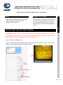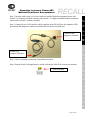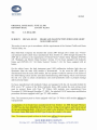
1
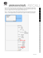
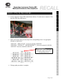
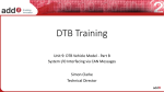
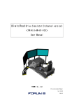
RECALL
Stoneridge Instrument Cluster ABS
Malfunction Indicator Noncompliance
CORRECTIVE ACTION_________----___
Under certain conditions the anti-lock brake
(ABS) malfunction indicator may not
illuminate when required.
Affected units will require corrective action
based on instrumentation software version
and ABS control module type. Complete
the appropriate corrective action procedure
below.
SOFTWARE UPDATE PROCEDURE
WARNING: Always follow all Federal, State, Local, and Shop safety standards and use proper
safety equipment when performing these procedures. NOTE: Software update procedure is NOT
applicable to buses with cab mounted “D” version ABS ECU’s.
Step 1. Set the bus parking brake.
Step 2. Using steering column stalk switch and instrument cluster diagnostics menu verify current
software version displayed under part number menu.
--R E C A L L
ISSUE________________________________
C A M P A I G N------R 1 1 S Z-
Models Affected: 2007-2011 Model Year “Vision” Buses
Page 1 of 8
Step 3. On units with version 1.4 or lower software installed flash the instrument cluster with
version 4.11 software provided. On units with version 1.5 or higher installed flash the instrument
cluster with version 4.1 software provided.
Connect to a
computer USB port
Step 5. Once everything is connected, turn ignition switch on.
Step 6. Run the Flash Tool application by double clicking the Flash Tool icon on your desktop.
R E C A L L
Icon on desktop
C A M P A I G N
-- R
Connect to bus
diagnostic connector
1
1
Step 4. Connect Kvaser CAN interface cables (supplied in kit 00114694) to the computers USB
port and the Bus diagnostic connector located below the driver side dash area.
Z ---
RECALL
S
Stoneridge Instrument Cluster ABS
Malfunction Indicator Noncompliance
Page 2 of 8
Stoneridge Instrument Cluster ABS
Malfunction Indicator Noncompliance
RECALL
C A M P A I G N
-- R
1
1
S
Z ---
Step 7. You will see the following screen (main window):
R E C A L L
Step 8. Click on “Open Hex File…” button
a. Select the appropriate software version hex file supplied.
Step 9. Click on “Flash!” button
a. A confirmation window will appear, click on “Flash!” button
Page 3 of 8
Step 10. Wait for the cluster unit to automatically restart. Once the flash process has started
there is no way to abort. The status screen will display “passed Operation successful!” when
process is complete. DO NOT switch ignition off while in process.
R E C A L L
C A M P A I G N
-- R
1
1
Step 11. Using steering column stalk switch and instrument cluster diagnostics menu verify
software version displayed under part number menu is updated version level you installed.
Z ---
RECALL
S
Stoneridge Instrument Cluster ABS
Malfunction Indicator Noncompliance
Page 4 of 8
R E C A L L
C A M P A I G N
-- R
1
1
Step 12. Using steering column stalk switch and instrument cluster configuration menu verify
the “ABS WL Source” is set for “J1939”. Access to the configuration option is protected and
requires the user to provide the access code via the “Password” option to enable it. Enter the
password “2290” first. It is necessary to execute an ignition cycle (OFF/ON), after revising
desired parameters, for EE parameter changes to take effect.
Z ---
RECALL
S
Stoneridge Instrument Cluster ABS
Malfunction Indicator Noncompliance
Step 13. Instrument cluster software update is complete.
Page 5 of 8
Thumb screws.
Cover is located
lower center of
dash.
ECU
Page 6 of 8
S
1
1
1. Park the bus on a level surface, apply parking brakes, turn off engine and remove keys.
Chock wheels.
2. Disconnect batteries – Note; When disconnecting the batteries, remove the negative
cable first.
3. Remove chassis Power Distribution Unit (PDU) cover by unscrewing two thumb
screws. The thumb screws are located at the top of each side of the cover.
-- R
WARNING: Always follow all Federal, State, And Local and Shop safety standards and use
proper safety equipment when performing these procedures. Observe all safety precautions to
secure the bus from rolling. NOTE: Wiring update procedure is ONLY applicable to buses
with cab mounted “D” version ABS ECU’s.
C A M P A I G N
WIRING UPDATE PROCEDURE__________________________
Z ---
RECALL
R E C A L L
Stoneridge Instrument Cluster ABS
Malfunction Indicator Noncompliance
WIRING UPDATE PROCEDURE__________________________
5. Splice each circuit from previous step to the corresponding circuit. Use appropriate
terminal as listed below.
“ABS LGT”, “ABS ACTIVE”, circuit use terminal # 00005840.
“ABS GND”, “ABS BATT”, “MOD PUMP BATT”, circuit use terminal # 0036508.
“ABS IGN” circuit use terminal # 00036507.
R E C A L L
Remove two “C504” connectors
and splice each circuit to the
corresponding circuit.
C A M P A I G N
-- R
1
1
4. Locate connector C504 in PDU (detail shown below). Cut and remove connector C504
from the PDU and ABS harness.
Z ---
RECALL
S
Stoneridge Instrument Cluster ABS
Malfunction Indicator Noncompliance
6. Wiring update procedure is complete.
Page 7 of 8
RECALL
8. Blink code 1-1 indicates system OK and no fault codes. Any other blink code indicates
a fault code. If any fault code exists please refer to maintenance manual 39 included in
your Vision service manual.
9. ABS wiring update procedure is complete.
PARTS
PART NUMBER
00036507
00036508
00005840
QUANTITY
1
3
2
DESCRIPTION
Terminal, Butt Conn, 14-16 GA, Sealed
Terminal, Butt Conn, 10-12 GA, Sealed
Terminal, Butt Conn, 18-22 GA, Sealed
Page 3 of 3
R E C A L L
Diagnostic Switch
located in this panel.
C A M P A I G N
--R
1
1
S Z -----
Stoneridge Instrument Cluster ABS
Malfunction Indicator Noncompliance