1
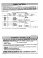
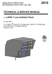
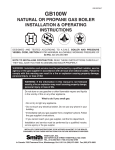
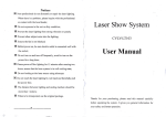
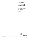
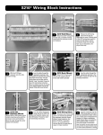
Honeywell
-
THE S89 AND S890 PROVIDE OPERATING CONTROLAND SYSTEM SHUTDOWN ON LOSS OF MAIN
BURNER FLAME IN DIRECT IGNITION CENTRAL
HEAT FURNACES
AND HEATING APPLIANCES
WITH HOT SURFACE IGNITER.
0 S89C,G,J and S890C,G,J
combination igniter-sensor.
are for systems
with a
0 S890D,H and S890D,H are for systems with separate
igniter and sensor.
0 S89C,D,J
ignition.
and S890C,D,J
lock out after one try for
0 S89G,H and S890G,H provide three tries for ignition
before lockout, with 30 sec. min. purge before second
and third tries.
0 S89J and S89OJ provide 2 or 4 sec. (depending
model) max. ignition activation periods.
on
q S890 provides 30 sec. min. prepurge on initial trial for
ignition.
0 Compatible with Norton 201 and 271 or equivalent
surface igniters.
0 S89D,H and S890D,H require a separate
mounted on burner (Q354 recommended).
hot
sensor
•i Available
with leadwires for line voltage connections.
0 Available
Damper.
with Molex plug for connecting
D80D Vent
Cl Modules can be used on either naturalor LP gas; they
provide 100 percent shutoff of gas on lockout.
0 Modules have relay contacts for use with any direct
ignition gas control with max. 2.0 A, 24 Vat rating.
0
Modules use rectification
principle for flame sensing.
0 Minus 40° F to +175”
temperature rating.
F [minus 40” C to +79” C]
J.A.
Form Number 68-6070-l
0 Honeywell
Inc. 1989
Rev. 9-89
rating. VR8205, VR845, VR854, VR8450 or VR8540
recommended.
HOT SURFACE IGNITER OR IGNITER-SENSOR:
Norton Model 201 or 271 or equivalent.
ELECTRICAL RATINGS:
Voltage and frequency: 20.5 to 28.5 V (24 V nom.), 60
HZ.
Current rating: 0.2 A.
Gas control contact ratings (at 24 Vat): 2.0 A running,
20.0 A inrush.
IGNITER WARM-UP PERIOD: 34 sec., nom.
THERMOSTAT ANTICIPATOR SETTING: 0.2 A plus oas
control current rating.
AMBIENT TEMPERATURE
RATING: Minus 40° F to
+175“ F [minus 40“ C to +79” C].
RELATIVE HUMIDITY RATING: 5 to 90 percent at 95“ F.
FLAME FAILURE RESPONSE TIME: 2 sec. max. with a
2.5 uA flame signal.
FLAME CURRENT: 0.8 J.LADC, min.
TERMINALS: 114 in. male quick connects for line voltage
and sensor connections; 3/l 6 in. male quick connects
for all low voltage connections. Terminal options (specify when ordering):
9 Molex plug for connection to D80D Vent Damper.
10 in. [250 mm] min. color-coded leadwires for all
line voltage connections.
MOUNTING: Mounts in any position. Fasten with No. 6-32
machine or No. 8 sheetmetal screws, 1 in. long.
DIMENSIONS: See Fig. 1.
UNDERWRITERS LABORATORIES INC. COMPONENT
RECOGNIZED: FILE NO. MP268, Guide No. MCCZ2.
CANADIAN GAS ASSOCIATION CERTIFIED: 1029-ABI6218.
AMERICAN GAS ASSOCIATION CERTIFIED: 20-2081.
NOTE: If igniter other than Norton Model 201 or 271 is
used, the igniter must meet the following minimum
specifications, required over the life of the igniter:
Igniter must reach 1000” C 11832’ Fj within 34
seconds with 102 Vat applied.
Igniter must maintain at least 500M ohms insulation
resistance between the igniter leadwires and the
igniter mounting bracket.
Igniter must not develop an insulating layer on its
surface (over time) which would prevent flame
sensing.
Igniter surface area immersed in flame must not
exceed 1/4of the grounded area immersed in flame.
This would prevent flame sensing.
Igniter current draw at 132 Vat must not exceed 5 A.
SENSOR: Separate sensor required for all S89D,H and
S890D,H. Honeywell 0354 recommended.
IGNITER WIRING: Provide wiring harness to suit application.
Leadwires: No. 18 AWG, stranded
copper with
105O C rated l/l 6 in. PVC insulation.
Terminals: Insulated 114 in. female quick connects
or solderless connectors to module (depending on
module) and suitable connector to igniter.
TRANSFORMER:
Add current ratings of module, gas
control, vent damper and any other components of the
control system to determine transformer size requirement.
THERMOSTAT:
Compatible with any Honeywell 24 V
thermostat and with competitive 24 V thermostats that
are powered independently of the module.
HIGH LIMIT AND OTHER AUXILIARY CONTROLS: As
specified by the heating appliance manufacturer.
l
l
l
OTHER SYSTEM CONTROLS
The S89 and S890 provide operating control of a direct
ignition system using a hot surface igniter. Additional
components
required to complete the system must be
ordered separately. They include:
DUAL VALVE COMBINATION GAS CONTROL: Any direct ianition aas control with 2.0 A max. main valve
5 IN.O.C.(6)
!!A
$IN.
Q.C. (5)
[I34
i
A
1
MOLEX
PLUG AND TH-W TERMINAL
ON VENT
A
SENSE
MODELS
A
3
DAMPER
TERMINAL
ONLY.
ONLY.
LEADWIRE
LEADWIRES
VOLTAGE
MODELS
ON D AND H
MODELS
HAVE
4
IN PLACE OF LINE
TERMINALS.
FIG. l-APPROXIMATE
S89/S890
DIMENSIONS
3
IN In. [mm IN BRACKETS].
68-0070-l
Any control should be replaced if it does not perform
properly on checkout or troubleshooting.
In addition, replace any module if it is wet or looks like it has ever been
wet.
Disconnect power supply before beginning wiring
to prevent electrical shockorequipment
damage.
If a new gas control is to be installed, turn off gas
supply before starting installation. Conduct Gas
Leak Test according to gas control manufacturer’s instructions after the gas control is installed.
lf module must be mounted near moisture or
water, provide suitable waterproof enclosure.
L
MOUNT IGNITION MODULE
Select a location close enough to the burner to allow a
short, direct cable route to the igniter. Ambient temperature at the module must be within the range of minus 40”
F to plus 175” F [minus 40” C to plus 79” C]. The module
must be protected from water, moisture, corrosive chemicals and excessive dust and grease.
The module can be mounted in any position. Fasten
securely with four No. 6-32 machine or No. 8 sheetmetal
screws 1 in. [25 mm] long.
PERFORM PREINSTALLATION SAFETY INSPECTION
If this is a replacement installation, check the appliance
and venting system carefully before installing new module.
If a condition which could result in unsafe operation is
detected, the appliance should be shut off and the owner
advised of the unsafe condition. Any potentially unsafe
condition must be corrected before proceeding with the
installation.
MOUNT THE SYSTEM CONTROLS
Mount any required controls, such as the gas control,
hot surface igniter, flame sensor, thermostat,
limit and
transformer according to manufacturer’s instructions.
MAINTENANCE
REQUIREMENTS
IN SEVERE ENVIRONMENTS
Regular preventive maintenance is important in any application, but especially so in agricultural and industrial
applications because
In many such applications, the equipment operates
1OO,OOO-200,000 cycles per year. Such heavy cycling can wearoutthegascontrolinonetotwoyears.
A normal forced air furnace, for which the controls
were originally intended, typically operates less than
20,000 cycles per year.
Exposure to water, dirt, chemicals, and heat can
damage the module or the gas control and shut
down the control system. A NEMA 4 enclosure can
reduce exposure to environmental
contaminants.
See Electronic Ignition Service Manual, form 706604.
The maintenance
program should include regular
checkout of the system as outlined under Checkout, page
11.
l
I
l
and cleaning
1. All wiring must comply with applicable electrical
codes and ordinances.
2. When installing the hot surface igniter, the leadwires should be kept as short as possible and
should not be allowed to rest against grounded
metal surfaces.
3. A common ground is required for the S89/S890
and the main burner. The 24 V (GND) terminal
internally grounds one side of the transformer.
Any auxiliary controls or limits must not be in the
grounded leg. In addition, the appliance should
be earth-grounded.
4. Make sure thetransformer
has adequate VA. The
ignition module requires at least 0.2 A at 24 Vat.
Add the current draws of all other devices in the
control circuit, including the gas control, and
multiply by 24 to determine the total VA requirement of these components. Add this total to 4.8
VA (forthe ignition module). The result isthe minimum transformer VA rating. Use a Class II transformer if replacement is required.
5. Check that Ll (hot) and L2 (neutral) are wired to
the proper terminals. If Ll and L2 are interchanged, the S89/S890 will not detect the flame,
and will go into safety shutdown.
may
Maintenance frequency must be determined individually for each application. Some considerations are:
Cycling frequency. Appliances that may cycle more
than 20,000 times annually should be checked
monthly.
Intermittent use. Appliances that are used seasonally should be checked before shutdown and again
before the next use.
9 Consequence of unexpected shutdown. Where the
cost of an unexpected shutdown would be high, the
system should be checked more often.
Dusty, wet, or corrosive environment. Since these
environments can cause the controls to deteriorate
more rapidly, the system should be checked more
often. Protective
enclosures,
as outlined under
“Planning the Installation”, are recommended
regardless of checkout frequency.
l
l
Connect Igniter
Prepare wiring harness. See Igniter wiring, page 3.
1. On models with quick connects, use insulated 114 in.
female quick connects to connect the wiring harness leads
to the HSI terminals on the ignition module.
2. On models with leadwires, use solderlessconnectors
to connect the wiring harness leads to the blue leads from
the module.
3. Connect the wiring harness to the igniter.
l
1
I
IMPORTANT
FIRE OR EXPLOSION HAZARD
MAY CAUSE PROPERTY DAMAGE, SEVERE
INJURY OR DEATH
Do not attempt to take the module apart or to
clean it. Improper reassembly
cause unreliable
operation.
1. Check the wiring diagram furnished by the appliance manufacturer, if available, for circuits differing from the wiring hookups shown. Carefully
follow any special instructions affecting the general procedures outlined below.
2. Disconnect the power supply before making wiring connections to prevent electrical shock or
equipment damage.
5
68-007&l
Connect Vent Damper
should not be used in a fan-assisted combustion
system or an LP gas system and that the vent
damper plug must not be removed except to connect
a D80D with the plug-in cable. S89D,H/S890D,H
with separate igniter and sensor can be substituted
inthesehookupsbysimplyconnectingthesensoras
shown in Fig. 3.
2. Refer to heating appliance manufacturer’s
instructions for wiring auxiliary controls.
3. Adjust thermostat heat anticipator to match system
current draw. The current draw equals the total current
required for the ignition module (0.2 A) plus the gas control
and any other auxiliary equipment in the control circuit.
The D80B Vent Damper can be used with all ignition
modules, although the Molex plug provided on some
modules simplifies wiring connections when used with the
D80D Plug-In Vent Damper. Once a module with vent
damperplug has powered a vent damper circuit, it cannot
be used in a gas system without a vent damper. A nonreplaceable fuse in the module blows on initial power-up.
Oncethisfuse
has blownthemodulewon’tworkunlessthe
vent damper is connected.
To connect the plug-in model to D80D:
1. Remove the plug from the terminal strip on the
ignition module case and discard.
2. Using the wiring harness supplied, insert the matching pin plug into receptacle on case and other end to vent
damper.
To connect the D808, follow the wiring diagrams sup
plied with the vent damper or see Fig. 5 for typical connections.
Connect Gas Control
Use No. 18 gauge solid or stranded wire. Use 3/l 6 in.
femalequickconnectsfor
moduleconnections.
Connectto
gas control terminals as shown in wiring diagrams, using
terminals appropriate to the gas control.
Connect Ignition Module
Ground Control System
1. Connect remaining system components to the ignition module terminals as shown in the appropriate wiring
diagram, Figs. 2 to 10.
Figs. 2 and 3 are basic circuits for a heating only
atmospheric burner system. Fig. 2 shows the C,G
and J models with combination igniter-sensor; Fig. 3
shows the D,H models with separate igniter and sensor.
Figs. 4 and 5 show the C,G and J models with a
D80 Vent Damper. Never use a vent damper in an
LP gas system or in a fan-assisted
combustion
system.
Figs. 6-10 show S89C,G,J/S890C,G,J
with
combination igniter-sensor in a variety of systems,
with alternate connections
for vent damper plug
models. Remember, however, that a vent damper
The igniter, flame sensor and ignition module must
share acommon ground with the main burner. Use thermoplastic insulated wire with a minimum rating of 105O C
[221 o Fj for the ground wire; asbestos insulation is not acceptable. If necessary, use ashield to protect the wire from
radiant heat generated by the burner. Connect the ground
wire as follows:
1. Fii one end of the ground wire with a female 3/l 6 in.
quick-connect terminal and connect it to the male quickconnect GND(BURNER) terminal on the ignition module.
2. Strip the other end of the wire and fasten it under the
igniter bracket mounting screw. If necessary, use a shield
to protect the ground wire from radiant heat.
3. The burner serves as the common grounding area. If
there is not good metal-to-metal
contact between the
burner and ground, run a lead from the burner to ground.
l
l
l
DUAL VALVE
COMBINATION
GAS CONTROL
S69C.G.J/S89OC.G.JHOT
SURFACE IGNITIONCONTROL
THERMOSTAT
OR CONTROLLER
A
A
POWER SUPPLY. PROVIDE DISCONNECT MEANS
AND OVERLOAD PROTECTIONAS REQUIRED.
MAKESURE Ll AND L2 ARE NOT REVERSED;
THIS WOULD PREVENT FLAMEDETECTION.
A
A
4
ALERNATE LIMITCONTROLLERLOCATION.
CONTROLS IN 24V CIRCUIT MUST NOT BE IN GROUND LEG TO
TRANSFORMER.
FOR MODULEWITH TH-W TERMINALAND VENT DAMPER PLUG.
JUMPERM-W AND 24V TERMINALS.DO NOT REMOVE VENT
DAMPERPLUG.
FACTORYTESTTERMINAL. DO NOT USE.
M2190
FIG. 2-S89C,
LEADWIREMODEL IS COLOR-CODEDAS SHOWN.
i
G, J AND S89OC, G, J IN AN ATMOSPHERIC BURNER HEATING SYSTEM.
6
-
DUAL VALVE
COMBINATION
SBW.HIS89OD.H
GAS CONTROL
IGNITION
HOT SURFACE
CONTROL
DAMPER
PLUG
THERMOSTAT
OR CONTROLLER
A
1
POWER
SUPPLY.
AND OVERLOAD
PROVIDE
THIS WOULD
PREVENT
ALTERNATE
it
CONTROLS
GROUND
DISCONNECT
PROTECTION
MAKE SURE Ll AND L2ARE
FLAME
4
DETECTION.
LIMIT CONTROLLER
IN 24V CIRCUIT
A
A
A
MEANS
AS REQUIRED.
NOT REVERSED;
LOCATION.
FOR MODULE
JUMPER
WITH TH-W TERMINAL
M-W
FACTORY
AND 24V TERMINALS.
TEST TERMINAL.
LEADWIRE
MODEL
AND VENT
DAMPER
DO NOT REMOVE
PLUG,
VENT
DAMPER
IS COLOR-CODED
AS SHOWN.
MUST NOT BE IN
M2200
LEG TO TRANSFORMER.
FIG. 3-S89D,H
PLUG.
DO NOT USE.
AND S890D,H
IN AN ATMOSPHERIC
BURNER HEATING SYSTEM.
DUAL VALVE
S99C.G,JiS89OC.G.J
COMBINATION
HOT SURFACE
DSOD VENT
DAMPER
CONTROLLER
OR CONTROLLER
A
A
AND PROTECTION
Q
CONTROLS
1
POWER
SUPPLY.
ALTERNATE
GROUND
PROVIDE
DISCONNECT
MEANS
A
REMOVE
LIMIT CONTROLLER
IN 24V CIRCUIT
LOCATION.
MUST NOT SE IN
LEG TO TRANSFORMER.
PLUG ONLY IF USING
STARTUP
WHEN
OPERATE
ONLY WHEN
A
FACTORY
TEST TERMINAL.
A
LEADWIRE
AS REQUIRED.
FIG. 4-S89C,
G, J AND S89OC, G, J IN AN ATMOSPHERIC
DAMPER.
7
MODEL
BURNER
VENT DAMPER.
PLUG IS REMOVED;
VENT DAMPER
THEN
FUSE SLOWS ON
MODULE
WILL
IS CONNECTED.
Do NOT USE.
IS COLOR-CODED
HEATING
AS SHOWN.
M2191
SYSTEM WITH THE D80D VENT
68-007&l
THERMOSTAT
DUAL VALVE
OR
COMBINATION
SS9C.G.JlS89OC.G.J
HOT
CONTROLLER
GAS CONTROL
SURFACE
CONTROL
IGNITION
-
IGNITERSENSOR
I
I
I
I
J J
IP= \
BURNER
GROUNIJ
A
LIMIT
LIMIT
C-ZZNTRnl I FR
CONTROLLER
II
I
TRANSFORMER
n
1
POWER
SUPPLY.
AND OVERLOAD
A
ALTERNATE
GROUND
DISCONNECT
IN 24V CIRCUIT
A
MEANS
FOR MODULE
AS RECUIRED.
LIMIT CONTROLLER
CONTROLS
A
PROVIDE
PROTECTION
JUMPER
A
A
LOCATION.
MUST NOT BE IN
LEG TO TRANSFORMER.
FACTORY
A
WITH TH-W TERMINAL
TH-W AND 24V TERMINALS.
TEST TERMINAL.
LEADWIRE
MODEL
CONNECT
COLORS
AND VENT
DAMPER
DO NOT REMOVE
PLUG.
VENT
DAMPER
PLUG.
DO NOT USE.
IS COLOR-CODED
AS SHOWN.
OF WIRE AS SHOWN.
M2192
FIG. S-S89C,
G, J AND S89OC, G, J IN AN ATMOSPHERIC
BURNER HEATlNG SYSTEM WITH D80B VENT DAMPER.
DUAL VALVE
COMBINATION
SS9C.G.JlS89OC.G.J
HOT
GAS CONTROL
SURFACE
CONTROL
IGNITION
I
HOT
_I
AIR
DAMPER
PROVING
SWITCH
T
OA
I_
0
. .
1
N--L1
A
PLUG
_t
(HOT)
I”
b-
A . .
b
r---7 *;
4-L2
COMSUSTlON
COMBUSTION
AIR BLOWER
AIR SLOWER
MOTOR
n
1
RELAY
POWER
SUPPLY.
PROVIDE
AND OVERLOAD
A
A
ALTERNATE
POWER
PREVENT
MEANS
DETECTION.
LIMIT CONTROLLER
LOCATION.
SUPPLY.
PROVIDE
DISCONNECT
PROTECTION
FIG. 6-S89C,G,J
A
AS REQUIRED.
FLAME
AND OVERLOAD
Ls
Ll
(HOT)
!‘*
L2
x
THERMOSTAT
CONTROLS
IN 24V CIRCUIT
MUST NOT BE IN GROUND
LEG TO TRANSFORMER.
A
MAKE SURE Ll AND L2 ARE NOT REVERSED:
THIS WOULD
LIMIT
CONTROLLER
OR CONTROLLER
DISCONNECT
PROTECTION
ma
III
MEANS
FOR MODULE
JUMPER
Ih
FACTORY
A
LEADWIRE
M-W
WITH TH-W TERMINAL
AND 24V TERMINALS.
TEST TERMINAL.
MODEL
AND VENT
DAMPER
DO NOT REMOVE
PLUG,
VENT
DAMPER
IS COLOR-CODED
AS SHOWN.
M2193
AS REQUIRED.
AND S890C,G,J
PLUG.
DO NOT USE.
IN A FAN-ASSISTED
8
COMBUSTION
HEATING SYSTEM.
DUAL VALVE
COMBINATION
GAS CONTROL
DAMPER
PLUG
THERMOSTAT
CONTROLLER
e-L’
(HOT)
Ih
f-L2
COMBUSTION
AIR BLOWER
AIR BLOWER
MOTOR
RELAY
A
POWER
SUPPLY.
AND OVERLOAD
A
A
ALTERNATE
DISCONNECT
IN 24V CIRCUIT
A
MEANS
AS REQUIRED.
LIMITCONTROLLER
CONTROLS
GROUND
PROVIDE
PROTECTION
REMOVE
LOCATION.
A
A
MUST NOT SE IN
LEG TO TRANSFORMER.
FIG. 7-S89C,G,J
AND S890C,G,J
FOR MODULE
WITH TH-W TERMINAL
PLUG, JUMPER
FACTORY
M-W
VENT DAMPER
MODEL
DO NOT USE.
IS COLOR-CODED
AS SHOWN.
M2194
IN A TWO STAGE FAN-ASSISTED
MEUSTION
DO NOT
PLUG.
TEST TERMINAL.
LEADWIRE
AND VENT DAMPER
AND 24V TERMINALS.
COMBUSTION
HEATlNG SYSTEM.
AIR
HOT
SURFACE
IGNITERSENSOR
A
POWER
SUPPLY.
AND OVERLOAD
A
A
OPTIONAL
CONTROLS
GORUND
FIG. 8-!389C,G,H
PROVIDE
DISCONNECT
PROTECTION
LIMITCONTROLLER
IN 24V CIRCUIT
MEANS
LOCATION.
MUST NOT BE IN
LEG TO TRANSFORMER.
AND S890C,G,H
A
AS REOUIRED.
IN A FAN-ASSISTED
FOR MODULE
DAMPER
A
A
Do NOT REMOVE
FACTORY
LEADWIRE
VENT DAMPER
MODEL
AND VENT
TH-W AND 24V TERMINALS.
TEST TERMINAL.
COMBUSTION
9
WITH TH-W TERMINAL
PLUG, JUMPER
PLUG.
DO NOT USE.
IS COLOR-CODED
AS SHOWN.
HEATING-CENTRAL
M2195
COOLING SYSTEM.
68-007&l
-
’
b-&K’
1
DUALVALVE
CIRCULATOR,-
HOT
SURFACE
IGNITERSENSOR
IBURNER
=
A
POWER SUPPLY.
AND OVERLOAD
II
GROUND
PROVIDE
MAKE SURE Ll AND L2ARE
THIS WOULD
Ll’
(HOT)
A
A
CONNECT
DAMPER
PREVENT
COLORS
FOR MOOULE
FIG. 9-S89C,J
FACTORY
A
LEADWIRE
A
LEAVE
AND S89OC,J IN A HYDRONIC
NOT REVERSED;
FLAME
DETECTION.
WlTH TH-W ERMINAL
DO NOT REMOVE
VENT
AND VENT
TH-W AND 24V TERMINAL.
DAMPER
TEST TERMINAL.
MODEL
MEANS
AS REQUIRED.
OF WIRE AS SHOWN.
PLUG, JUMPER
A
DISCONNECT
PROTECTION
PLUG.
DO NOT USE.
IS COLORCOOEO
TP-i! AND Z-W JUMPERS
AS SHOWN.
IN PLACE.
HEATING SYSTEM WITH ATMOSPHERIC
10
M2196
BURNER.
DUAL VALVE
COMBINATION
S8SC.G,.l!S89tZG.J
HOT
GAS CONTROL
SURFACE
CONTROL
IGNITION
‘HOT
SURFACE
IGNITERSENSOR
EC0 l’
A
1
POWER
SUPPLY.
AND OVERLOAD
PROVIDE
DISCONNECT
PROTECTION
y CONTROLLER
MEANS
A
AS REQUIRED.
MAKE SURE Ll AND L2 ARE NOT REVERSED:
A
I
,&,
THIS WOULD
PREVENT
EC0 SWITCH
SHUTS
TEMPERATURE
CONTROLS
GROUND
FLAME DETECTION.
DOWN SYSTEM
EXCEEDS
IN 24VClRCUlT
IF TANK
21w F [99 C]
FOR MODULE
WITH TH-W TERMINAL
JUMPER
TH-W AND 24V TERMINALS.
DAMPER
PLUG.
AA
FACTORY
LEADWIRE
TEST TERMINAL.
AND VENT DAMPER
DO NOT REMOVE
DO NOT USE.
MODEL IS COLOR-CODED
AS SHOWN.
MUST NOT SE IN
LEG TO TRANSFORMER.
FIG. lmC,G,J
PLUG,
VENT
M2197
AND S990C,G,J IN A COMMERCIAL WATER HEATING SYSTEM.
GAS LEAK TEST: Paint pipe joints with rich soap and
watersolution.
Bubbles indicategas leak. Tighten joints
to stop leak.
CHECKOUT
Check out the control system:
At initial installation of the appliance.
As part of regular maintenance procedures. Maintenance intervals are determined by the application.
See PLANNING THE INSTALLATION, page 4, for
more information.
As the first step in troubleshooting.
Any time work is done on the system.
l
l
STEP 2: Review Normal Operating Sequence (Fig. 12)
and Module Specifications.
0 See OPERATION, page 12, and SPECIFICATIONS,
page 2.
l
l
STEP 3: Reset the Module.
0 Turn the thermostat to its lowest setting.
0 Wait one minute.
As you do Steps 4 and 5, watch for points where
FIRE OR EXPLOSION HAZARD.
CAN CAUSE PROPERTY DAMAGE, SEVERE
INJURY OR DEATH.
I. If you smell gas or suspect a gas leak, turn off
gas at manual service valve and evacuate the
house. Do not try to light any appliance, do
not touch any electrical switch or telephone
in the bullding until you are sure no spilled
gas remains.
2. Gas leak test must be done as described in
Steps 1 and 5 below on initial installation and
any time work is done involving the gas plping.
operation deviates from normal. Refer to Troubleshooting
Chart (Fig. 13) to correct problem.
STEP 4: Check Safety Lockout Operation.
0 Turn gas supply off.
Cl Set thermostator controllerabove roomtemperature to
call for heat.
0 Watch for igniter warmup either immediately or following prepurge. See SPECIFICATIONS,
page 2.
0 Time the length of time gascontrol stays open. The time
should not exceed the following:
4 sec. modelA.
sec.
6 sec. model-7.5
sec.
11 sec. model-l
5.0 sec.
15 sec. model-22.0
sec.
El Threetryforignitionmodu/eson/y(S89G,H;
S890G,H):
Watch for start of 30 sec. min. purge, followed by 34 sec.
nom. igniter warmup and second try for ignition. After a
third purge, warmup and trial for ignition sequence, these
modules lock out.
Cl Open manual gas control knob and make sure no gas
is flowing to burner.
STEP 1: Perform Visual inspection.
0 With power off, make sure all wiring connections
are
clean and tight.
0 Turn on power to appliance and ignition module.
0 Open manual shutoff valves in the gas line to the
appliance.
0 Do gas leak test upstream of gas control if piping has
been disturbed.
11
68-0070-l
q Set thermostat
below room temperature
minute before continuing.
and wait one
STEP 5: Check Normal Operation.
q Set thermostat or controller above room temperature
.H,GH
GAS PRESSURE
.EXCESS
PRIMARY
AIR OR DRAFl
to
call for heat.
cl Make sure burner lights smoothly without flashback.
q Make sure burner operates smoothly without floating,
liftina. or flame rollout to the furnace vestibule or heat
buildup in the vestibule.
q If gas line has been disturbed, complete gas leak test.
BURNER
CHECK FOR
.POOR
DRAFT
*EXCESS
DRAFT
.“,GH
VELOCITY
OR
SECONDARY
AIR
,NSTALL
SHIELD IF NECESSARY
GAS LEAK TEST: Paint gas control gasket edges and all
pipe connections downstream of gas control with rich
soap and water solution. Bubbles indicate gas leaks.
Tighten joints and screws or replace component to stop
gas leak.
SMALL
BLUE FLAME
1
CHECK FOR:
.;mGG$D
.WRONG
LAZY
PORTS OR ORIFICE
SIZE ORIFICE
CHECK FOR:
LACK OF AIR FROM
. ;~~N~NP?IMARY
AIR
0 Turn thermostat or controller below room temperature.
Make sure flame goes out.
. LARGE PORTS OR
ORIFICES
GOOD
RECTIFYING
FLAME
STEP 6: Check Burner Flame Condition.
The igniter-sensor or sensor must be constantly immersed in flame. Check burner flame condition as shown
in Fig. 11. If necessary, improve the flame condition or
relocate the sensor to a place on the main burner where
condition is better. Do not relocate igniteror igniter-sensor.
,,,55*B
FIG. 1l-CHECK
The S89 and S890 are direct ignition controls used with
a hot surface igniter. They provide operating control and
100 percent shutdown on ignition failure or loss of main
burner flame in central heat furnaces and heating appliances.
Module operation is in four phases-prepurge
(S890
only), igniter warmup, trial for ignition and burner operation. Modules offer either one or three trials for ignition. Fig.
12 shows the normal operating sequence.
BURNER FLAME CONDITION.
of flame. On modules with specified Ignition Activation
Period (IAP) timing the igniter is on for 2 or 4 sec. maximum, depending on model. On other modules, the igniter
shuts off about 1 sec. prior to lockout. On all modules, the
flame sense time, which is the time that the gas control is
still open between igniter shutoff and lockout is at least
0.75 sec. If lightoff is successful, the burner operation
phase begins.
BURNER OPERATION
When flame is detected, a flame rectification circuit is
completed between the sensor and burner ground. The
flame sensing circuit in the module detects the flame
current and holds the safety lockout timer in the reset
(normal) operation condition.
When the call for heat ends, the module and gas control
are de-energized.
The gas control closes, stopping gas
flow to the burner.
PREPURGE
When the S890 is used in a fan-assisted combustion
system, the combustion air blower starts on a call for heat
from the thermostat. On proof of airflow, the air proving
switch closes and energizes the S890. When the S890 is
used in an atmospheric system, the call for heat energizes
the module.
In either case, the S890first initiates a30 sec. minimum
delay to allow system prepurge. After prepurge, the S890
energizes the igniter to start the igniter warmup.
SAFETY SHUTDOWN
The S89 and S890 provide 100 percent shutoff, or
safety lockout on ignition failure or loss of established
flame. C,D and J models of the S89 and S890 lockout after
one trial for ignition. G and H models lock out after three
trials for ignition.
IGNITER WARMUP
Following prepurge timing (S890) or call for heat from
the thermostat (S89), the module energizes the hot surface igniter for a 34 sec. nominal warmup period, during
which the gas control is closed.
One Trial for Ignition Modules
TRIAL FOR IGNITION
Following the warmup period, the gas control
a timed trial for ignition, allowing gas flow to
burner. Nearthe end of thetrialfor ignition period
shutsoff to allowthe rectification sensorto sense
If no flame is sensed by the end of the timed trial for
ignition, the gas control closes and the module locks out.
It must be manually reset by removing power or setting the
thermostat below room temperature for at least 46 seconds.
opens for
the main
the igniter
presence
12
purge, warmup, trial for ignition cycle is repeated a third
time. If flame is still not established following the third trial,
the gas control closes and the module locks out. It must be
manually reset by removing power or setting the thermostat below room temperature for at least 45 sec.
If the burner goes out during the run cycle, the gas
control closes and the module checks for the number of
ignition trials performed during the current call for heat. If
the number is less than three, the module initiates a purge,
warmup and trial for ignition. After the third trial during a
singlecallfor heat, the module locksout. The module must
be manually reset following lockout.
lf the burner lights normally but goes out during the run
cycle, the gas control closes and the module initiates a
warmup period followed by one trial for ignition. lf flame is
not established, the gas control closes and the module
locks out, requiring manual reset.
Three Trial for Ignition Modules
If no flame is sensed by the end of the first timed trial for
ignition, the gas control closes and the module initiates a
second 30 sec. minimum purge cycle, followed by warmup
and a second trial for ignition. If flame is not established the
I
THERMOSTAT CALLS
KKIl4EA.T
I
NOFLAME
SIMUUTING
FAILURE
PURGE
(S&u MODELS ONLY)
SINGLE-TFIY
MDDELs
IGNITER
WARMUP
iGNITEI WARMS UP
4
1
GASCCMROCDPENS
FOFITMED TRIAL
FOR IGNITION.
I
LESS
THAN
THREE
CALL FO&AT
Is SATISIFED.
FIG. 12-S89/S890
NORMAL OPERATING
13
SEQUENCE.
68-0070-l
IMPORTANT
1
shield if necessary to protect the ground wire from
radiant heat.
- Check temperature
at the igniter ceramic or
flame sensor insulator. Excessive temperature will
permit leakage to ground. Provide shield if temperature exceeds rating of igniter or sensor.
- lf flame sensor or bracket is bent out of position,
restore to correct position.
- Replace igniter and sensor or igniter-sensor with
identical unit if insulator is cracked.
1. The following service procedures are provided as
a general guide. Follow appliance
manufacturer’s service instructions if available.
2. All meter readings must be taken within the trial
for ignition period. Once the ignition period ends,
the system must be reset by setting the thermostat down for at least 45 sec. before continuing.
3. If any component does not function properly,
make sure it is correctly installed and wired
before replacing it.
4. The ignition module cannot be repaired. lf it malfunctions, it must be replaced.
5. Only trained, experienced service technicians
should service direct ignition systems.
STEP 3: Check flame sensing circuit.
q Make sure burner flame is capable of providing a good
rectification
signal. See Fig. 11.
q Make sure about 3/4 to 1 in. of the flame sensor or
Perform the checkout steps on page 11 as the first step
in troubleshooting.
Then check the troubleshooting
guide
(Fig. 13) and the schematic diagram (Fig. 14) to pinpoint
the cause of the problem.
Following troubleshooting,
perform the checkout procedure (page 11) again to be sure system is operating
normally.
igniter-sensor is continuously immersed in the flame for
best flame signal. See Fig. 11. Bend the bracket or flame
sensor, or relocate the sensor as necessary. Do not
relocate an igniter or combination igniter-sensor.
0 Check for excessive (over 1000“ F [538O C]) temperature at ceramic insulator on flame sensor. Excessive
temperature can cause short to ground; move sensor to
cooler location or shield insulator. Do not relocate an
igniter or combination igniter-sensor.
0 Check for cracked igniter-sensor
or sensor ceramic
insulator, which can cause short to ground, and replace
unit if necessary.
. Make sure electrical connections are clean and
tight. Replace damaged wire with moisture-resistant
No. 18 wire rated for continuous duty up to 105O C
[221 o q.
0 lf the igniter is other than a Norton 201 or 271, make
sure it meets the following specifications.
l
Igniter must reach 1000” C [1832” F’j within 36
seconds with 102 Vat applied.
l
igniter must maintain at least 500 Mohms insulation resistance between the igniter leadwires and the
igniter mounting bracket.
l
Igniter must not develop an insulating layer on its
surface (overtime) which would preventflamesensing.
l
Igniter surface area immersed in flame must not
exceed 1/4of the grounded area immersed in flame.
This would prevent flame sensing.
l
Igniter current draw at 132 Vat must not exceed
5 A.
IGNITION SYSTEM CHECKS
STEP 1: Check Igniter wire harness.
Make sure:
0 Ignition wire does not touch any metal surface.
•1 Connections to the module and the igniter-sensor
clean and tight.
0 Ignition wire provides good electrical continuity.
are
STEP 2: Check ignition system grounding. Nuisance
shutdowns are often caused by a poor or erratic ground.
0 A common ground is required for the module, igniter,
flame sensor and main burner.
- Check for good metal-to-metal contact between
the igniter bracket and the main burner.
- Checkthe ground lead from the GND (BURNER)
terminal on the module to the igniter bracket. Make
sure connections are clean and tight. If the wire is
damaged or deteriorated, replace it with No. 14-l 8
gauge, moisture-resistant,
thermoplastic
insulated
wire with 105“ C [221” F] minimum rating. Use a
14
START
TURN THERMOSTAT
TO CALL FOR HEAT
NOTE:
BEFOFIE TROUBLESHOOTING. FAMIUARIZE YOURSELF WITH
START-UP AND CHECKOUT PiOCEOURE.
I
I
I
*
CHECK UNE VOLTAGE P(IVYER.
*
CHECK LCWVOLTAGE TRANSFORMER.
*
CHECK UMITCONTROLLER.
-
CHECK AIR PROVING SklTCH (IF USED).
*
CHECK THERMOSTAT.
.
CHECK WIRING.
-
CHECK AIR PROVING SWITCH.
-
REPLACESOW.
POWER (24 VAC NOMINAL)?
CHECK THAT CONTROL IS SBQOTYPE.
SBW MODELS ONLY
CHECK AND CORRECT WIRING.
FUSE OR CIRCUIT BREAKER.
CHECK FOA lx) VAC
AT Ll .L2 ON S8o\s(100.
AND GLOWS RED
YES
NO
1
*
YES
*
CHECK FOR 24 VAC ACROSS VALVE TERMINALS ON SBQiSBQ.3DURING TRlU
FOR IGNITION TIMING. IF NO VOLTAGE, REPLACE SB8,S890.
CHECK IGNITER POSITICN.
CHECK ELECTRICAL CONNECnONS
IF OKAY, REPLACE GAB CONTROL
NO=
POWERED AND UT
BETWEEN SBQ/sBQQAND GAS CONTROL
IF SBQ/SBoOGOES INTO LOCKOUT, RESET SYSTEM.
1
* CHECK CONTlNWTY OF GROUND WIRE.
* MAKE
SURE Ll
YES
AND U ARE NOT REVERSED: THIS WOULD PREVENT FLAME
DETECTION.
*
CHECK THAT BURNER FLAME COVERS IGNITEWSENSOR OR SENSOR.
*
CHECK INSULATION ON lGNlTEWSENSC43 LEADS (C. G AND J MCOELS)
*
*
CHECK INSULATION ON SENSOR LEADB AND CHECK SENSOR POSlnON (D
AND H MODELS).
IF CHECKS ARE OKAY, REPUCE S8Q,SBQOMODULE
NOTE: IF SBQlsaW GOES INTO LOCKOUT, RESET SYSTEM.
*
YES
*
CHECK CONTINUITY OF GROUND WIRE.
NOTEz IF GRWNO IS POOR OR ERATIC. SHUTDOWNS MAY OCCUR
OCCASIONALLY EVEN THOUGH OPERAnON IS NORMAL AT THE TIME OF
CHECKOUT.
CHECK FOR EXCESSNE HEAT AT IGNITER CERAMIC BASE (TEMPERATURE
ABOVE (QUO-F [Ucr C] CAUSES SHORTS TO GROUND).
*
IF CHECKS ARE OKAY, REPlACE SBQr58QQMODULE.
-
CHECK FOR PROPER TEMPERATURE CONTROLLER 0PERATK)N.
1
SYSTEMSHUTBOFF
*
ENDS
REMOVE VALVE LEAD AT SBQRBQQ:IF VALVE CLOSES, RECHECK
TEMPEFtATURE CONTROLLER AND WIRING: IF NOT, REPLACE GAS
CONTROL
REPEAT PROCEDURE UNTIL TROUBLEFREE OPERATION IS OBTAINED.
I
FIG. 134589,
S890 TROUBLESHOOTING
15
M21Qa
SEQUENCE.
68-0070-l
A
A
A
L!IMIT
ON-OFF
Lh
CONTROLLER
SWITCH
L,T (HOT)
r”““““““““‘~~~~~~~~~*~~~~~~~~~~
I
“““““““““““““‘I
,
I
3d”
I
HOT SIJRCAPC
Ic?.IITCD I
ALTERNATE
I
LIMIT
I
THERMOSTAT
I
I
OR CONTROLLER
/
2K2
VALVE
RELAY
ANY
DUAL
VALVE
GAS
CONTROL
(2 AMP
MAX.)
t__________
-
INERNAL
WIRING
0
ON0
(BURNER)
--__
EXTERNAL
A
POWER
SUPPLY.
MEANS
AND OVERLOAD
A SEN
DISCONNECT
PROTECTION
REQUIRED.
AS
TERMINAL
BEMlEEN
REPLACES
HSI TERMINAL
ON MODELS
CONNECTION
AND SENSOR
WITH SEPARATE
IGNITER
CIRCUIT
AND
SENSOR.
FIG. 1”89/S890
Honeywell Inc.
1885 Douglas Drive N.
Golden Valley, MN 55422-4386
PROVIDE
SIMPLIFIED
M2199
SCHEMATIC.
International Sales Offices in all principal cities of the world. Manufacturing in
Australia, Canada, Finland, France, Germany, Japan, Mexico, Nethetiands,
Spain, Taiwan, United Kingdom, U.S.A.
PRINTED IN U.S.A.
e
m
QUALITY
IS KEY