1
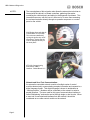
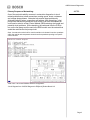
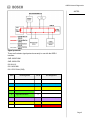
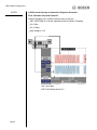
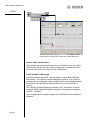
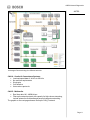
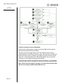
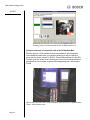
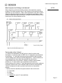
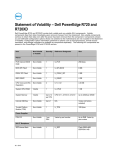
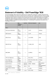
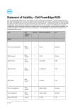
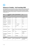
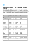
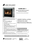
OBD II Network Diagnostics
Diagnostics Using OBD II
Data Bus Communication Networks
NOTES:
Overview:
Vehicle On-Board Control Modules are changing the automotive industry in
two related areas. The first area concerns the expansion and use of multiple
on-board control units. Today’s modern vehicle will have on-board control
modules controlling vehicle components such as the engine, antilock braking
system, transmission, instrument panel, chassis and body control functions,
to name just a few. An on-board control module does more than just make
sure its own input and output devices work correctly. The on-board controller
also participates and communicates in one or more communication networks
in the vehicle. These vehicle networks exist to allow the sharing of
information among components and to reduce the numbers of wires and
sensors required in the vehicle.
The second area in which
microcontrollers are changing the
automotive industry concerns the
way we interact with our vehicles.
Computers are now common in the
passenger area and consumers
can now interact with their vehicles
in a variety of ways. This allows
consumers to run already familiar
programs in the vehicle — email,
GPS navigation, calendar
management, etc.
Lexus Navigation Center
Page 1
OBD II Network Diagnostics
NOTES:
The second phase of this migration also allows the automotive technician to
interact with the vehicle’s on-board controllers, gathering information,
controlling the vehicle directly and aiding in the diagnosis of problems. This
interaction can occur with the use of a scan tool or in some case accessing
the on-board controller directly through an operation sequence or a control
panel on the vehicle.
2005 Dodge Neon with Idle Air
Control Motor DTC (P0508).
This code was obtained by
cycling the ignition key on/off
three times. Notice how the
code is displayed directly on
the dash panel.
KTS 200 Communicating
with Generic OBD II
interface. Robert Bosch LLC
Network and Scan Tool Communication:
An automotive controlled network consists of multiple series of control
modules electronically communicating complex information and requests in a
digital language format. This digital language is known to technicians as
“vehicle protocols”. Modules can be connected on the network in serial or
parallel interface. The term used for this type of communication interface is
called “Multiplexing” and can be carried through single or dual circuits. When
a scan tool is connected and interfaced into the network it should be
considered as one other control module on the network.
Page 2
OBD II Network Diagnostics
Primary Purposes of Networking:
NOTES:
One of the major driveability concerns in automotive diagnostics is circuit
related problems due to bad connections creating opens, shorts, resistance
and voltage drop problems. Networks help resolve these problems by
eliminating miles of wires, connections and splices. With networking, a fuel
pump circuit that would normally be wired to the PCM to be commanded on
could now be wired to a Rear Control Module (REM) reducing wire length and
potential circuit problems. With networking, the command from the PCM to
turn on the fuel pump could be sent to the REM module over the network that
would then activate the fuel pump circuit.
Note: As networks evolve look for control modules to be located in various quadrants
within the vehicle and components located near that quadrant reporting to a specific
control module.
2004 Volvo S 80 Control Module Network Configuration.
Circuit Diagram from CAS/SIS Diagnostics ESI[tronic] Robert Bosch LLC
Page 3
OBD II Network Diagnostics
NOTES:
Network Topology:
Linear: Interconnection of multiple ECU’s on
common linear bus. A multi-master principle is
generally used, allowing high stability with enhanced
fault localization. This system is used in drivetrain
and body network systems.
Ring: Short path interconnection of multiple ECU’s
in a fiber-optic series ring. The information passes
through each ECU. This system is used in
multimedia networks. Multimedia systems require
large volumes of data to be transferred in short
amounts of time. To transmit a digital TV signal with
stereo sound requires a data transfer rate of around
6 Mbit/s. MOST (Media Oriented Systems
Transport) can transfer data at a rate of 21.2 Mbit/s.
Star: Interconnection of multiple ECU’s in a star
structure network control by central master ECU.
This system uses a master-slave, time triggered
protocol. The network is designed as a low cost, local sub-system single wire
interconnect network for use in on-off devices such as car seats, door locks,
sunroofs, rain sensors and door mirrors.
Terminating Resistors:
Terminating resistors are used in CAN systems to create proper electrical
load between the CAN_H and CAN_L circuits. This load helps to reduce
electrical noise on the data circuits, which allows for a cleaner voltage signal
on the data bus.
Terminating resistors in the high speed CAN systems are required to be 120
ohms with a maximum range of 118-132 ohms. Lower speed CAN systems
may use different values. CAN systems can use split termination, which
means there may be more than two terminating resistors in the system.
Terminating resistors may be physically located inside any of the control
modules connected to the CAN harness, with a junction connector. The
resistors may also be part of the wiring harness. Terminating resistors may
or may not be identified in circuit wiring diagrams. Do not attempt to conduct
wiring diagnostic fault procedures such as voltage or resistance tests without
proper service information.
The figure on the next page shows an example of a CAN system with
terminating resistors.
Page 4
OBD II Network Diagnostics
NOTES:
Signal protocols:
There are five basic signal protocols currently in use with the OBD-II
interface.
SAE J1850 PWM
SAE J1850 VPM
ISO 9141-2
ISO 14230 KW
ISO 15765 CAN (C&B)
Pin #
Pin Assignment
1
Pin #
Pin Assignment
9
2
SAE J1850 (SCP Bus +)
10
SAE J1850 (SCP Bus -)
3
ISO 15765-4 CAN MS (Bus +)
11
ISO 15765-4 CAN MS (Bus -)
4
Chassis Ground
12
5
Signal Ground Return
13
6
ISO 15765-4 CAN Hi (Bus +)
14
ISO 15765-4 CAN Low (Bus -)
7
K Line of ISO 9141
15
L Line of ISO 9141
16
Fused Battery Power
8
Page 5
OBD II Network Diagnostics
NOTES:
J1850 from the Society of Automotive Engineers Protocols:
Ford “Standard Corporate Protocol”:
Protocol operates at 41.6 kB/sec with two wires on the bus.
_ SAE J1850 PWM (41.6 kbaud, standard of the Ford Motor Company)
_ Pin 2: Bus_ Pin 10: Bus+
_ High voltage is +5 V
SAE J1850 PWM
MTS 5100 Robert Bosch LLC
Page 6
OBD II Network Diagnostics
General Motors Class 2 Bus:
NOTES:
Protocol operates at 10.4 kB/sec with one communication wire. Chrysler also
has an adaptation of the GM Class 2 protocol.
_ Pin 2: Bus+
_ Bus idles low
_ High voltage is +7 V
_ Decision point is +3.5 V
_ Message length is restricted to 11 bytes, including CRC
SAE J1850 VPM
ISO 9141-2 from the European-influenced International Standards
Organization:
This is a single-wire where the ISO modules talk only when asked and only to
the scan tool, not to each other. This protocol is slower than GM and
Chrysler versions of SAE J1850. The ISO 9141-2 protocol has a long
wake-up call which allows for each control module to report PID data.
ISO 9141-2 protocol has a data rate of 10.4 kbaud and is primarily used in
Chrysler, European and Asian vehicles.
Page 7
OBD II Network Diagnostics
NOTES:
_ Pin 7: K-line
_ Pin 15: L-line (optional)
_ UART signaling (though not RS-232 voltage levels)
_ K-line idles high
_ High voltage is Vbatt
Just because a vehicle has an ISO protocol does not mean that the control
modules are unable to talk to each other. An example would be a 2001
Volkswagen Passat where the modules talk to each other on a CAN protocol
network. The CAN protocol is then transmitted to the IP instrument cluster
module where the signal protocol is converted to ISO format for
communication with the scan tool.
ISO 9141-2
ISO 14230:
In use by 1997, ISO 14230 was an upgrade to ISO 9141-2. One of the major
enhancements of ISO 14230 was a faster wake-up call.
_ ISO 14230 KWP2000 (Keyword Protocol 2000)
_ Pin 7: K-line
_ Pin 15: L-line (optional)
_ Physical layer identical to ISO 9141-2
_ Data rate 1.2 to 10.4 kbaud
Page 8
OBD II Network Diagnostics
CAN Systems:
NOTES:
Controller Area Network (or CAN) is the latest communication system within
the automotive world. CAN is a means of linking all of the electronic systems
within a car together to allow them to communicate with each other. As
on-board computers increase, so does the number of different electronic
systems. Today’s modern vehicles may have as many as 50 or more
on-board computer systems on them. The information recorded and
processed by each control module is often used by one or more control
modules on the system. A requirement for a standardized means of quickly
passing information between the control modules was needed leading to the
development of CAN.
CAN History:
CAN protocol was created in 1984 by Robert Bosch Corporation with
anticipation of future advances in on-board electronics. The first production
application was in 1992 on several Mercedes-Benz models. CAN is now
being used on more and more new vehicles. By 2008, all new vehicles sold
in the U.S. will be required to have a CAN-compliant diagnostic system.
CAN Protocols:
ISO 15765 (CAN-B&C)
CAN-B, the medium-speed network (nominally about 125 kB/sec), will be
used for body electrical systems and normally will operate at 83.3 kB/sec. On
some Mercedes cars, there may be as many as 30 modules on the CAN-B
bus.
_ Pin 3: CAN High
_ Pin 11: CAN Low
CAN-C is a 500 kbit/s high speed two-wire system for powertrain,
transmission and ABS modules. CAN-C is intended to operate at a
500 kB/sec baud rate, about 50 times faster than GM's Class 2 data bus
version of J1850 and over 60 times faster than ISO 9141-2.
_ Pin 6: CAN High
_ Pin 14: CAN Low
Note that Pins 4 (chassis ground), 5 (signal ground) and 16 (battery positive)
are present in all configurations.
The next page shows a CAN_High and CAN_Low waveform.
Page 9
OBD II Network Diagnostics
NOTES:
Screen Capture using KTS 570 lab scope Robert BoschLLC
Internal CAN Communication:
CAN networks can communicate internally, but not with the scan tool. Many
CAN modules will talk with each other and a gateway; or translator module,
will convert the protocol so a scan tool can understand it.
CAN Translators VW Example:
Instrument clusters from 08.99 > are integrated into the vehicle CAN Data
Bus network. The CAN-Bus on-board diagnostic Interface “J533” (which is
integrated into the instrument cluster) enables data to be exchanged between
the vehicles CAN Data-Bus network and the Data Link Connector (DLC)
“K-wire”.
The CAN-Bus On-Board Diagnostic Interface “J533” has specific on-board
diagnostic (OBD) capabilities that are accessed by using scan tool address
word 19 – “Gateway”.
The next page shows a network diagram of a VW Passat with three different
networks.
Page 10
OBD II Network Diagnostics
NOTES:
Volkswagen Passat showing four different networks
CAN A: Comfort & Convenience Systems:
• Low/med speed data of 1k bit/s to 20k bit/s
• No real-time requirements
• Single wire
• Cost effective
• Uses various protocols
CAN D: Multimedia:
•
•
Real time data 1M – 400M bit/sec
Fiber-optic network protocol with capacity for high-volume streaming,
include automotive multimedia and personal computer networking.
The graphic on the next page shows a fiber-optic CAN_D network.
Page 11
OBD II Network Diagnostics
NOTES:
CAN-B
Audio
Aux
MOST
Video line
Lin
CAN-D
A Growing List of CAN Applications:
Below is a list of some vehicles that are currently in CAN compliance. CAN
compliant means that the CAN network broadcasts diagnostic information to
the scan tool (Pins 6 & 14 or 3 & 11) in CAN protocol language. Many scan
tools have to be updated with CAN module adapters to communicate at the
higher baud rates that CAN systems produce.
2003 Ford Excursion
2003 Ford Focus and Thunderbird
2003 Lincoln LS
2003 Saab 9-3
2004 Cadillac CTS, XLR and SRX
2004 Ford Explorer
2004 Ford Taurus
2004 Mercury Mountaineer
2004 Mazda 3 and RX-8
2004 Volvo S40
2003 Ford F-250 and F-350
2003 General Motors Saturn ION
2003 Mazda 6
2004 Buick Rendezvous
2004 Dodge Durango
2004 Ford F-150, E-250 and E-350
2004 Lexus LS430
2004 Mercury Sable
2004 Toyota Prius
2005 Audi A4 and A6
2005 Chevrolet Equinox
2005 Chevrolet Trailblazer EXT
2005 Dodge Dakota and Magnum
2005 Ford Escape and Expedition
2005 GMC Envoy ESV and XL
2005 Jeep Grand Cherokee
2005 Lincoln Town Car
2005 Pontiac G6, Grand Prix and GTO
2005 Mazda MPV and Tribute
2005 Saab 9-7X
2005 Cadillac STS
2005 Chevrolet SSR
2005 Chrysler 300C
2005 Ford E-150
2005 Ford Freestyle
2005 Isuzu Ascender
2005 Lexus LS400 and GX470
2005 Mercury Mariner
2005 Land Rover LR3
2005 Mercedes-Benz SLK350
2005 Toyota Avalon
2005 Buick LaCrosse, Rendezvous and Rainier
2005 Chevrolet Cobalt, Corvette and Malibu
2005 Mercury Grand Marquis, Montigo and Sable
2005 Ford Crown Victoria, Five Hundred, Focus and Mustang
2005 Toyota 4Runner, Sequoia, Tacoma and Tundra
2005 Volvo S60, S80, V50, V70, XC90
Page 12
OBD II Network Diagnostics
Strategy Based Diagnostics
NOTES:
General Motors developed strategy-based diagnostics for their technicians
and the diagnostic procedure can be used on all vehicle applications.
• Verify the customer concern: A technician needs to know how the system
is supposed to function normally before deciding that the system is
malfunctioning. A thorough customer interview, or a diagnostic worksheet
filled out by the customer, is necessary before troubleshooting can begin.
• Preliminary checks: Operate the suspect system and evaluate its
performance. Perform a thorough visual inspection of all components,
including fuses, connectors, grounds and harness routing. This is also an
ideal time to pull up the service history on the vehicle.
• Perform published diagnostic system checks. If there is a published
diagnostic procedure that will help you narrow down the cause of the
problem, use it first.
Note: This is the time to connect the scan tool and request diagnostic
information from the control modules on the network.
• Check for bulletins: If you have access to published service bulletins for
the vehicle, search those for a possible fix. This can save time in the long
run. You can also print safety bulletins for your customers at this point, as an
added value.
• Stored diagnostic trouble codes (DTC’s) and symptoms with no
DTC's: If there is a hard trouble code, then follow the diagnostic procedure
for the particular DTC. If you have a repeatable symptom, then use the
Symptom Charts. Both these procedures will quickly help you narrow your
diagnostic focus.
• No published diagnostics: When there is no DTC stored and no
matching symptom for the condition in the service manual, you will have to
develop your own diagnostic process based on your understanding of how
the circuit operates. This is the time when there is no substitute for advanced
systems training.
The graphic on the next page shows the diagnostic flow chart for Strategy
Based Diagnostics.
Page 13
OBD II Network Diagnostics
NOTES:
Verify the Customer Concern Expanded:
Know how the vehicle systems operate, the driving habits of the customer
and the environmental driving conditions.
The figure on the next page shows a 2001 VW Passat Central Locking
Module located in a pan below the driver’s seat. Mud and snow can leak into
this box and short out the computer, thus killing the communication with the
Scan Tool. At this time there is no TSB on this problem, but you can find
information on the problem by browsing the Internet.
Even though the Internet is a great resource for information, you should take
the time to make sure the information is accurate by checking other websites.
Note: Bosch does not support, promote, or endorse any websites other
than its own company website (www.Bosch.com).
Page 14
OBD II Network Diagnostics
NOTES:
Graphic captured from the Internet
Perform published diagnostic system checks expanded:
Connecting the Scan Tool:
Is there power on Pin 16 to power-up the Scan Tool? Many OEM scan tools
may not have internal batteries and will require Pin 16 to have power in order
for the scan tool to communicate. Be aware that no power on Pin 16 may
affect some aftermarket scan tools (consult your operator’s guide). Many
times Pin 16 will not have power due to something as simple as a blown
cigarette lighter fuse. Remember Pin 16 is Battery Power Un-switched.
Many technicians panic when their scan tool doesn’t power up off the 16 Pin
connector. In some cases the technician will think the computer or
computer(s) are dead and not communicating with the scan tool. A quick
work around is to power up the scan tool through an alternate battery source
or AC power source. Remember Pin 16 has nothing to do with
communication, it is only there to power up your scan tool for diagnosis.
Pins 4&5 are also important as one of these grounds will be needed for your
Scan Tool to power up the OBD II link and establish a reference link for scan
tool communication. If you are having communication problems it is
imperative that you check the integrity of these grounds. In some instances
one of these grounds may be open or have high resistance. There is also a
possibility that the scan tool might complete a ground that is faulty when the
scan tool is not connected. If the OBD connector has power or ground
problems you should validate the connections when the scan tool is removed.
Page 15
OBD II Network Diagnostics
NOTES:
Checking Power to Chassis Ground (KTS 570) Robert Bosch LLC
Using the scan tool in conjunction with a 16 Pin Breakout Box:
Different types of 16 Pin breakout boxes are available in the aftermarket.
Some breakout boxes hook up in parallel, allowing you only the ability to
probe the circuit with a scope or DVOM. Other breakout boxes like the AES
LineSpi, hook in a series circuit, allowing the scan tool to command data bus
protocols from the on-board computer while diagnosing with a lab scope or
DVOM.
AES LineSpi, MTS 5200, MTS 3100 connected to Ford ISO 9141-2 in Module Status
Check. (www.aeswave.com)
Page 16
OBD II Network Diagnostics
What Computers Are Talking on the Network?
NOTES:
When diagnosing vehicle driveability problems with networked computer
modules, know what computers are on the network for the particular vehicle
application you are working on. Many vehicle applications may add or delete
computer modules based on the amount of accessories and options. Most
electronic information systems will have a computer network schematic at the
beginning of the wiring diagrams section.
Ford Motor Company Network Schematic (Ford Technical Publications)
http://www.fordinstallersupport.com/
The Invention of the “U Code”:
“U” codes were classified by the SAE as the 4th item for trouble code
descriptions. In the early years of OBD II the “U” designation was classified
as undefined. “U” codes are becoming more prevalent on today’s modern
vehicles adding more advanced on-board diagnostics. Control modules are
now programmed to know what other modules they should be in
communication with on the network. Based on network communication
problems, a “U” code could be set if a particular module was not
communicating on the network. Flash reprogramming new control modules is
necessary because new control modules need to know how that particular
vehicle is configured in order to perform their function on the network
properly.
• The first character identifies the system related to the trouble code.
−
−
−
−
P = Powertrain
B = Body
C = Chassis
U = Network (for years “U” was undefined)
Page 17
OBD II Network Diagnostics
NOTES:
Example of Generic U-Codes:
U0100 Lost Communication With ECM/PCM “A”
U0101 Lost Communication With TCM
U0102 Lost Communication With Transfer Case Control Module
U0103 Lost Communication With Gear Shift Module
U0104 Lost Communication With Cruise Control Module
U0105 Lost Communication With Fuel Injector Control Module
U0106 Lost Communication With Glow Plug Control Module
U0107 Lost Communication With Throttle Actuator Control Module
U0108 Lost Communication With Alternative Fuel Control Module
U0109 Lost Communication With Fuel Pump Control Module
U0110 Lost Communication With Drive Motor Control Module
U0111 Lost Communication With Battery Energy Control Module “A”
U0112 Lost Communication With Battery Energy Control Module “B”
U0113 Lost Communication With Emissions Critical Control Information
U0114 Lost Communication With Four-Wheel Drive Clutch Control Module
U0115 Lost Communication With ECM/PCM “B”
U0116 Reserved by Document
U0117 Reserved by Document
U0118 Reserved by Document
U0119 Reserved by Document
U0120 Reserved by Document
U0121 Lost Communication With Anti-Lock Brake System (ABS) Control
Module
Example of GM Manufactured Specific “U” Codes:
U1000
U1001
U1002
U1016
U1016
U1017
U1026
U1027
U1040
U1041
U1042
U1043
U1056
U1057
U1161
Class 2 Communication Malfunction
U1254 - Loss of XXX Communications
U1015 - Loss of serial communications for Class 2 devices
Loss of Class 2 Communication with VCM
Loss of Communications with PCM
U1025 - Loss of serial communications for Class 2 devices
Loss of ATC Class 2 Communication
U1039 - Loss of Serial Communications for Class 2 Devices
Loss of Class 2 Communications with ABS
Loss of EBCM Communication
Lost Communications with Brake/Traction Control System
U1055 - Loss of Serial Communications for Class 2 Devices
Loss of Communications with RSS\
U1060 - Loss of Serial Communications for Class 2 Devices
Loss of PDM Serial Data
Bosch Diagnostics conducts courses on this subject as well as many
other topics in the field of automotive and diesel technology. For more
information on courses in your area, go to www.boschtechinfo.com or
call (800) 321-4889.
Page 18