1
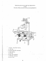
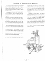
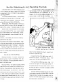
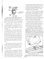
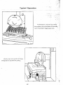
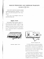
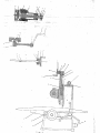
MACHINEW DIVISION
6465 18 MILE ROAD
STERtiNG HEIGHTS, MI 4831 4
PHONE:
(586) 751 -3500* 1-000-860-1740
9 , 'T:mjp"a
(97J&acLJfl
j~@;fii]
- ~ . . ~ - c ! J
FAX:
(556) 731 -7464 * 1 -800-862-1740
MODEL SG-612
SURFACE GRINDER
THANK YOU FOR PURCHASING WlTH KBC MACHINERY. ALL KBC
MACHINES ARE BACKED BY OUR 1 YEAR PARTS REPLACEMENT
WARRANTY. WHEN USED AS INTENDED, AND WlTH PROPER
MAINTENANCE THIS MACHINE WILL PROVIDE YOU WlTH YEARS OF
TROUBLE-FREE SERVICE. I F YOU NEED PARTS SIMPLY FILL OUT
THE PARTS REQUEST FORM, AND FAX OR E-MAIL YOUR REQUEST.
ALL OTHER QUESTIONS PLEASE CONTACT US @ :
KBC MACHINERY
6465 18 MILE ROAD
STERLING HEIGHTS,MI 48314
PH (800) 860-1740
FAX (800) 862-1740
[email protected]
WWW.KBCTOOLSANDMACHlNERY.COM
w w w . K B C T O O L S .C O M
PARTS REQUEST FORM
YOUR COMPANY NAME::
STATE/PROVINCE
YOUR NAME
PHONE
FAX
#
+ EXT
#
MACHINE INFO:
MAKE~MANFACTURER
MODEL NUMBER
YEAR MADE
PARTS REQUESTED:
PART#
DESCRIPTION
PLEASE INCLUDE C O P Y ( S ) OF THE PARTS DRAWING FROM THE
MANUAL AND CIRCLE THE PARTS NEEDED
FAX PARTS REQUEST TO ( 8 0 0 ) 862-1 7 4 0
E-MAIL PARTS REQUEST TO: machinery@kbctools corn
.
THANKS; KBC MACHINERY
-
MICHIGAN
,..
c..
.,,..
- .. .
,
.
:
,
.
., .
'
.
,
...
HAND OPERATED
SURFACE GRINDING: MACHINE
SERVICE MANUAL
IACCURACY
IFAST PRODUCTION
ILOW MAINTENANCE
Operating Controls and Set-Up Adjustments
of the
Precision Micromaster Surface Grinding Machine
,-
.-
-
1. Spindle
. .
..
.
start-stopv Buttons.
..
2. Sable Dog.
,
-
"
..
, .
~ '.Z ~ , . . .
3 . ..Vertical Adjustment Handwheel.
>.
,,
~
4. Table ~ o ~ s t o ~ .
.
5. ~ a b l e - ~ o ~ .
6.--Table T r a v e l Handwheel.
7. Cross Feed ,Handwheel
8. Shield Plate.
Installing or Relocating the Machine
I n l i f t i n g or moving the machine i t i s rexomended
that the rope be rigged as shown in Fig 1. Place -~~
---~.
wooden blocks or protective material be ween the
~
~
~
~
~
rape and the machine wherever the rope i s 1 iable to
.
damage any part.
If available, a '!tork-)ar~ truck" can be used to
m o r e t,e
machine.
~
.
under any corngrpr corners that m a y be-low.Mak
~
~~
,
Precision spirit level m d drive a woodcn ehingla
The I i f t I S located under s!eel
bars positioned in the holes : i n the base of
the
sure that a l l four corners arr supported; then t i g t
ten the l a g screws,
test
surface again i n both
the level of
directions
tab1
and readjust i
necessary.
Connecting
to
Power Supply.
The machine
should be connected to the power I ine and proper.
macnine
l y grounded.
CAUTION: DO not push on the uprignt when m o r -
should
ing the machine unless the rods and strap used i n
mounted on the right side of the machine.
shipping are i n pl8ce.The uprighl i s a s l i d i n g m e m -
the
The l i n e s f r o m the power
be connected to
the magnetic
Checking Motor Rotation.
source
starter,
..
Press the magnetic
her h e l d on by i t s own ~ e ~ g and
h t the cross feed
starter "start" and observe the direction o f Spindlr
screw. Considerable dclmaqe can be caused
rotation.
C ~ O S S: e n 3
screw I I
to the
uprrght i s t i l t e d on i t s w3ys.
r h C mD:hln~ should be located on a level foundat i o n or !loor, a s o l i d vibrationies;
foundation being
it
3vft
i s frgn
3
i e l o l a wooden floor,locate
heam and on a p o r t ~ o n01 rhe lloor
3: \rlSrat$on.
ura,oicably
which
In case the foundation or floor
transmits vib:ation to the machir#e,set
the mac'71ne on a s";ock-aSsorbing
pad.
'ii"8mc tile rnachlne i n position, test the surface
o f !he tnslc
both long~tudinal any cross w i t h a
:lockwis~ as
seen from the front o f the r n n c h ~ n e . I f the
direc-
tion o f rotation i s countercIockwlse, Change two
wires at the starter.
essential where the finest finish must be produced.
I f the machine m u s t .
The s ~ i n d l eshould rota:+
,
Set-Up ~ d j u s t m e n t s
.
,
Since the clamp
. screw
. . - merely holds the thrust
~
collar i n position and &es not govern the closeness
. ~. .
.
.
.~
. .
p
~
-
~.
.~.
of adjustment, there i s no reason to use excessive
. .
clamping pressure.
The wheel should f l t easlly on tM *meel s l i e v
.
~
~~
~
~
yet not l&sely,
~
.
..
.
when grinding
shoulders with the outer face Of the wheel,
clamp screw can be released,
leaving the
.
,,
. .
be c
tered accurately and w i l l consequently be Out 0
. ,
..
.* ..
balance. Do not wrapthe sleeve with psper etc. to
., ,
For normal surface grinding or
-
for If i t Is l w s e lt.cennot
,
r:;
.. .
-49
.
. . .:.
. ,.
.
~
;:.$
., ,
,,,,
~ '.:>,-~.
.- .
.
make a wheel f i t when the hole i s too large. i t is
.
.:.
,
',
;
the
thrust
springs to take up end play automatically.
Wheel Speed. when the Spindle i s driven by a
60 cycle direct drive motor, the full load speed i s
3450 R.P.M.
Wheel
using a 7" diameter wheel,
Y2"
tnick.
Guard. The wheel guard is a one-pi+
j n i t cover on the front. The
cover opens upward
and i s held closed by four knurled-head
screws.
All that i s required to remove the wheel i s to l i f t
the cover.
However, i t i s necessary to remove the wheel by
guard-remove the wheel.
Two clamp screws located on the clamping
edge
af the whee! guard support can be loosened and the
guard tipped either side of horizontal if necessary
Warning: Always make sure that the
guard i s
securely clamped before starting the machine; and
The vertical adjustment hand wheel
i s shown near the top of the uprtght
never run a wheel without having the guard and i t s
better from all standpoints either to discard such
cover i n place.
a wheel or recase the core.
Care and Use of Grinding Wheels
A wheel that f i t s a trifle tightly may crack
Selecting the Wheel.
In order tc
produce the
desired quality of work i n the shortest time
real
care i s necessary i n choosing the wheel which
forced on the sleeve.
if
If the hole is only a l i t t l e
under size i t car easily be scraped out to f i t .
is
i
Warning: Before mounting a wheel,
best for the job at hand.
hang i t in
the air on one finger; then lightly tap the edge of
Mounting Wheels. One general-purpose grinding
the wheel and see if i t gives a clear ringing sound.
wheel and one wheel sleeve are furnished with the
A wheel that does not ring clear i s probably cracked
rnachine. When additional wheels are used, extra
and should not be used.
wheel sleeves should
be procured so that
each
wheel can be kept on i t s own sleeve.Thus, in -1 3cg
i,,g
from one type of wheel to another, the wheel
The inner of the two flanges between the wheel
i s mounted is a part of the wheel sleeve. The outer
,
re-
flange consists of a s t e e l disk or washer,which i s
,
;ain concentric,requiring only a minimum a mount
keyed to the wheel'sleeve to keep i t from turning
.
3f truing.
and loosening the clamping nut.
and sleeve can be changed as a unit and w i l l
:
:.
~,;ij3
.....
-. ,.j$$
.
~
,.?.,. ,I
a.
.~
-
..-
truing should be discarded or returned to the wheel
mmufacturer-though i n cases of necessity the con-
STEEL
~
~
~
~
~
-~~~~
- dition
--
may be corrected by digging outpart of
the^^^-
wheel beneath the flange and f i l l i n g with leadas
indicated by a test for static balance.
Wheel Truing. A wheel truing fixture i s furnished
Proper mounting
of grinding wheel.
w i t h the machine.
The truing diamond ( furnished )
may be applied to the wheel along any 1 ine on the
lower half of the wheel circumference, though preferably at the bottom of the wheel as show.
To equalize the clamping pressure, washers of
cardboard or rubber should be placed between
wheel
and the two flanges,
Most wheels of the s i r e
used on this machine have a ring of
paper
on eacn sloe,
heavy blotting
which serves the Purpose.
Using the pin wrench
furnished,
tighten the
Clamping nut enough to hold the wheel
place On the sleeve.
the
firmly
in
Do not tighten too much,how-
ever, as excessive clamping pressure w i l l
crack
prevent gouglng, the center line of the diamond tool
should point slightly the center of the wheel
i n the
direction of movement of the wheel surface.
The wheel should be trued each t i m e i t i s put on
i n e spindie and wnenever i t becomes loaoed,
or glazed.
duli
Pass the diamond across the wheel with
a slow, steady manual cross feed, taking care to
avoid any longitudinal movement of the table.
In truing a wheel for for rough grinding, take a
cut aWut O.Olm/m deep i n one pass of the diamond
the wheel.
Changing Wheels.
To
In removing a wheel sleeve
from the spindle, always
use the wheel
puller (furnished with the machine)
chance of cracking ithe wheel or
sleeve
to avoid any
damaging the
spindle bearings by pounding. Remove the spindle
across the wheel
and finish with a similar cut
0.000,25" deep. I f the wheel is to be used for finishing grinding,take two O.Olm/m cuts; then take twc
or three additional cuts removing about 0.000,25"
eact
time, and f i n a l l y pass the diamond across the wheel
once or twice without further advance of the wheel.
nut ( this nut has a left-hand thread the outer member of the wheel sleeve puller into the wheel sleeve
and tighten the inner screw against
the spin-die,
thus, loosening the wheel sleeve without harmful
jarring.
I n putting a wheel o n t h e spindle, examine both
the wheel sleeve hole and the spindle.end are perfectly clean. Then s l i p the sleeve onto the spindle,
seat i t by hand and tighten by means of the clamping nut and wrench.
Balance of Wheel.
It i s essential that the wheel
run perfectly true and without vibration.
Grinding
wheels are balanced by the manufacturer and, in the
I.
. .
..
rr
.
.
.
case of wheels of the size used on. this machine,
should not require attention i n this respect other than
truing. A whbel that runs badly out of balance after
Wheel
truing fixture
i n use.
The figures stated are a o ~ r o x i m a t eand under some
conditions should be varied somewhat to give desired
results.
Movable wheel slide upright contributes
immeasurably to accurate slot grinding.
optional M e c h e n i s m ' a n d Additional Equipment
p~
,
~~
~~
~
~
~
(Furnished a t ~ i t r a c o s t )
" . ...~.-.
.
-
-
~
~~
~-~~
-
~.
Various items of add~tionalequipment avatlable
as extras are described and illustrated i n this chapter.
Instructions are also given on their
set-up
and use.
These
extras include Magnetic Chucks and
Precision Grinding Vlse.
Magnetic Chucks
I:
;,I
I;,,
I! ;
1
!j
-
.
The Rectangular Model Permanen: Magnet Cnucks provide a quick, easy means of holding a vaiiety of ferrous work for surface
grinding.
A 1800
movement of the control lever turns the chuck on
8
or o f f ; and since the chuck does not use electric
I!
i:
current, i t can be left turned on for long as desired
8
,$
without heating.
Precision Grinding Vise
Permanent Magnet
Chuck.
For highest accuracy in grinding work parallel,
the top surface of the chuck should be ground each
t i m e the chuck is
mounted on the machine.
Be
sure that the chuck i s turned on before doing this,
and remove only the minimum amount of metal
required to grind the entlre top surface.
The chuck shouldnot be subjected to excessive
heat, shocks or blows, and the top sho!
' be kept
free from pits and scratches. Regrind the top sur,face occasional 1 y i f necessary ,as a smooth surface
i s essential for grinding work parallel.
...
1 GRINDING
-
~
~
~
~~~
~
SPINDLE
.
~
2
~
'
~-~~
~
- 30 B E A R I N G
-
~-
~
~
FRONT~NUT
. .
.... 3 1 ELEVATING S E A T
.
. .
~
3
GRINDWHEEL LOCKING NUT
32 ELEVATING B A S E
4
GRINDWHEEL LOCKING B A S E
21 L " C K - W € €
5
FRONT LOCKING NUT
p
6
BEARING
35 SADDLE MOUNT
7
GRINDWHEEL BLOCK
36 P R E S S B A R
8
BEARING
37 B A S E
9
CONNECTION B O X
38 POWER
10
MOTOR C A S E
1'1
HANDLE
12
HANDLE B A R
SWITCH
(PLASTIC)
13 GUIDE ROD
14
WORKING TABLE
43 LIFTING RING
HEXAGON SCREW
44 LOCKING SCREW
1
!
RACK
GEAR
46 PULLEY
KEY
47 ELEVATING W a R M
HANDLE
48 GUIDE PLATE
HANDWHEEL
49 B E A R I N G BLOCK
DIAL
50 GEAR
B E A R I N G BLOCK
BEARING
LONGITUDINAL NUT
LONGITUDINAL W O R M
HANDLE
HANDWHEEL
KEY
DIAL
BOX
!
!