1
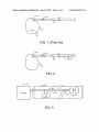
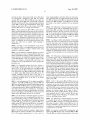
US 20070203547Al
(19) United States
(12) Patent Application Publication (10) Pub. No.: US 2007/0203547 A1
(43) Pub. Date:
Costello et al.
(54)
MEDICAL DEVICE IDENTIFICATION
(76) Inventors: Benedict James Costello, Berkeley, CA
(US); Lawrence Arne, Redwood City,
CA (U S)
Correspondence Address:
BOZICEVIC, FIELD & FRANCIS LLP (PRTS)
(PROTEUS BIOMEDICAL,INC)
1900 UNIVERSITY AVENUE, SUITE 200
EAST PALO ALTO, CA 94303 (US)
(21) Appl. No.:
(22)
Filed:
Publication Classi?cation
(51)
Int. Cl.
A61N 1/00
(52)
us. c1.
(2006.01)
.............................................................. .. 607/59
(57)
ABSTRACT
Techniques are provided for accessing information about a
medical device or a related component. One or more inter
11/611,685
rogatable identi?cation elements are located in a medical
device. An interrogation device can communicate With the
Dec. 15, 2006
mation about the medical device, such as a manufacturer
identi?cation element(s), Which element(s) can store infor
Related US. Application Data
(60)
Aug. 30, 2007
Provisional application No. 60/ 750,983, ?led on Dec.
15, 2005.
205
|
name, a date of manufacture, an expiration date, con?gura
tion data, calibration data, and a list of enabled functions. In
certain embodiments, the interrogation device can also store
information in the identi?cation element at any time, such as
usage time or usage frequency.
[204
L/i/l
I
—-\\
202
201
[.I
Ll IIIJ
\QAS'J
Patent Application Publication Aug. 30, 2007 Sheet 1 0f 3
105
|
US 2007/0203547 A1
Q04
123g
-\
I
\
//
102
12345
101
10s
F|G.1 (PriorArt)
205
|
204
l/l/l
H
—-\\
l |
202
ET! WI 1
ZEQ'J
201
FiG. 2
K301
K302
//
'a
Controller
\IIE
\
I
L 306
304
FIG. 3
)
307 kaoaj
Patent Application Publication Aug. 30, 2007 Sheet 2 0f 3
US 2007/0203547 A1
K 401
I
t
Controller
r 405
#1- _J_
K406
\W
//
403)]- 1404
402
FIG. 4
K 501
r503
Controlier
//
_\ 504
502
FIG. 5
f 601
r 603
Controiler
l|IIi
604
602
FIG. 6
//
l
Patent Application Publication Aug. 30, 2007 Sheet 3 0f 3
US 2007/0203547 A1
(- 702
_! [.
r 703
Controller
//
"1 F "\
f
705
704
f
701
FIG. 7
f 802
r 803
Controller
//
‘\aos
I
f
801
f 961
f 902
f 903
f 904
a
I
|
I
f 905
Physical
Encoding!
contro?er
Memory
ink-‘3252a
Dgiodlng
00
B'Ock
BIDCK
FIG. 9
Aug. 30, 2007
US 2007/0203547 A1
MEDICAL DEVICE IDENTIFICATION
have a unique identi?er are located in a medical device. An
CROSS-REFERENCE TO RELATED
APPLICATIONS
interrogation device can communicate With the identi?ca
tion element in a number of Ways, e.g., Wirelessly, using one
or more existing pin connections, etc. The chip can store
[0001] This application claims priority to: US. Provi
unique identifying information about the medical device,
sional Application Ser. No. 60/750,983 ?led on Dec. 15,
2005; the disclosure of Which priority application is herein
INTRODUCTION
list of enabled functions. The interrogation device can also
store information in the chip at any time, such as usage time
or usage frequency.
Background
present invention Will become apparent upon consideration
incorporated by reference.
[0002]
Existing medical devices or components of medi
cal devices typically have serial numbers or bar codes on
them. For example, pacemaker can 101 shoWn in FIG. 1 is
an implantable medical device that is connected to a pacing
lead 102. Pacemaker can 101 has a serial number 103 etched
into its surface. Lead 102 also has a serial number 104
printed on a portion of the lead, typically next to a connector
105 that connects lead 102 to can 101.
[0003]
such as a manufacturer name, a date of manufacture, an
expiration date, con?guration data, calibration data, and a
A physician may Want to knoW the manufacturer
name, the lot number, or the date of manufacture of pace
maker can 101 or lead 102. HoWever, physicians often do
[0009] Other objects, features, and advantages of the
of the folloWing detailed description and the accompanying
draWings, in Which like reference designations represent like
features throughout the ?gures.
BRIEF DESCRIPTION OF THE FIGURES
[0010] FIG. 1 illustrates a pacemaker can and an implant
able lead that have serial numbers printed or etched onto
their surfaces, according to a prior art technique.
[0011] FIG. 2 illustrates a pacemaker can and an implant
able lead that has a chip embedded in the lead body,
according to an embodiment of the present invention.
not have easy access to a service manual that describes the
particular functionality of pacemaker can 101 and lead 102.
[0012]
Information about a pacemaker can be accessed online from
troller and an implantable lead that has a digital system,
according to an embodiment of the present invention.
a database by entering serial numbers 103 and 104 located
on the pacemaker can and lead.
[0004] A user may have to manually locate the serial
numbers, read the serial numbers, and then enter the serial
numbers into a database (e.g., using a keyboard). Because
FIG. 3 illustrates a schematic diagram of a con
[0013] FIG. 4 illustrates a schematic diagram of a con
troller and an implantable lead that has a digital system
connected to Wires in the lead through capacitors, according
to another embodiment of the present invention.
these steps are performed manually, they require time and
[0014]
are prone to error.
troller and an implantable lead having a digital system that
[0005] Some catheter devices have a small memory device
that is used to store con?guration or calibration data. The
catheter’s electrical controller reads the data in the memory
device and con?gures itself so that it can use the catheter
device correctly. HoWever, these catheters have one or more
extra pins that alloW the memory device to communicate
With the catheter’s electrical controller. This solution is not
ideal for implantable pacemaker leads, because these leads
FIG. 5 illustrates a schematic diagram of a con
is inductively coupled to Wires in the lead, according to yet
another embodiment of the present invention.
[0015]
FIG. 6 illustrates a schematic diagram of a con
troller and an implantable lead having a digital system that
is coupled to Wires in the lead through a transformer,
according to yet another embodiment of the present inven
tion.
use standardized connectors, such as IS-l or IS-4. Therefore,
[0016]
adding one or more pins is not possible. All of the available
pins have dedicated functions. Space is also at an extreme
troller and an implantable lead having a digital system that
premium, strongly discouraging the addition of pins.
[0006]
FIG. 7 illustrates a schematic diagram of a con
communicates With the controller Wirelessly using antennas,
according to yet another embodiment of the present inven
tion.
Therefore, it Would be desirable to provide a sys
tem that alloWs a physician to access information about a
[0017]
medical device, such as a pacemaker, Without having to
troller and an implantable lead having a digital system that
communicates With the controller Wirelessly using oscillat
perform manual steps and Without requiring an extra pin.
FIG. 8 illustrates a schematic diagram of a con
ing magnetic ?elds generated by coil antennas, according to
Relevant Literature
[0007] US. Pat. Nos. 5,058,588; 5,300,120; 5,425,375;
5,674,288; 5,855,609; 5,987,343; 6,044,283; 6,377,829;
6,405,087; 6,463,310; 6,466,808; 6,600,940; and Intema
tional application publication number WO06035351.
yet another embodiment of the present invention.
[0018] FIG. 9 illustrates a block diagram of a digital
system that can be used With a medical device, according to
another embodiment of the present invention.
DETAILED DESCRIPTION
SUMMARY
[0019]
According to the present invention, at least one
[0008] The present invention provides devices and meth
interrogatable identi?cation element (e.g., chip comprising
ods for automatically accessing information about a medical
an integrated circuit) is provided in a medical device. An
interrogation device (e.g., a controller) can extract informa
tion about the medical device from the identi?cation ele
device or a related component. One or more interrogatable
identi?cation elements, e. g., in the form of digital chips, that
Aug. 30, 2007
US 2007/0203547 A1
ment, e.g., Wirelessly, via an existing pin connection, etc. In
further describing various embodiments of the invention,
embodiments of the identi?cation element of the devices
Will be revieWed ?rst in greater detail, followed by a revieW
of other aspects of the invention, including devices and kits.
mission. Block 903 can also encrypt and decrypt the trans
mitted data to provide data security. Block 903 can also
perform data integrity encryption to control Who can Write
and re-Write data into memory 905. Block 903 can use a
variety of encoding/decoding schemes, such as fsk, ask, psk,
nZe, Manchester, etc.
Interrogatable Identi?cation Element
[0020] An aspect of the invention is an interrogatable
identi?cation element. As the identi?cation element is inter
rogatable, it can be interrogated or queried by an interroga
tion device, e. g., Which interrogation device may be in vivo
[0026] Controller block 904 extracts commands and data
from a bit stream received from the external interrogation
device (e.g., controllers 301, 401, 501, 601, 701, or 801).
Controller 904 can act upon the received commands to
perform a variety of functions. For example, controller block
or ex vivo and may communicate With the element Wire
lessly or via one or more Wires. As such, the interrogation
device can communicate With the identi?cation element to
904 can read data from and Write data to non-volatile and
volatile memory in block 905. Memory block 905 can be
obtain information from the element, Which information
may include unique identi?er information.
particular application. For example, memory block 905 can
[0021] The identi?cation element can store a variety of
machine-readable information about the medical device
With Which it is associated. For example, a manufacturer
name, a date of manufacture, a lot number, a serial number,
an expiration date, and a list of enabled functions can be
stored in memory on an identi?cation element associated
With a medical device. The interrogation device can read the
data from the memory and display the data to a user, e.g.,
physician or other health care professional, upon request.
This technique eliminates the chances of human error inter
fering With a proper identi?cation of the medical device and
saves time.
include any one or more of the folloWing technologies,
ROM, PROM, EPROM, EEPROM, FLASH, FEPROM,
DRAM, and SRAM. Data stored in memory 905 can be
secured through encryption or passWord protection.
[0027] An identi?cation element chip that is part of an
implantable medical device may be protected from the
environment inside a patient to prevent damage to the chip.
For example, the chip or the body of the implantable medical
device can be encased in a material that provides an effective
barrier to moisture and saline. In certain embodiments, the
chip may be “hermetically sealed,” e.g., as described in PCT
application serial PCT/US2005/0468l5 titled “Implantable
Hermetically Sealed Structures” and ?led on Dec. 22, 2005;
[0022] According to some embodiments of the present
invention, data can be stored in memory in a chip that is part
of a medical device at any time. For example, a controller in
an external device can keep track of the number of times that
the medical device has been used. The controller can also
keep track of the amount of time that the medical device has
been used. The controller can store this information in the
chip from time-to-time, and can use the stored information
to determine When the medical device has exceeded its
useful lifespan. After a maximum usage frequency or usage
time has been exceeded, the controller or other device can
disable the medical device or Warn a user against using it.
[0023] FIG. 9 illustrates a simpli?ed block diagram of a
digital system 901 in a medical device, according to an
embodiment of the present invention. Digital system 901 is
an example of digital systems 304, 402, 502, 602, 704, and
804, Where these elements are revieWed in greater detail
beloW. Digital system 901 is merely one example of a digital
system that can be used in a medical device and is not
intended to limit the scope of the present invention.
[0024] Digital system 901 includes a physical layer inter
face 902, an encoding/decoding block 903, a controller
block 904, and a memory block 905. Physical layer interface
902 contains the circuitry necessary to drive the signaling
onto a transport mechanism used in a particular implemen
tation, such as the Wired, Wireless, direct, inductive, and
capacitive coupling embodiments described above.
[0025] Encoding/decoding block 903
built around one or more memory technologies to suit the
encodes
and
decodes data for transmission to and from an external
interrogation device. Block 903 can implement error detec
tion and correction algorithms on data transmitted to and
from system 901 using Well-knoWn error correction tech
niques. Block 903 can also implement data compression and
decompression on the data to reduce its siZe during trans
and provisional application Ser. No. 60/79l,244 ?led Apr.
12, 2006; the description of hermetically sealed structures
provided in these applications being speci?cally incorpo
rated herein by reference.
[0028]
The identi?cation elements of the present invention
may be used With any of a variety of different types of
medical devices, Where the medical devices are, in certain
embodiments, implantable medical devices. By implantable
medical device is meant a device that is con?gured to be
positioned on or in a living body, Where in certain embodi
ments the implantable medical device is con?gured to be
implanted in a living body. Embodiments of the implantable
devices are con?gured to maintain functionality When
present in a physiological environment, including a high
salt, high humidity environment found inside of a body, for
2 or more days, such as about 1 Week or longer, about 4
Weeks or longer, about 6 months or longer, about 1 year or
longer, e.g., about 5 years or longer. In certain embodiments,
the implantable devices are con?gured to maintain function
ality When implanted at a physiological site for a period
ranging from about 1 to about 80 years or longer, such as
from about 5 to about 70 years or longer, and including for
a period ranging from about 10 to about 50 years or longer.
The dimensions of the implantable medical devices of the
invention may vary. HoWever, because the implantable
medical devices are implantable, the dimensions of certain
embodiments of the devices are not so big such that the
device cannot be positioned in an adult human. The function
of the implantable medical devices of the invention may
vary Widely, including but not limited to: cardiac devices,
drug delivery devices, analyte detection devices, nerve
stimulation devices, etc. Illustrative embodiments of various
types of implantable medical devices of the invention are
revieWed in greater detail beloW. According to certain
embodiments of the present invention, a chip or a digital
Aug. 30, 2007
US 2007/0203547 A1
system including a chip can be used With other types of
medical devices. Examples of medical devices that can
national Application No. PCT/US2005/046815 titled;
employ techniques of the present invention include cochlear
cation Ser. No. 11/368,259 titled: “Fiberoptic Tissue Motion
Sensor”; International Application No. PCT/US2004/
041430 titled: “Implantable Pressure Sensors”; US. patent
implant devices, retinal implant devices, diaphragm pace
makers, implantable EKG devices, implantable glucose sen
sors, physiological sensors, e.g., physiological pressure sen
sors, any type of medical device having a can and
implantable leads, and other types of medical sensors or
regulating devices. As another example, the techniques of
the present invention can be applied to implantable stimu
lation devices, e.g., gastro-stimulation devices and neuro
stimulation devices.
“Implantable Hermetically Sealed Structures”; U.S. appli
application Ser. No. 11/249,152 entitled “Implantable Dop
pler Tomography System,” and claiming priority to: US.
Provisional Patent Application No. 60/617,618; Intema
tional Application Serial No. PCT/USUS05/39535 titled
“Cardiac Motion Characterization by Strain Gauge”. These
applications are incorporated in their entirety by reference
herein.
[0029] In certain embodiments, the implantable medical
Vascular Leads
device is a cardiovascular device. By cardiovascular device
is meant a device that is employed in the treatment of, e.g.,
[0033]
in the delivery of therapeutic stimulation, in the sensing of
carriers that include one or more electrode satellite struc
Embodiments of the invention also include medical
be positioned in a cardiovascular structure, e.g., in or on the
heart, in a vessel, such as an artery or vein, etc.
tures, e.g., as described above. Carriers of interest include,
but are not limited to, vascular lead structures, Where such
structures are generally dimensioned to be implantable and
are fabricated from a physiologically compatible material.
With respect to vascular leads, a variety of different vascular
[0030] In certain embodiments as developed more fully
beloW in connection With the revieW of the ?gures, the
lead in certain embodiments is an elongated tubular, e.g.,
cylindrical, structure having a proximal and distal end. The
cardiovascular device is a lead, e.g., a cardiovascular lead,
Which lead includes at least one of the identi?cation ele
ments of the invention and at least one e?fector.
proximal end may include a connector element, e.g., a
hemodynamic parameters, etc., some aspect of a cardiovas
cular disease. In cardiovascular device embodiments, the
device or at least some portion thereof may be con?gured to
[0031] The medical devices may include a variety of
different e?fector elements. The e?fectors may be intended
for collecting data, such as but not limited to pressure data,
volume data, dimension data, temperature data, oxygen or
carbon dioxide concentration data, hematocrit data, electri
lead con?gurations may be employed, Where the vascular
standardiZed connector, such as an IS-1 or IS-4 connector,
for connecting to a control unit, e.g., present in a “can” or
analogous device. The lead may include one or more
lumens, e.g., for use With a guideWire, for housing one or
more conductive elements, e.g., Wires, etc. The distal end
may include a variety of different features as desired, e.g., a
securing means, etc.
cal conductivity data, electrical potential data, pH data,
[0034]
chemical data, blood ?oW rate data, thermal conductivity
data, optical property data, cross-sectional area data, viscos
ity data, radiation data and the like. As such, the e?fectors
or more sets of effectors, e.g., electrodes, satellites are
may be sensors, e.g., temperature sensors, accelerometers,
ultrasound transmitters or receivers, voltage sensors, poten
tial sensors, current sensors, etc. Alternatively, the e?fectors
may be intended for actuation or intervention, such as
providing an electrical current or voltage, setting an elec
trical potential, heating a substance or area, inducing a
pressure change, releasing or capturing a material or sub
stance, emitting light, emitting sonic or ultrasound energy,
emitting radiation and the like.
[0032]
E?fectors of interest include, but are not limited to,
those e?fectors described in the folloWing applications by at
least some of the inventors of the present application: US.
patent application Ser. No. 10/734,490 published as
20040193021 titled: “Method And System For Monitoring
And Treating Hemodynamic Parameters”; US. patent appli
cation Ser. No. 11/219,305 published as 20060058588 titled:
“Methods And Apparatus For Tissue Activation And Moni
toring”; International Application No. PCT/US2005/046815
titled; “Implantable Addressable Segmented Electrodes”;
US. patent application Ser. No. 11/324,196 titled “Implant
able Accelerometer-Based Cardiac Wall Position Detector”;
US. patent application Ser. No. 10/764,429, entitled
“Method and Apparatus for Enhancing Cardiac Pacing,”
US. patent application Ser. No. 10/764, 127, entitled “Meth
ods and Systems for Measuring Cardiac Parameters,” US.
patent application Ser. No. 10/764,125, entitled “Method
and System for Remote Hemodynamic Monitoring”; Inter
In certain embodiments of the subject systems, one
coupled, e.g., electrically coupled, to at least one elongated
conductive member, e.g., an elongated conductive member
present in a lead, such as a cardiovascular lead. In certain
embodiments, the elongated conductive member is part of a
multiplex lead. Multiplex lead structures may include 2 or
more satellites, such as 3 or more, 4 or more, 5 or more, 10
or more, 15 or more, 20 or more, etc. as desired, Where in
certain embodiments multiplex leads have a feWer number
of conductive members than satellites. In certain embodi
ments, the multiplex leads include 3 or feWer Wires, such as
only 2 Wires or only 1 Wire. Multiplex lead structures of
interest include those described in application Ser. No.
10/734,490 titled “Method and System for Monitoring and
Treating Hemodynamic Parameters” ?led on Dec. 11, 2003;
PCT/US2005/031559 titled “Methods and Apparatus for
Tissue Activation and Monitoring,” ?led on Sep. 1, 2006;
PCT/US2005/46811 titled “Implantable Addressable Seg
mented Electrodes” ?led on Dec. 22, 2005; PCT/US2005/
46815 titled “Implantable Hermetically Sealed Structures”
?led on Dec. 22, 2005; 60/793,295 titled “High Phrenic,
LoW Pacing Capture Threshold Implantable Addressable
Segmented Electrodes” ?led on Apr. 18, 2006 and 60/ 807,
289 titled “High Phrenic, LoW Capture Threshold Pacing
Devices and Methods,” ?led Jul. 13, 2006; the disclosures of
the various multiplex lead structures of these applications
being herein incorporated by reference.
[0035] In some embodiments of the invention, the devices
and systems may include onboard logic circuitry or a
processor, e.g., present in a central control unit, such as a
Aug. 30, 2007
US 2007/0203547 A1
pacemaker can. In these embodiments, the central control
unit may be electrically coupled to the lead by a connector,
include multiple leads. HoWever, only one lead is shoWn in
such as a proximal end IS-1 connection.
separate chip, if desired.
[0036]
[0039]
In certain embodiments, the effector is an electrode
FIG. 2 for simplicity. Each of the leads can include a
Can 201 needs to have details about lead 202, such
structure. Electrode effectors that are present on the lead
may vary, and may include a single electrode or tWo or more
as hoW many electrodes it has and the addresses of the
electrodes. HoWever, can 201 does not necessarily have all
electrodes, e.g., present as a segmented electrode structure.
By segmented electrode structure is meant an electrode
of the information it needs about lead 202 programmed into
its memory, because can 201 is designed to operate With
different types of leads that may have a different number of
electrodes.
structure that includes tWo or more, e.g., three or more,
including four or more, disparate electrode elements.
Embodiments of segmented electrode structures are dis
closed in application Ser. No. PCT/US2005/031559 titled
“Methods and Apparatus for Tissue Activation and Moni
toring,” ?led on Sep. 1, 2006; PCT/US2005/46811 titled
“Implantable Addressable Segmented Electrodes” ?led on
Dec. 22, 2005; PCT/US2005/46815 titled “Implantable Her
metically Sealed Structures” ?led on Dec. 22, 2005; 60/793,
295 titled “High Phrenic, LoW Pacing Capture Threshold
Implantable Addressable Segmented Electrodes” ?led on
Apr. 18, 2006 and 60/807,289 titled “High Phrenic, LoW
Capture Threshold Pacing Devices and Methods,” ?led Jul.
13, 2006; the disclosures of the various segmented electrode
structures of these applications being herein incorporated by
reference. In these embodiments, the support may include a
recess for each electrode element of the segmented electrode
structure. As such, the support may include 2 or more, 3 or
more, 4 or more, etc., Where each recess is con?gured to
receive an electrode element (i.e., an electrode inset).
[0037]
In certain embodiments, the electrode structures
are “addressable” electrode structures. Addressable elec
trode structures include structures having one or more
electrode elements directly coupled to control circuitry, e.g.,
present on an integrated circuit (IC). Addressable electrode
structures include satellite structures that include one more
electrode elements directly coupled to an IC and con?gured
to be placed along a lead. Examples of addressable electrode
structures that include an IC are disclosed in application Ser.
No. 10/734,490 titled “Method and System for Monitoring
and Treating Hemodynamic Parameters” ?led on Dec. 11,
2003; PCT/US2005/031559 titled “Methods and Apparatus
for Tissue Activation and Monitoring,” ?led on Sep. 1, 2006;
PCT/US2005/46811 titled “Implantable Addressable Seg
mented Electrodes” ?led on Dec. 22, 2005; PCT/US2005/
46815 titled “Implantable Hermetically Sealed Structures”
?led on Dec. 22, 2005; 60/793,295 titled “High Phrenic,
LoW Pacing Capture Threshold Implantable Addressable
Segmented Electrodes” ?led on Apr. 18, 2006 and 60/ 807,
289 titled “High Phrenic, LoW Capture Threshold Pacing
Devices and Methods,” ?led Jul. 13, 2006; the disclosures of
the various addressable electrode structures of these appli
cations being herein incorporated by reference.
[0038] FIG. 2 illustrates an implantable pulse generator,
e.g., in the form of a pacemaker, system according to a ?rst
embodiment of the present invention. The pacemaker of
FIG. 2 includes a pacemaker can 201 that is connected to an
implantable multi-electrode pacing lead 202 through a con
nector 205. Lead 202 typically has a small diameter.
Examples of possible lead diameters are in the ranges of
about 0.5-5 mm, about 0.75-3 mm, or more preferably
betWeen about 1 mm-2 mm. Lead 202 includes a chip 204
and three electrodes 203. Electrodes 203 are multiplexed so
that pacemaker can 201 can send stimuli to any or all of the
electrodes under computer control. Pacemaker can 201 can
[0040] Identi?cation element in the form of chip 204 can
store information about pacing lead 202 that can be read
from an external interrogation device. For example, chip 204
can store a serial number, a lot number, a manufacturer
name, a date of manufacture, the number of electrodes on
lead 202, an expiration date, and compatibility information.
The information stored on the chip is, in certain embodi
ments, unique to the device With Which the chip is associ
ated, Where by unique is meant that the information pertains
to that device alone, and not to any other device, and is
therefore analogous to a “?ngerprint” for that device. When
addressable components are part of a device’s construction,
Chip 204 may store the ID numbers so they may be
addressed appropriately. Chip 204 can also store other
information, such as the impedance of each electrode. The
impedance of each electrode can be used to self-diagnose a
failure or a change in the condition of the lead.
[0041] An external interrogation device, such as a con
troller, can communicate With chip 204. The external inter
rogation device can read the information stored in memory
in chip 204. The external interrogation device can be
located, e.g., in can 201, in a programmer that programs can
201, or in a separate housing, and therefore may be in vivo
or ex vivo.
[0042] The external interrogation device can also store
information in memory in chip 204 at any time, such as the
usage time and the usage frequency of lead 202. There is an
ongoing tendency among medical practitioners to re-use
single or limited-use medical devices beyond the lifespan
intended by the manufacturer in an attempt to save money.
This practice can endanger patients and reduces the manu
facturer’s revenue.
[0043]
To address this problem, an external interrogation
device can track the usage of lead 202 and store the data in
memory Within chip 204, as described above. The memory
can store the duration of usage of lead 202 and/or a usage
count (i.e., the number of times lead 202 has been used).
This information can be used to prevent the re-use of single
usage devices. This information can also be used to prevent
the re-use of devices that have exceeded their maximum safe
usage duration or count.
[0044]
When lead 202 is connected to can 201, an external
interrogation device interrogates chip 204 for its usage
history. If the usage history stored in chip 204 permits
additional use, installation continues, and can 201 updates
the usage history stored in chip 204. If the stored usage
history indicates that the lead has exceeded the maximum
number of permitted uses or the maximum duration of use,
the re-use of the lead is blocked.
[0045] Chip 204 can also store softWare code or algo
rithms. For example, a neW lead may contain functionality
Aug. 30, 2007
US 2007/0203547 A1
that is not envisioned When a pacemaker can or other
external medical device is originally manufactured. Memory
in chip 204 can store a code patch that alloWs a micropro
cessor or micro-controller in an external medical device to
implement the neW functionality As another example, chip
204 can store algorithms that alloW an external medical
device to process or interpret data from satellite devices
(e.g., sensors or electrodes) on lead 202. At the time of
connection, the code is doWnloaded from chip 204 to the
external medical device, Where is it loaded into program
storage.
data can indicate that there are 3 electrodes on lead 202. As
another example, the con?guration data can indicate that the
lead has tWo pressure sensors. The con?guration data stored
in chip 204 can also include the address of each satellite
device on the lead. The con?guration data stored in chip 204
alloWs an external controller to determine What functions
lead 202 can perform Without requiring human input or
intervention.
Chip 204 can also store calibration data that alloWs
an external medical device, such as a pacemaker can, to
make use of the satellite devices on the lead. As an example,
the calibration data can indicate the impedance of electrodes
or the impedance of sensors on the lead. As yet another
example, if the lead has a pressure sensor, chip 204 can store
calibration data that can be used to convert voltages from the
pressure sensor into pressure values.
[0048]
troller 301 is also coupled to endo-factors 303 through Wires
305 and 306. Endo-factors 303 can be, for example, elec
trodes for stimulating tissue or sensing electrical ?elds, or
sensors for measuring parameters such as temperature, pres
sure, blood ?oW, or other physiological parameters. If con
troller 301 is part of a programmer device, controller 301 is
not directly connected to Wires 305 and 306 as shoWn in
FIG. 3. Instead, controller 301 communicates indirectly With
[0046] Chip 204 can also store con?guration data that can
be read and used by an external medical device, such as
pacemaker can 201. The con?guration data can indicate
What type and hoW many satellite devices (e.g., sensors or
electrodes) are on lead 202. For example, the con?guration
[0047]
305 and 306 are embedded Within the body of lead 302 as
shoWn in FIG. 3. Lead 302 has tWo effectors (also referred
to herein as “endo-factors”) 303 near its distal end. Con
One speci?c example of chip 204 is a radio fre
quency identi?cation chip (RFID). RFID chips typically
contain memory and unique serial numbers. An RFID chip
devices in the lead through a Wireless link With a pacemaker
can that is connected to the lead.
[0052] Controller 301 is coupled to an identi?cation ele
ment, e.g., the form of a digital system 304, through Wires
305 and 306 in FIG. 3. Digital system 304 can be embedded
in any portion of lead 301, e.g., nears its proximal or distal
ends or in the middle of lead 301. Alternatively, digital
system 304 can be located in a connector (not shoWn)
betWeen lead 301 and an external device (e.g., an IS-l
connector), in a separately packaged device in the lead, or in
another device on the lead. Digital system 304 includes one
or more digital chips. For example, digital system 304 can
include a general-purpose processor, a signal processor, or a
controller that receives and responds to instructions from
controller 301.
[0053]
Controller 301 can send electrical signals along
Wires 305 and 306 to communicate With digital system 304.
Digital system 304 can transmit data to controller 301, e.g.,
in response to communications from controller 301. Thus,
controller 301 can communicate With digital system 304
Without using any extra pin connections in the connector
(e.g., connector 205). Signaling betWeen controller 301 and
the digital system 304 may use various encoding schemes,
e.g., FSK, ASK, etc.
in lead 202 can communicate Wirelessly With an interroga
[0054] Digital system 304 can transmit requested infor
tion device using RF signals. Some types of RFID chips are
mation to controller 301, such as con?guration data and/or
calibration data. Digital system 304 can also store and
transmit manufacturing parameters to controller 301, such as
a model number of the lead, a batch number, a date of
ideal for use in an implantable device such as a pacemaker
lead, particularly if they are small in siZe, have non-volatile
memory, and harvest their energy from the interrogation
signal. Also, some types of RFID chips can communicate
With an interrogation device through a high loss Wireless
link. Examples of commercial RFID chips that can be used
in a medical device according to the present invention are
manufactured by Texas Instruments Inc. and Atmel Corp.
[0049] Chip 204 such as an RFID chip or any other type
of memory chip can contain any desirable amount of
memory. For example, the memory storage capacity of chip
204 can be in the range of about 0.25 kilobyte to 100
megabytes, such as in the range of about l-lO kilobytes,
about 3-8 kilobytes, or about 7 kilobytes.
[0050]
FIG. 3 illustrates a schematic diagram of a portion
of a medical device With an implantable lead that has a
digital system 304, according to an embodiment of the
present invention. Controller 301 is part of an external
portion of the medical device. For example, controller 301
can be part of a pacemaker can or part of a programmer
manufacture, a manufacturer name, etc. Controller 301 can
display the data received from digital system 304 to a user
on a display screen.
[0055] Digital system 304 can also include memory such
as a ROM, PROM, EPROM, EEPROM, FLASH, FEPROM,
DRAM, SRAM, etc. Digital system 304 preferably includes
at least one block of non-volatile memory such as ROM,
PROM, EPROM, EEPROM, or FLASH. HoWever, digital
system 304 may also include volatile memory such as
SRAM or DRAM. The memory in digital system 304 can be
part of a separate chip or part of an integrated circuit that
includes a controller or other circuitry.
[0056]
In certain embodiments, controller 301 can com
municate With digital system 304 Without stimulating or
turning on endo-factors 303. For example, controller 301
can communicate With digital system 304 using a loW
voltage that does not stimulate endo-factors 303 or that does
device that is used to program the pacemaker can.
not cause endo-factors 303 to send a charge to the tissue
[0051] The medical device also includes a lead 302 that
has a ?exible housing. Controller 301 is coupled (directly or
indirectly) to lead 302 through tWo Wires 305 and 306. Wires
301 can communicate With digital system 304 using short
(e.g., about 0.1-1.0 volts). As another example, controller
duration pulses (e.g., less than about 1000 microseconds,
less than about 100 microseconds, less than about 10 micro
Aug. 30, 2007
US 2007/0203547 A1
seconds, less than 1 about microsecond, or less than about
0.1 microsecond). Alternatively, lead 302 can include
Wires running parallel to each other. These tWo Wires simu
sWitches 307 on Wires 305 and 306 that can couple and
Wire 503 and digital system 502. The inductive connection
betWeen Wire 503 and digital system 502 can also provide
decouple endo-factors 303 from controller 301. Controller
301 turns off sWitches 307 When communicating With digital
system 304 to prevent the communications signals from
turning on endo-actors 303 or other sensors on lead 302.
SWitches 307 can be, for example, pass transistors.
late a transformer that can couple electrical energy betWeen
the bene?ts of an indirect connection that are mentioned
above.
[0064]
FIG. 6 illustrates a schematic diagram of a portion
of a medical device With an implantable lead that has a
Where endo-factors (203 or 303) or sensors have a
digital system 602, according to yet another embodiment of
digital interface/ signaling betWeen them and the controller,
the present invention. The body of the lead is not shoWn in
that interface may be used to address the digital system With
each device type having a unique ID. Each device type uses
that ID to recogniZe Which communications packets are
intended for it. Alternatively, different device types may use
different communications schemes and rely upon a combi
nation of addressing and error detection/correction codes
FIG. 6. The medical device includes an external controller
601, as Well as a lead that has a single Wire 603 and a digital
[0057]
system 602. Wire 603 is inductively coupled to digital
system 602 through a transformer 604.
[0065] According to further embodiments of the present
[0058] According to some embodiments of the present
invention, the Wire(s) of an implantable medical device can
invention, the Wire(s) of a medical device can be decoupled
from the chip using a pair of antennas. In these embodi
ments, the requests sent by an external controller and the
replies from the chip can be transmitted Wirelessly Without
any electrical contact betWeen the chip and the controller.
be indirectly coupled to a chip or digital system using
capacitive or inductive coupling.
reliability by eliminating the need for a controller to apply
(parity bits, CRCs, etc.) to identify Which signaling is
intended for it.
[0059]
FIG. 4 illustrates a schematic diagram of a portion
These embodiments improve patient safety and electrical
a voltage or current through a lead to communicate With the
of a medical device With an implantable lead that has a
chip.
digital system 402, according to another embodiment of the
present invention. The implantable medical device includes
[0066]
a controller 401 that is part of an external portion of the
device. For example, a controller 401 can be part of a
digital system 704, according to another embodiment of the
present invention. Digital system 704 can be, for example,
pacemaker can or a programmer that is used to program the
embedded in the body of the lead (not shoWn), in a connec
tor, in a separately packaged device in the lead, or in another
pacemaker can.
[0060] The implantable medical device also includes a
lead having a ?exible body. The body of the lead is not
FIG. 7 illustrates a schematic diagram of a portion
of a medical device With an implantable lead that has a
device on the lead. An external controller 701 communicates
connector that connects the lead With an external device, in
With digital system 704 through a pair of antenna 702 and
705. Controller 701 can Wirelessly transmit signals to and
receive signals from digital system 704 using antenna 702.
Digital system 704 can Wirelessly transmit signals to and
receive signals from controller 701 using antenna 705. Thus,
controller 701 can communicate With digital system 704
Without sending signals on lead Wire 703. Thus, there is no
a separately packaged device in the lead, or in another
need for an extra pin in the connector to communicate With
device on the lead.
digital system 704.
[0061] In the embodiment of FIG. 4, digital system 402 is
coupled to Wires 405 and 406 through capacitors 403 and
404. It may be bene?cial to indirectly connect digital system
[0067]
shoWn in FIG. 4. The lead includes tWo Wires 405 and 406
that couple controller 401 to electronic components in the
lead. Speci?cally, Wires 405 and 406 couple controller 401
to a digital system 402. Digital system 402 can be, for
example, embedded Within the body of the lead, in a
402 to Wires 405 and 406 to improve electrical reliability and
to increase patient safety. Digital system 402 includes one or
more chips such as memory a controller, etc., as described
above With respect to the previous embodiments. As With the
previous embodiment, controller 401 can communicate With
digital system 402 Without the need for an extra pin.
[0062]
FIG. 5 illustrates a schematic diagram of a portion
of a medical device With an implantable lead that has a
In FIG. 7, the antenna 702 and 705 are shoWn as
dipole antennas for illustrative purposes. HoWever, any type
of antennas can be used to alloW communication betWeen
digital system 704 and controller 701. For example, anten
nas 702 and 705 can have dimensions in the range of about
10p. to 10 cm, about 100p. to 2 mm, and about 1 mm. The
antennas can transmit signals in the range of about 1
MHZ-300 GHZ, about 10 MhZ-IOO GHZ, about 1-20 GHZ,
more speci?cally about 2.4 GHZ. Controller 701 can com
municate through antenna 702 using, for example, radio
Waves or oscillating electrical ?elds.
digital system 502, according to another embodiment of the
[0068]
present invention. The medical device includes an external
controller 501 and a lead that has a single Wire 503 and a
of a medical device With an implantable lead that has a
FIG. 8 illustrates a schematic diagram of a portion
digital system 804, according to yet another embodiment of
digital system 502. Digital system 502 can be, for example,
the present invention. Digital system 804 can be, for
embedded in the body of the lead, in a connector, in a
example, embedded in the body of the lead (not shoWn), in
separately packaged device in the lead, or in another device
a connector, in a separately packaged device in the lead, or
on the lead. The body of the lead is not shoWn in FIG. 5.
in another device on the lead.
[0063] Wire 503 is inductively coupled to digital system
[0069] An external controller 801 communicates With
digital system 804 through a pair of antennas 802 and 805.
Controller 801 can Wirelessly transmit signals to and receive
502 through an inductive coil 504. In the embodiment of
FIG. 5, the simplest implementation of a coil is just tWo
Aug. 30, 2007
US 2007/0203547 A1
signals from digital system 804 using antenna 802. Digital
LoW Pacing Capture Threshold Implantable Addressable
system 804 can Wirelessly transmit signals to and receive
signals from controller 801 using antenna 805. In the
289 titled “High Phrenic, LoW Capture Threshold Pacing
embodiment of FIG. 8, antennas 802 and 805 are coil
antennas that communicate via oscillating magnetic ?elds.
Thus, controller 801 can communicate With digital system
804 Without sending signals on lead Wire 803 or using an
extra pin. The body of the lead is not shoWn in FIG. 8.
Segmented Electrodes” ?led on Apr. 18, 2006 and 60/807,
Devices and Methods,” ?led Jul. 13, 2006; the disclosures of
the various methods of operation of these applications being
herein incorporated by reference and applicable for use of
the present devices.
Systems
Implantable Pulse Generators
[0073] Also provided are systems that include implantable
[0070]
medical devices of the invention, e.g., as described above.
The systems may include an implantable medical device as
Embodiments of the invention further include
implantable pulse generators, such as the pacemakers
described above and depicted in FIGS. 2 to 8. Implantable
pulse generators may include: a housing Which includes a
poWer source and an electrical stimulus control element; one
or more vascular leads as described above, e.g., 2 or more
described above, and an interrogation device, Where the
identi?cation element of the implantable medical device
communicates With the interrogation device, e.g., through a
Wire based, e.g., pin, communication protocol or a Wireless
vascular leads, Where each lead is coupled to the control
communication protocol.
element in the housing via a suitable connector, e.g., an IS-l
[0074]
connector. In certain embodiments, the implantable pulse
systems for communicating information Within the body of
generators are ones that are employed for cardiovascular
subject, e.g., human, Where the systems include both a ?rst
implantable medical device, such as lead device described
above, that includes a transceiver con?gured to transmit
and/or receive a signal, including a signal containing data
from the identi?cation element of the device; and a second
device comprising a transceiver con?gured to transmit and/
applications, e.g., pacing applications, cardiac resynchroni
zation therapy applications, etc. As such, in certain embodi
ments the control element is con?gured to operate the pulse
generator in a manner so that it operates as a pacemaker, e.g.,
by having an appropriate control algorithm recorded onto a
computer readable medium of a processor of the control
element. In certain embodiments the control element is
con?gured to operate the pulse generator in a manner so that
it operates as a cardiac resynchronization therapy device,
e.g., by having an appropriate control algorithm recorded
onto a computer readable medium of a processor of the
control element.
[0071] Summarizing aspects of the above description, in
using the implantable pulse generators of the invention, such
methods include implanting an implantable pulse generator
e.g., as described above, into a subject; and using the
implanted pulse generator, e.g., to pace the heart of the
subject, to perform cardiac resynchronization therapy in the
subject, etc. The description of the present invention is
provided herein in certain instances With reference to a
subject or patient. As used herein, the terms “subject” and
“patient” refer to a living entity such as an animal. In certain
embodiments, the animals are “mammals” or “mammalian,”
Where these terms are used broadly to describe organisms
Which are Within the class mammalia, including the orders
carnivore (e.g., dogs and cats), rodentia (e.g., mice, guinea
pigs, and rats), lagomorpha (e.g. rabbits) and primates (e.g.,
humans, chimpanzees, and monkeys). In certain embodi
ments, the subjects, e.g., patients, are humans.
The systems of the invention may be vieWed as
or receive a signal, e.g., an interrogation device. The second
device may be a device that is inside the body, on a surface
of the body or separate from the body during use.
[0075] Also provided are methods of using the systems of
the invention. The methods of the invention generally
include: providing a system of the invention, e.g., as
described above, that includes ?rst and second medical
devices, one of Which may be implantable; and transmitting
a signal betWeen the ?rst and second devices. In certain
embodiments, the transmitting step includes sending a signal
from the ?rst to said second device. In certain embodiments,
the transmitting step includes sending a signal from the
second device to said ?rst device. The signal may be
transmitted in any convenient frequency, Where in certain
embodiments the frequency ranges from about 400 to about
405 MHz. The nature of the signal may vary greatly, and
may include one or more data obtained from the patient, data
obtained from the implanted device on device function,
control information for the implanted device, poWer, etc.
[0076] Use of the systems may include visualization of
data obtained With the devices. Some of the present inven
tors have developed a variety of display and softWare tools
to coordinate multiple sources of sensor information Which
Will be gathered by use of the inventive systems. Examples
[0072] During operation, use of the implantable pulse
of these can be seen in international PCT application serial
generator may include activating at least one of the elec
trodes of the pulse generator to deliver electrical energy to
the subject, Where the activation may be selective, such as
Where the method includes ?rst determining Which of the
electrodes of the pulse generator to activate and then acti
no. PCT/US2006/0l2246; the disclosure of Which applica
tion, as Well as the priority applications thereof are incor
vating the electrode. Methods of using an IPG, e.g., for
pacing and CRT, are disclosed in application Ser. No.
PCT/US2005/03l559 titled “Methods and Apparatus for
Tissue Activation and Monitoring,” ?led on Sep. 1, 2006;
[0077] Also provided are methods of using devices and
PCT/US2005/468ll titled “Implantable Addressable Seg
mented Electrodes” ?led on Dec. 22, 2005; PCT/US2005/
46815 titled “Implantable Hermetically Sealed Structures”
?led on Dec. 22, 2005; 60/793,295 titled “High Phrenic,
porated in their entirety by reference herein.
Methods
systems of the invention, e. g., as described above. In certain
embodiments, the methods are methods of identifying an
implantable medical device. In such embodiments, the meth
ods include interrogating, e.g., by communicating a query
signal to, an implantable medical device that includes an
interrogatable identi?cation element With a unique identi?er
to obtain said unique identi?er, e.g., in the form of a
Aug. 30, 2007
US 2007/0203547 A1
communicated response from the identi?cation element; and
[0084] Unless de?ned otherWise, all technical and scien
using the obtained unique identi?er to identify said medical
device. In certain embodiments, the methods are methods of
ti?c terms used herein have the same meaning as commonly
understood by one of ordinary skill in the art to Which this
automatically accessing information about the implantable
invention belongs. Although any methods and materials
medical device. As revieWed above, the interrogation step
similar or equivalent to those described herein can also be
can be done from an external interrogation device or an
used in the practice or testing of the present invention, the
internal interrogation device, and can be performed using
any convenient form of communication, including Wire
preferred methods and materials are noW described.
based and Wireless communication.
[0078] Use of the systems may include visualiZation of
data obtained With the devices. Some of the present inven
tors have developed a variety of display and software tools
to coordinate multiple sources of sensor information Which
Will be gathered by use of the inventive systems. Examples
of these can be seen in international PCT application serial
no. PCT/US2006/0l2246; the disclosure of Which applica
tion, as Well as the priority applications thereof are incor
porated in their entirety by reference herein.
Kits
[0079] As summarized above, also provided are kits that
include various components, e.g., as described above. The
kits include at least a medical device With a unique identi?er
that can be interrogated, e.g., as described above. In certain
embodiments, the kits may also include an interrogation
device, e.g., as described above. The kits and systems may
also include a number of optional components that ?nd use
With the medical device identi?cation system, including but
not limited to, delivery devices, etc.
[0080] In certain embodiments of the subject kits, the kits
Will further include instructions for using the subject devices
or elements for obtaining the same (e.g., a Website URL
directing the user to a Webpage Which provides the instruc
tions), Where these instructions are typically printed on a
[0085] All publications mentioned herein are incorporated
herein by reference to disclose and describe the methods
and/or materials in connection With Which the publications
are cited.
[0086]
It must be noted that as used herein and in the
appended claims, the singular forms “a”, “an”, and “the”
include plural referents unless the context clearly dictates
otherWise. It is further noted that the claims may be drafted
to exclude any optional element. As such, this statement is
intended to serve as antecedent basis for use of such exclu
sive terminology as “solely,”“only” and the like in connec
tion With the recitation of claim elements, or use of a
“negative” limitation.
[0087] The publications discussed herein are provided
solely for their disclosure prior to the ?ling date of the
present application. Nothing herein is to be construed as an
admission that the present invention is not entitled to ante
date such publication by virtue of prior invention. Further,
the dates of publication provided may be different from the
actual publication dates Which may need to be independently
con?rmed.
What is claimed is:
1. An implantable medical device comprising an interro
gatable identi?cation element With a unique identi?er and at
least one e?fector.
substrate, Which substrate may be one or more of: a package
2. The implantable medical device according to claim 1,
Wherein said interrogatable identi?cation element comprises
insert, the packaging, component containers and the like. In
a memory, a controller, and an encoding/decoding block.
the subject kits, the one or more components are present in
the same or different containers, as may be convenient or
desirable.
3. The implantable medical device according to claim 2,
Wherein said memory stores unique device identi?cation
data.
4. The implantable medical device according to claim 3,
[0081] It is to be understood that this invention is not
limited to particular embodiments described, as such may, of
course, vary. It is also to be understood that the terminology
Wherein said memory stores unique device usage data.
used herein is for the purpose of describing particular
embodiments only, and is not intended to be limiting, since
the scope of the present invention Will be limited only by the
ured to communicate With an interrogation device.
appended claims.
[0082] Where a range of values is provided, it is under
stood that each intervening value, to the tenth of the unit of
the loWer limit unless the context clearly dictates otherWise,
betWeen the upper and loWer limit of that range and any
other stated or intervening value in that stated range, is
encompassed Within the invention. The upper and loWer
limits of these smaller ranges may independently be
included in the smaller ranges and are also encompassed
Within the invention, subject to any speci?cally excluded
limit in the stated range. Where the stated range includes one
or both of the limits, ranges excluding either or both of those
included limits are also included in the invention.
[0083] Methods recited herein may be carried out in any
order of the recited events Which is logically possible, as
Well as the recited order of events,
5. The implantable medical device according to claim 2,
Wherein said interrogatable identi?cation element is con?g
6. The implantable medical device according to claim 5,
Wherein said interrogatable identi?cation element is con?g
ured to communicate Wirelessly With said interrogation
device.
7. The implantable medical device according to claim 5,
Wherein said interrogatable identi?cation is con?gured to
communicate With said interrogation device using at least
one Wire.
8. The implantable medical device according to claim 5,
Wherein said interrogation device is an ex vivo device.
9. The implantable medical device according to claim 5,
Wherein said interrogation device is an implantable device.
10. The implantable medical device according to claim 1,
Wherein said device includes at least at least tWo effectors.
11. The implantable medical device according to claim
10, Wherein said effector comprises an electrode.
12. The implantable medical device according to claim 1,
Wherein said implantable medical device is a device selected
from the group consisting of a cochlear implant device,
Aug. 30, 2007
US 2007/0203547 A1
retinal implant device, diaphragm pacemaker, implantable
glucose sensor, physiological sensor and cardiovascular
device.
13. The implantable medical device according to claim
12, Wherein said physiological sensor is a physiological
pressure sensor.
14. The implantable medical device according to claim
12, Wherein said implantable medical device is a cardiovas
cular device.
15. The implantable medical device according to claim
14, Wherein said cardiovascular device is a lead comprising
at least tWo e?cector satellites.
16. The implantable medical device according to claim
15, Wherein said lead includes a single pin connector at its
proximal end.
17. The implantable medical device according to claim
16, Wherein said connector is an lS-l connector.
18. A medical system comprising:
an interrogation device; and
an implantable medical device comprising an interrogat
able identi?cation element With a unique identi?er.
19. The system according to claim 18, Wherein said
interrogatable identi?cation element comprises a memory, a
controller, and an encoding/decoding block.
20. The system according to claim 19, Wherein said
memory stores unique device identi?cation data.
21. The system according to claim 20, Wherein said
system is a cardiovascular system.
22. The system according to claim 21, Wherein said
implantable medical device is present on a cardiovascular
lead.
23. The implantable medical device according to claim
22, Wherein said implantable medical device comprises said
interrogatable identi?cation element and at least one e?cector
present on said cardiovascular lead.
24. The implantable medical device according to claim
23, Wherein said cardiovascular lead comprises at least tWo
e?‘ector satellites.
25. The implantable medical device according to claim
24, Wherein said lead includes a pin connector at its proxi
mal end.
26. The implantable medical device according to claim
25, Wherein said connector is a lS-l connector.
27. The implantable medical device according to claim
22, Wherein said interrogation device comprises an implant
able pulse generator.
28. A method for identifying an implantable medical
device, said method comprising:
interrogating an implantable medical device comprising
an interrogatable identi?cation element With a unique
identi?er to obtain said unique identi?er; and
using said obtained unique identi?er to identify said
medical device.
29. The method according to claim 28, Wherein said
implantable medical device is implanted in a subject.
30. The method according to claim 29, Wherein said
interrogating comprises employing an ex vivo interrogation
device.
31. The method according to claim 29, Wherein said
interrogating comprises employing an in vivo interrogation
device.
32. A kit comprising:
an implantable medical device comprising an interrogat
able identi?cation element With a unique identi?er; and
instructions for using said device.
33. The kit according to claim 32, Wherein said kit further
comprises an interrogation device.
*
*
*
*
*