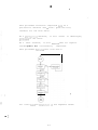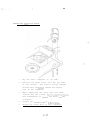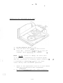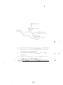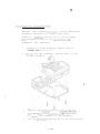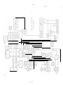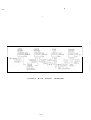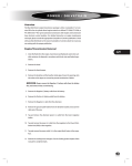
1
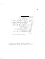
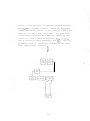
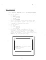
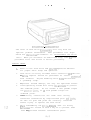
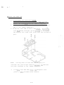
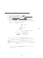
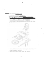
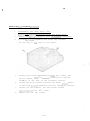
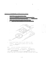
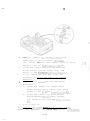
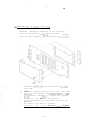
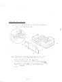
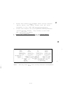
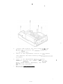
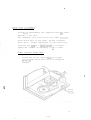
JULY I.980
FSOlSO5i
REV. 1
TABLE OF CONTENTS
1.
SPECIFICATIONS
l-l
2.
THEORY
2-1
3.
BLOCK DIAGP&m & SCHEMATICS
3-l
4.
FLOPPY QUICKCHECK
4-l
5. .
TROUBLESHOOTI’NG
GUIDE
5-l
6.
DISASSPMELY/REASSE:.!BLY
6-1
7.
ADJUSTllESTS
7-1
8.
PARTS
8-l
9.
APPENDIX
10.
INDEX
OF
LISTS
OPERATION
9-1
10-l
.
l-1
TECIip!ICAL
1.
SPECIFICATIONS
Uses ANSI standard Sk inch diskettes in a
soft sectored format.
2.
3.
40 tracks at 48 TPI track.density.
Sinqle density (FM), single sided recording.
4.
Over 905 bytes storage per diskette.
5.
709 sectors of 128 bytes each.
6..
Mininum
data access time: 236 milliseconds.
7.
Averaye
data transfer rate: 6000 bits per second.
8.
Automatic
. 3.
stand-by
capability
(built
in
microprocessor).
Up to four Drives can.be daisy chained to a single
400/800 Computer Console (w/minimum 16K RAM)
!
via select switches at the rear of the Drive.
10.
Drives directly interface with the ATARI 400/800
Computer Console (16K RAM) or indirectly through
the ATARI 850 Interface Module or 820 Printer.-
:
l-3
t
I
2-l
THEORY OF OPERATION
The ATARI 400/800
Computer Console with 16K of RAM
installed connects directly to the 810 Floppy Disk
The Drive may also be daisy chained through
up to
Drive.
the 820 Printer 6r the 850 Interface Module.
four Disk Drives can be connected to a single Console.
Refer to the Disk Drive Operators Manual for installation and oDerating
instructions.
I
,
,
2-3
.-
.
.
The ATARI 810 Floppy Disk Drive consists of the
following
*
*
’
major
sections:
Data Input/Output and Manipulation
Data Interface
* .Read/Write and Erase Heads
* Stepper Motor and Logic
* Diskette Drive Motor and
l
Power
supply
2-4
Logic
DATA INPUT/OUTPUT AND MANIPUWTION
SECTION
Data, control commands and a VCC/RDY signal from the
Computer Console enter the Disk Drive through cithcr
of the two serial I/O connector jacks at the rear of,
the Drive chassis.
Each of the three main signal input lines are buffered
for,statlc protection an&to reduce power consumption
on the 800 I/O lines.
Data is sent by the Console in serial format, with
.
checksums
accompanying
the
2-5
data
for
validity
verification.
.
The Drive’s PIA is primarily a buffering and signal
formatting
device, with no decision making or compucapability.
tational
It
is
responsible
for
the
following:
*
Applying the Console’s serial outputs to the
Data 2nd Address Busses when requested by the
Drive’s Microprocessor Unit (NW).
*
Assisting in the control of the Read/Write
and Erase fiead position by buffering
commands
sent to the Stepper Motor Logic.
*
Assisting in control of the Diskette Drive
,Motor Logic.
*
Providing 128 bytes of R&M for temporary
storage of status inforrnltion and data sent by
the Data Interface Section for application
to the HP".
2-6
-,
.
.
The MPU rjrovides the.primary decision making and
.
cocputational capabilities for the Disk Drive. The
Drive’s ?:PV is responsible for the following:
*
Controlling data transfers, through its
control over the Conmon Data and Address
Busses.
*
Intfr?retinq
and controlling the accon,plishment
of Console commands (temporarily stored
in FLXM) and Disk Drive operating instructions
(permanently stored in ROM).
*
Controlling the Stepper, Disk Drive and llotor
Logics,
which are buffered by the PIA.
The Drive’s ROM contains specific operating instructions
used by the CPU to accomplish a variety Qf-functions.
These functions include telling the Disk controller
.
(1771-01) what task to perform.
The Drivs’s RXY is used by the CPU for temporary storage
of both data and system information.
2-7
.
The Drive’s Data Output Buffer transfers the
formatted data through the PIA to the’Data (out)
line going to the Computer Console.
2-8
.
1
.
The Drive’s Power c’p Logic circuit resets the !&PU,
PIA and Data Interface Section whenever the Disk Drive
is turned on. The RESET references the electrical
circuits to their starting conditions. Additionally,
the Power Vp Logic circuit locks the Data Output
Buffer off during a short period when the Drive is
turned on.
This prevents random pulses generated by
. the Drive’s circuitry (during the initializing period)
from being sent to the Console.
The Drive’s Clock circuitry generates both a crystal
contolled 1 MHz. and a 500 KHz. clock signal.
The
1 MHZ. signal is used by the Data Interface Section.
The 500 KIIz. signal is used both as a clock signal to
the MPU, and to tjme data exiting from the Data Input/
Output and Manipulation Section into th&Data Interface
Section.
2-9
.
DATA
INTERFACE
SECTION
7
The major element of the Data Interface Section is a
Floppy Disk Controller (FDC).
specialized
microprocessor.
the following activities:
The FDC is a highly
It-is responsible for
*
Combining data, timing and data validity
pulses into the serial format to be recorded.
*
Separating the above and Troviding "he otitput
data in parallel during a read qeration.
* Controlling the IGrite and Erase LoTic circuitry
during a write operation.
2-10
;
*
Genrratinq
the data validity codes (called
Cyclic Redundancy Chpcks - or CXC’s) during a
write
read
operation, and checking them during a
operation.
The Drive’s Write and Erase Logic circuitry is ccntrolled
Initially,
by, and receives its data from the FDC.
Data Gate converts the leading edge of each pulse
the
(data, clock, etc.) into a single correanqnding change
of si::ned level. These levels then determine the polarity
of the Drive’s currents applied to the Read/:irite Head
through the High and Low level Drives,
limits the write currents.
2-11
The Write Driver
.
The Data Gate converts ach pulse’s
lending edge iilto a logic level
change, as shown.
Basically, this is the signal applied to the head during a mite
operatim. The high levels out of the Data Gore turn on the High
level Driver, and fhc low levels turn an the Low level Driver.
The Write and Erase Gate turns on both the Write and
Erase Drivers during a write oneration, and turns them
off during a read operation.
The Erase Driver drives
the Erase Head durinq a write operation.
See the Read/
wrrte and Erase Head discussion for further information.
2-12
.
Major elements of the Drive’s Read Data Conditioning
circuitry
*
*
are:
Pifferential Amp - Initial amplification of
,
*
Read/Write Head signals.
L
Differentiator - Squaring up the two differential amp outputs.
*
Zero
Crossing
Detector
- The singleoutput
changes level whenever the two ,180
out-of-
phase input signals cross their zero axis
coincidentally (eliminates false pulses caused
by Read/Write Head signal decay, rather than
intentional signal level changes).
*
Symmetry Amp - Ensures exact zero’referencing
*
Time Domain Filter - Trims and further shapes
of
the signal.
the signal.
*
Signal Gate - Produces a single pulse out for each
logic level transition.at
its input.
This results
in the reproduction of the original FDC signal.
2-13
During a read operation the Read/Write Head produces
two 180
out-of-phase signals.
These are very weak,
highly distorted versions of the original signals produced by the Write Logic Data Gate.
The Read Data
Conditioning circuitry must amplify, square up and
filter the read signals to reproduce the origiqal
This reserial string of bits produced by the FIX.
produced signal is returned to the FDC by the Read
Data
Conditioning
circuitry.
2-14
,
.
Two 180’ out-of-phase sinnals zre
generated by che’head du;ing a read
operation and amplified hy the
Di,ffercntial Amplifier.
The Differentiacor squares the two
out-of-phase signals.
The Zero Axis Crossing Detector
provides a single output, further
squared and now without any signal
decay effects.
The Time Domain Filter provides a
signal with very sharp leading and
trailing edges.
rl l-l n
l-l n
2-15
The Pulse Rfgeneraror converts each
logic level change into a single pulse,
recreating the original signal produced
by the WC during the write operation.
.
The Drive’s Write Protect circuit senses
the presence
or absence of a special notch in one side of the diskette
casing.
R write protected diskette’s notch will be
covered with an opaque tape.
The circuit is basically
an LED/photo transistor sensor, whose’ output is buffered before being applied to the FDC.
With an unprotected diskette, the ser.sor signal allows
the FDC to write data onto the diskette.
2-16
.
.
.
STEPPER MOTOR AND LOGIC
.
The Stc?p~er Motor is a four phase motor with a 3.6"
rotor rotation per step.
POlf.5,
360°
The motor has a total of 100
providing 100 rotor steps for the motor’s full
rotation.
Each step change in the motcr is w-a&slated;
through a steel band connection, to a single track
change far the Read/Write and Record Bead assembly. ,The
diskette is divided into 40 tracks, so-the full range
of the Stepper !.:otor
is not used.
The Stepper Logic is controlled from the PIA.
The
four
PIA signals are logic levels acting as the Stepper
These levels, in their
Motor's foilr phase inputs.
various possible combinations, drive the Stepptir Motor to
reposition the head assembly from track to track.
The Stepper
Motor is supplied with a nominal 3 to 10 VAC
fron the Pcwer Supply.
2-17
.
-
,
DISKETTE DRIVE MOTOR AND LOGIC
The Diskette Drive Motor is a DC motor that indirectly
drives the diskette. The motor includes an internal
tachometer, whose output is monitored in the Tach Fcedback circuit.-’Variations in motor speed, as sensed by
the Tach
Feedback circuit, vary the current supplied
to the motor.
Diskette speed is set to 290 RPM *l%.
Motor rotation is translated into diskette rotation
via a pulley (attached to the motor ihaft), a drive
belt and a flywheel attached to a diskette drive spindle.
When a diskette has.been inserted into the Disk Drive,
and the front door has been latched closed, the diskette
is centered and clamped to the spindle by a clutching
cone assembly.
Whenever the Diskette Drive Motor is supplied with power,
the Dri,vc’s
BUSY lite (LED) is turned on.
2-18
.
DISK DRIVE SELECT
h double "Single pole - Double throw" switch gives
the Disk Drive operator the ability to assign a number
to, and therefore a code for addressing, each of.up
to four Drives that could be daisy chained together.
The switch is accessible at the rear of the Drive
chassis.
The switch settings are read by the Drive’s
MPU through the PIA.
2-19
POWER
SUPPLY
An external step-down transformer is supplied with each
Drive.
The 120 VAC line Power is dropped to 9 VAC by
transformer. This 9 VAC enters the Drive through the
"PW7" jack at the back of the chassis.
the
Turning the Drive’s front panel "PWR" switch ON applies
the 9 VAC to a full wave bridge rectifier.
The Power
Supply provides the following:
*
The unregulated 9-10 VDC Diskette Drive Motor
*
SUPPlY.
A regulated +5 VDC.
*
*
A regulated +12 VDC (initially produced by a
_ voltage doubler circuit).
A
zener
voltage
regulated -5 VDC (also produced by a
doubler
circuit).
A "PWR OX’ lite (LED) is turned on through the -5 VDC
section of the supply.
2-20
.
READ/WRITE AND ERASE HEADS
A magnetic head converts electrical currents into
magnetic fields, and vice-versa. The Read/Wr’ite
Head consists primarily of bo ferrite core halves,
wound with a centerta>Ped
coil.
The centertap is
connected to the regulated +5 VDC from the Power
One end of the coil is connected to the
SUPPlY.
High level Driver, and the other end to the Low
level
Driver.
WRITE OPERATION
Each logic level causes current to flow in one half
of the coil, with a high in one direction and a low
in the other.
These currents ’set up corresponding
magnetic fields in the core halves, with a hi$h represented by a field in one direction, and a low by
.
a field in the opposite direction.
When the ferric oxide coating on the diskette is win
contact with the head, it completes thr magnetic path
between the core halves.
In response to the change
in direction of the magnetic field (logic level change)
passing through the diskette’s coating, the oxide
particles
realign
themselves.
Particle
aliqnmcnt
in
one direction represents a high level, and alignment
in the other direction a low level. ’
2-21
.
/. .
TRACK
I5
TRACK 1
RCAD/WRITE
tl~hD BAP
.ol3u
.
I
.336"
TRACK 13
%%TlCHd
During a write operation, the magwtic fields coupling
through the diskette print a relatively wide C.013") path
of aligned particles.
In order to prevent one reco;ded
track from interfering with either the next inner or next
outer track, a blank space,
between
tracks.
called a guardband, is created
The. Erase Head creates these guardbands.
It straddles the Read/Write Head in such a way that just
after l.036") the data is written onto the diskette, the
Erase Head "tunnel" erases the track width down to .012",
leaving . 008" quardbands
READ
between tracks.
OPERATION
During a read operation, the very small fi*elds existing
due to particle alignment on the diskette couple through
the head core halves.
The diskette is rotating, causing
the specific field being felt in the core halves to change’
for each change in particle alignment tie. change of recorded logic level). The changing fields in the core
halves generate corresponding currents in the head coil
windings.
It is these very small signals that are applied
to the differential amplifier.
2-27.
.
.
DISKETTE FORMATTING
The specific arrangement of information recorded onto
a diskette is called the diskette format.
Unless a
Master Diskette j-3 to be used, the diskette must be
initially formatted with a Disk Operating System (DOS)
software
program.
The DOS software divides the diskette into 19 pie-shaped
slices, 18 of which are called sectors. These are not
the same as the "709 FREE SECTORS" referred to when
you list the directory of a disk.
Because
the
diskette
division is accomplished totally through software, this
process is called "soft sectoring".
The 18 sectors are
equal in size, but the 19th (very narrow) slice acts as
an index to defi’ne the start of each of the 40 tracks.
3
14
7
c?J
I
DISK TURNS
IN THIS PIAECTION
2-23
.
All 40 tracks receive the same formatting as follows:
2-24
.
*
256
1
bytes
00
byte
FC (index mark)
11
bytes
00 or FF
bytes
byte
00
FE
byte
Track Number (00 thru 27) (i3E.u)
byte
00
byte
byte
Sector Numb’er (01 thru 12) (HEX)
byte
00
,
CRC byte 2
byte
bytes
CRC byte 1
00
or
11
6
bytes
FF
bytes
00
byte.
FB (data address mark)
bytes
Data (FF for blank fill)
byte
CRC byte 2
byte
CRC byte 1’
bytes
00 or FF
Cyclic Redundancy Checks (CRCs) arc generated in the.
Drive’s Floppy Disk Controller (FDC) during a write
The FDC uses the recorded CRCs during a
operation.
read operation to verify the data.
CRCs are similar
in function to the checksums used between the Computer
Console and the Disk Drive’s MPU.
*
Appear only once per track for indexinq.
**
Repeated 18 times per track, prbducinq the
full 18 sectors.
2-25
On the following pages are block diagrams.and
schematics
for the Disk Drive.
Further understanding
of the system’s operation can be obtained by comparing
these.
3-1
I
s
I
I
IL!
- 1
3-3
._
.
r----------?-+--
n
=--+A
.-\-
,
----.T-
.
,
$$=J
------II
I
---
1
/
3-7
.
--
7
4-l
.
*
This procedure should he completed both as a
pre-service checkout and a final (post-service)
checkout for the Disk Drive.
As a pre-servjce
probl.emS
checkout, it will assist in identifying
in the Drive.
As a final checkcut, it will ensure that all repairs
and alignments were successfully
completed.
This procedure follows this flow chart:
All tests must be completed.in
:
h-3
the sequence shown.
.
The following are required to perform these
procedures:
A.
Atari 400/800 Computer Console with a
BASIC cartridge and minimum 16K RApn. installed.
B.
I/O cables and Console/Drive power packs.
C. TV.
D.
E.
Master Disk File Manager diskette with
-writeprotect notch taped.
. ,
Blank scratch diskette (not write-protected).
F.
Pterecorded
sample diskette with DOS and
sample programs recorded on a known "good"
Disk Drive.
I
SETUP
1.
Connect the Drive to the Console, and connect
2.
both to power.
Turn the Dr.ive ON and wait for the HUSY lite to
go off.
Ii BUSY lite does not come on and then go off,
recheck
connections. then refer to the Troubleshooting
Guide.
BOOTING
TEST
1.
Insert A blaster Disk File Manager diskette into
the Drive and close the Drive’s door.
2.
Turn the Console OFF, then ON.
Verify that data
is transferred from the diskette to the Console
PAM (turn up the TV sound and listen for the
"buzz . ..buzz...buzz...etc.’
about 10 seconds).
, this should take
When completed, the TV screen
should display the word READY.
3.
If the TV displays any ERXOORS or does not show
If the
READY very shortly, repeat step 2.
system still will not "BOOT UP", recheck your
4-4
1
!
\
Console/Drive
system and hooku? for misconnections
or gross equipment failures.. If none are found and the
system continues to ERROR, refer to the Troubleshooting
Guide in this manual.
4.
When the system has booted,
a.
type DOS (Disk Operating System)
b. press the RETURN key
Verify that the DOS nfnu appears on the TV screen.
5.
Refer to the Troubleshooting Guide if you encounter
an
ERROR
on
TV
the
screen.
WRITE PROTECT TEST
This test must be completed with the write-protected Master diskette
installed.
The TV screen should
be displaying the DOS menu from the Booting Test.
1.
At
a.
b.
type I (capital letter)
6
press RETURN
c.
type 1 (number one)
d.
press RETURN
e.
type y
press RETURN
f.
2.
the Console:
t
Verify that,the TV screen displays ERROR-144.
If it does, the write protect circuit is operating
correctly,
go on to step 3.
If it does not:
a.
Repeat Step 1 again.
b.
If the ERROR-144 still does not appear,
refer to the Troubleshooting Guide.
4-5
3.
Remove the Master diskette from the Drive.
FORI’ATTING TEST
CAUTION:
The forxatting
of a diskette.
operation erases the contents
~ .
This test’must be completed with the DOS from the
Master diskette still stored in the Console RAM.
1. Insert a non-write-protected scratch diskette into
the Drive and close the door.
2.
At
the
Console:
a.
press SYSTEM RESET
0.
c.
type DOS
press RETURN
d.
type I (capital letter)
e.
press
f.
type 1 (number
press RETURN
g.
h.
i.
3.
RETURN
one)
type Y
press RETURN
Verify that after about 45 seconds OE formatting the
Drive’s BUSY lite turns OFF and no ERRORS have been
displayed on the TV screen (refer to the Trouble-
pres
shooting Guide for any ERRORS).
4. At the Console:
a.
type A
b.
5.
6.
RETURN
c.
press RETURN
Verify that "709" or "FREE SECTORS 709" is displayed
at bottom of screen.
If not, refer to the Troubleshooting
Guide.
Press RETURN to get back to "MENU"
4-6
.
WRITE
VERIFICATION
This
1.
2.
test nust
immediately
follow
the FOWlATTIXG
TEST.
At the Console:
a.
type Ii
b.
press FaTURN
c.
type Y
d.
press RZT"mi
Verify that the TV screen displays SELECT ITEM
after a short period of time.
If it does not,
refer t’o the Troubleshooting Guide.
3.
4.
At the Console:
a.
type A
b.
press RETUW
c.
press RETURN
Verify that the TV screen displays DOS SYS
and number of sectors used, followed by the
number of sectors remaining.
If it does not.
If the second attempt fails,
reseat the procedure.
refer to the Troubleshooting Guide.
I
-
f
DOS
SYS (number of sectors used)
(number of sectors
remaining)
4-7
.x;
.
5.
Delete the file as follows:
At the Cqnsole:
a.
1.
2.
c.
RETURN
t’ype D
3.
press
4.
5.
-
press RETURN
6.
b.
press
RETURN
type DOS.SYS
w= y
press RETURN
Z.
After a "SELECT ITEM” appears, at the
1
ty?f A
-2.
press
RETURN
-3. press RETURN
Console:
Verify that the TV screen indicates that there are
709 free sectors remaining.
6.
Remove the blank scratch diskette from the Drive.
.
4-8
COMPATADILITY
TEST
This test verifies that the Drive can read
programs from s diskette recorded on a known
"good" Drive.
1.
2.
3.
Insert a sample diskette’into the Drive.
Turn the Console OFF, then ON.
Verify that after about 10 seconds, the TV
screen displays READY.
4.
5.
At the Console:
a.
type DOS
b.
press
RETURN
Verify that the DOS menu appears on the TV
screen, indicating that the diskette data was
correctly loaded into the Console RAPI.
6.
a.
b.
7.
Refer
to the Troubleshooting Guide in case of any ERRORS.
At the Console:
type A
press RETURN
press RETURN
c.
Verify that the Drive’s BUSY lite comes ON
as the Drive loads its directory listing
.
into the Console.
The directory’should appear
on the TV screen.
8.
Choose a pr,ogram You wish to load.
At the Console:
a.
press RET"PJ\I
b.
d.
type R
press RETURN
type LOAD "D:NAME
e.
press RETURN
C.
OF PROGRAM"
4-9
u
9.
Verify that the Drive’s BUSY lite comes on
as the Drive loads the selected program.
After
several
seconds, the word READY should appear at
the top df the screen.
If not, refer to the
Troubleshooting Guide.
1.0. At the Console:
a.
type RUN
b.
press
RETURN
Verify that the selected program runs correctly.
If it ERRORS, refer to the Troubleshooting Guide.
I-10
.
5-l
PO551
-..-a?+
1.
BLE
CDRRECTIIVE
CAVSE
ACTlDEJ
- ....-*e4
--na.-.j
DRIVE WILL NOT
A.
DEFECTIVE TRANSFORMER
A.
REPLACE TRANSFORMER
TURN ON
B.
E L E C T R I C A L MALFUNC-
3.
REPLACE AND/OR
TlON - P O W E R S W I T C H /
SIDE
PCB,
TROUBLESHOCT
PCB(S)
POWER SUP-
P L Y / R E A R PC0
2.
DRIVE WILL NOT
A.
TURN OFF
3.
DISKETTE DOES
D E F E C T I V E SIDE A N D /
A.
OR REAR PCB
A.
NOT TURN
REPLACE OR REPAIR
PCBS
D R I V E B E L T HAS FALLEN
A.
OFF FLYWHEEL/PULLEY
REPOSITION OR REPLACE
DRIVE BELT
OR IS BROKEN
B.
D R I V E MOTOR DEFECTI
C.
V
3.
R E P L A C E D R I V E ,?OTOR
C.
ADJUST OR REPLACE
E
CLUTCH CONE NOT
CLAMPING DISKETTE
D.
ELECTRICAL
MALFUNC-
TION - DRIVE MOTOR
CIRCUIT,
REAR PCB
5-3
CLUTCH CONE ASSEMBLY
a.
REPLACE AND/OR
TROUBLESHOOT PCB
SYMPTOM
-
POSSIBLE CAUSE
-
- -.??FE!
-
-
C O R R E C T I V E ACTlON
-~-
II
4.
DISKETTE SPEED
A : D RDRIVE
I V E MMOTOR
O T O R TTACH
ACH
SLOW OR VARYVARY-
A.
LINE OUT OF PLACE
CONNECT GREEN MOTOR
H A R N E S S LE.AD TO CENTER
ING
ING
TERMINAL OF WRITE
PROTECT HARNESS
0.
WRITE PROTECT
6.
CIRCUIT BAD
C.
DRIVE BELT INCOR-
REPLACE TRANSPORT LEFT
51 DEPLATE
c .
RECTLY TENSLONED
A D J U S T DRIVE B E L T
TENSION
D.
DRIVE BELT STRETCHED
0.
REPLACE DRIVE BELT
E.
ELECTRICAL MALFUNC-
E.
REPLACE AND/OR
.\
TION - DRIVE MOTOR
CIRCUIT,
F.
TROUBLESHOOT PCB
REAR PCB
SPINDLE BEARINGS
F.
FREEZING
5.
DISKETTE WON T
A.
BEARISGS
EJECT MECHANISM
A.
EJECT
E
J E C T WHEN
W H E NFRONT
FRONT NEE
NEEDS
D S A DADJUSTING
JUSTING O
OR
R
DCOR IS OPENED
REPLACE SPINDLE
ADJUST OR REPLACE
MECHA.NISM
IS BROKEN
1
3.
CLUTCH
CONE-TO-
SPINDLE CLEARANCE
(D
O O R
O P E N) T O O
I
I
SMALL
5-4
0.
SHIM THE CLUTCH
CONE ASSEMBLY
.
.
.
CCRRCCTIVE
6.
FRONT DOOR
A.
WON T OPEN
DOOR LATCHING
A.
ACTION
ADJUST OR REPLACE DOOR
L A T C H MECLiAN i SM
MECHANISM NEEDS
ADJUSTMENT OR IS
BROKEN
7.
DRIVE/CONSOLE
A.
A.
INCORRECT
SYSTEM WILL
NOT BOOT UP
DR:VE MOTOR SPEED
B.
A D J U S T DRtVE M O T O R
SPEED
CAN T FIND TRACK 00
0.
ADJUST TRACK 00 STOP
SETSCRE.4
c.
ELECTRICAL
TION,
MALFUNC-
C.
SIDE AND/OR
REFLACE A N D / O R
TROUBLESHOOT PCB(S)
R E A R PCEtS1
D.
STEPPER MOTOR MAL-
D.
R E P L A C E STEP?ER M O T O R
E.
COMPLETE
FUNCTIONING
E.
RADIAL TRACK MISALIGNMENT
8.
RADtAL T R A C K
ALIGNMENT
F.
BAD HEAD
F.
REPLACE HEAC ASSEMBLY
OCCASIONAL
A.
DAMAGED DISKETTE
A.
REPLACE
READ ERRORS j
6.
DIRTY OR MAGNETIZED
8.
CLEAN AND DEMAGNETIZE
HEAD
ALL TRACKS:
C.
DISKETTE
HEAD
WGRN OR DIRTY HEAD
PRESSURE PAD
5-S
C.
REPLACE HEAD PRESSURE
PAD
.
SYMPTOM
POSSIBLE
CAUSE
-I--- -a-.---
D.
OVERSTRESSED PRESSURE
CORRECTIVE ACTION
-___
--.. --.TzzzZ~2~
0.
REPLACE SPRING OR
PAD ARM SPRING
I N N E R TRACKS:
A.
DRIVE MOTOR SPEED
H E A D AisEMBLY
4.
ADJUST DRIVE MOTOR
SPEED
INCORRECT
0.
E L E C T R I C A L MALFUNC-
B.
REPLACE AND/OR
TROUBLESHOOT
TION I N REAO C I R C U I T
PCB,
R E AR
S I D E PC8 O R
.
HEAD.
(CHECK
FOR
SLOW
Qla2 O R 2104 O N S13E
i
PCB.)
OUTER TRACKS:
A~
DRIVE MOTOR SPEED
A.
ADJUST
INCORRECT
B.
DRIVE MOTOR
SPEED
E L E C T R I C A L MALFUNC-
0.
R E P L A C E ANDiOR
TION IN READ CIRCUIT
TROUBLESHOOT REAR
PCB,
SIDE PCB OR HEAD.
(CHECK 9 1 5 5
V A L U E
O N
R E A R PCB.)
9.
DRIVE WON T
A.
DAMAGED DISKETTE
A.
REPLACE
DISKETTE
WRITE DATA
B.
ELECTRICAL MALFUNC-
B.
REPLACE
AE:D/OR
T I O N IN W R I T E C I R C U I T
TROURL ESHOOT R E A R
PCB,
5-G
S I D E P C B O R HEA
IO.
VAF: I OUS ERROR
CODES DURING
A.
E L E C T K I C A L O R ME-
f
A.
CHECK TO ENSURE
D I S K E T T E II S
S NNO
OT
CHANICAL M
MAALLFFUUNNCCTTIIOONNSS ji
WRITE-PROTECTED
OPERATION
R E P L A C E 2105
REPLACE AND/OR
TROUBLESHOOT PCBS,
I
TRANSPORT
11.
DR,lVE
DRIVE MOTOR SPEED
ADJUST DRIVE MOTOR
INCOMPATABILITY
INCORRECT.
SPEED
6.
RADIA
A LL T R
RA
AC
CKK MISMIS-
12.
COMPLETE RADIAL TRACK
ALIGNMENT
E
i
AL1GNMEN.T
DRIVE WRITES
MALFUNCTIONING WRITE
i
I *.
CHECK WRITE PROTECT
O N T O WRITE-PRO-
PROTECT CIRCUIT
a
LED/PHOTO-TRANSISTOR.
WIRING HARNESS CON-
TECTED DISKETTES
NECTIONS.
REPL.ACE
TRANSPORT LEFT
SIDEPLATE.
I
5-7
.
6-l
.
.
I
.
DISASSE?!RLY
AXD XEASSEilDLY
The level of Disk Drive disass,embly will vary with the
specific
problem
encountered.
which are thexselves
case."
Some procedures list steps
procedures: ie. "Disassemble the Drive
When you encounter an underlined step, turn to that
procedure first and follow it before proceeding.
SPECIAL
1.
2.
NOTES
Refer to the Disk Drive and 400/800 Operators Manuals
for proper Drive setup and operation.
Disk Drive circuitry includes static sensitive NOS devices.
All
Drive
work
repairs should be performed at static ?rotectei!
surfaces. Anyone handling Drive PC8s should wear
a grounding strap.
3.
To
4.
Overtightening screws will strip the.threads on plastic
and aluminum parts.
Do not exceed 6 inch pounds torque
prevent thread damage, use only the specified screws.
for plastic’parts,
aluminum
5.
Internal
or 10 inch pounds torque for
parts.
wiring
connections
are
made
with
wiring
harnesses terminated by nonpolarized pins a&jacks.
Be sure all pins and jacks are correctly. installed
before trying to operate the Disk Drive.
6.
Vhen reassembling the Crive, ex.ure
’that all wiring
haixesses are routed in such a way as to prevent them
from being pinched
between
reassembled
parts.
.
DISASSEMI3LY FLOW CHART
-
Identify the level of disassembly
required and complete the sequence
of steps indicated above.
5-4
.
DISASSZICBLY
-__.-DISASSEMBLING THE DISK DRIVE CASE
WARNING:
Unplug the Drive’s AC transformer
BEFORE opening the case.
from AC power
’;
I
1.
With the Disk Drive rightside up on a suitable work
surface, .locate and remove the four adhesive screw hole
covers on the tophousing.
2.
Locate and remove the four screws securing the top-
3.
Lift the tophousing from the base, and set it aside.
housing to the base.
CAUTION:
The record/playback and erase head sub-assembly
is extremely sensitive to magnetic fields.
DO NOT "se
magnetized tools or articles when working inside the
Drive case or near the Drive transport.
6-5
.
REMOVING TIX CO&WON BASEPLATE
NOTE :
Removal of either the side PCB, rear PCB or
Crive transport requires removal of their common baseplate
from the Disk Drive base.
1.
Disassemble the Disk Drive case.
2.
Disconnect the AC transformer power cord from the
3.
PWR jack at the rear of the Drive chassis.
Disconnectany I/O cables from the I/O CONNECTORS
at the rear of the Drive chassis.
4.
Locate and remove the five screws securing the common
baseplate to the base.
.
I
5.
Carefully lift the basep.l.ate from the base.
Note
that each of the bosses in the base is topped with
a rubber washer.
NOTE:
As you lift the baseplate from the base, the front
Remove the
coverplate will lift out at the same time.
coverplate from the baseplate-and set it aside.
6.
Place the baseplate
work
on a suitable static protected
surface.
6-7
REMOVING TIir: SIDE PCB
1.
Disassemble the Disk Drive case.
2.
Remove the cor?mon baseplate from the Drive base.
3.
Locate and disconnect the write protect wiring
harness ( nonpolarized - black, green, (blank),
red, black) from the side PCB.
4.
Locate and disconnect the stepper motor wiring
harness (nonpolarized
- black, white, red, green,
brown) from the side PCB.
MOTE: See Appendix for alternate wirinq harness arrangement.
6-8
5.
Locate and LE~OVE the three screws securing the
side PCB and its center ground bracket to the common
baseplate.
6.
Grasp the side PCB at both its front edrje and
its upper rear corner. Lift the PCB straiqht up
to disengage its rear jack from the row of pins
.
NOTE :
You may have to rock the PCB slightly to ~vercane
the jack-to-pin tension between the two PCBs.
7.
Place the side PCB on a static protected work surface.
6-9
REMOVING
1.
THE
RF SHIELD
(S I D E PCB)
Disassemble the Disk Drive case.
2.
Remove thf common baseplate from the Drive base.
3.
Remove the side PCS from the common baseplate.
4.
Locate and carefully straighten the three tabs’
securing the RF shield case halves together on
the side P6B.
CAUTION:
Excessive bending of the metal tabs will
break them.
DO NOT bend the tabs anymore than
necessary.
5.
Locate and remove the two scrfws securing the case
6.
Ccnefully
halve; to the ground bracket and PCB.
disengage the cask halves from each other
and the PCB.
Set the case halves aside.
6-10
.
3.
the-k_-_Driv- case.
Remove
the
common
baseaiate
from the Drive base.
--_
Rfnovf the side PCB.
4.
Grass the transport securely,.tip
5.
upside down, and place it on a suitable work surface.
Locate and remove the four screws that sec& the
1.
2.
Disassemble
the assembly
transport to the baseplate.’ The screws are accessible
only from the underside of the bascvlate.
.
CAUTION:
The transport provides critical mechanical
alignments necessary for proper Disk Drive operatiofi;
Be very careful not to jar or damage the transport or
any of its associated sub-assemblies and components.’
6.
Place the transport and baseplate on a suitable
work surface.
6-11
REMOVING THE REAR PCB
-
2.
Disassemble the Disk Drive case.
Remove the common baseplate from the Drive base.
3.
Remove the side PC8 from the common baseplate.
1.
4. Locate and remove the four screws securing the rear
PCB to the common baseplate.’
5. Grasp the rear PCB on both side edges.
. 2
Carefully
lift the board straight up far enouqh to disengage
the board’s two right side jacks from the six device
pins.
NOTE:
You may have to rock the PCB slightly to
overcome the jack-to-pin tension between’the
PCB and
the pins attached to the common baseplate.
6.
Lift fhe rear PCB away from,the
baseplate and
place it on.a suitable work surface.
6-12
1.
2.
the Disk
- Drive case.
I?EI~~OVF the comw~n__-__--basc.nlate from the Drive
--__._I
3.
Rx~ove the side PC’S from the>comon
4
Disnsscmhle
. +move
5.
base.
baseplate.
t h e rear PC S .Lron the cannon baswlate.
Locate and rfmovii the sinqle screw securing the
device (either transistor Q113 or voltage regulator
AlOR) to the c~rrm~n
baseplate.
.
BASEPLATE
NOTE:
Ii you are removing Q113 you.should find an
insulating plate between the back of the device and the
cOmmOn baseplate. Also, both Q113 a&A108 use the
common
baseplate as a heatsink.
Each device and Q113’s
insulating plate Bhould be coated with heat transfer compound.
6.
Lift the device (Q113 or A1081 from the baseplate
and set aside.
6-13
I.
.
1.
Disassemble the Disk Drive case.
2.
Remove the common baseplate Erom the Drive base.
3.
Remove tt.6 Drive transport from the so;nnon
4.
Carefully lay the transport on its side.
5.
Locate ana remove the drive belt.
baseplate.
NOTE: TO remove the drive belt without stretching or
the large flywheel (naked for
d a m a g i n g irotate
t,
strobe) while easing the belt off the outside edge of
the flywheel.
6-14
*
.
1.
2.
3.
4.
5.
Disassemble
the Disk Drive case.
~-~.___RQ~OPE the ----_
cornnon baserilate from the Drive base.
RCIIIOVC- the Drive transsort from the ccmmon baseplate-1
Remove the drive belt from thetransport.
Locate and disconnect the single blac!k ground lead
coming from the drive motor wiring harness and going
.
6.
While supporting the drive motor with one hand, locate
and remove the two screws securing the drive motor
to the transport casting.
7.
Separate
the drive motor from the casting.
6-15
.
,.
R E M O V I N G T!IE C A R R I E R ASSEMDLY
1.
Disassemble the Disk Drive case.
2.
Remove the com~ilon baseplate from the Drive base.
3.
Remove the Drive transport from the common baseplate.
4.
Locate the’head assembly and slide the assembly
all the way to the rear of its travel.
5.
Locate and loosen approximately two full turns, but
do not remove, the two SCICWS securing the carrier
assembly to the rear of the transport casting.
6.
Locate the four screws securing the front paneL bezel
7.
to the side guide assemblies and the transport casting.
Loosen (do not remove) the two bottom screws
approximately four full turns.
8.
Remove the two top screws.
6-16
.
.
9.
Push the door release button at the front of the
transport to disengaqc the carrier assembly from
the door latch.
Lift the assembly far enough to
clear the latch mechanism and release the button.
Lower the door to a resting position.
10.
Now completely remove the two screws at the rear
11.
Pull the top
12.
Carefully,
of the transport casting.
of the front panel
CAUTION :
bezel
lift the carrier assehbly
forward.
out of the transport.
You will have to tilt the carrier assembly slightly
to clear the head assembly!s pressure pad arm.
IDO NOT
lift&e pressure pad arm hisher than it would be lifred
Liftinq
by
-the door arm during normal Drive operation;
the pad arm too far will distort its pressure spring,
changino
the pressure pad’s loading effect on the head.
- - - i
6-17
.
REMOVING THE T?ANSPORT
1.
2.
FLYWHEEL/DRIVE SPINDLE
Disassemble the Disk Drive case.
Remove the common baseplate from the Drive base.
3.
4.
Remove the Drive transport from the comma baseplate.
5.
6.
Remove the carrier assembly from the transport.
_
Carefully lay the transport on its side.
7.
Locate the single screw in the center of the
Remove the drive belt from the transport.
flywheel.
reiiio"~
NOTE :
.
liolding the flywheel with one hand,
the screw.
See the following illustration of the
flywheel/casting/spindle
number andplacenent
relationship.
The specific
of the washers is x important
and helps to determine diskette speed during operation.
DO NOT lose any of the washers you remove during this step.
6-18
.
Diskette
Spindle
Washers
8.
9.
Being very Careful not to lose any washers, hold
the drive spindle with one hand and carefully pull
the flywheel away from the casting with the other hand.
Pull the spindle from the casting.
6-19
RE?,O’:ITG TIE TPANSI’C3.T SPINDLE SXAFT
. 1.
2.
3.
4.
Disassemble
BEARINGS
-
the Disk Drive caa
!?.e!nove the common basgplate frc!n the Drive base.
3emove the 3rive trznsport fror the common baseplate.
5.
Remove the Drive belt from the transport.
3emove t?l& carrier assembly
from the transport.
-
6.
Remove the flywheel and drive spindle from the
transport.
!
7.
The top spindle shaft bearing may have lifted
from the casting when you removed the drive spindle.
If it did nclt, sy carefully pry the bearing out
of the’ casting.
8.
Very carefully push the bottom bearing out of
the casting (push from the top side of the casting,
being very careful not to damage the casting bore).
6-20
. .
Nylon
c1anp
.
5.
Locate the nylon clamp securing the record/playback
.
and erase head I/O wirinq harness to the riqht rear
corner of the casting.
Release the clamp from the
casting.
6.
Push the head.assembly
7.
Drive as it will slide.
Locate and remove the ground lead (black wire from
as far to the rear of the
the drive motor wirinq harness) faston from the rear
of the casting.
6-21
.
8.
Locate the two screws securing the stepper motor
positioning band to the right side of the head
assembly.
Remove the rear scrw, being wry careful not
a.
to crimp or damage the band, and noting the screw
and washer arrangement.
b.
Slide the head assembly carriaqe forward
enouqh to allow you to renove the’front band
SCL-ET./.
the screw
NOTE:
Remove the front screw, again noting
and washer arranqemcnt.
The stepper motor positioning band is very
delicate and very important to the operation of the Drive.
DO NOT-kink or damage the band in any way.
-
6-22
3.
Locate
the two screws
securing
the
carriage
10.
guiderod clanps to the drive casting.
Romooc the two screws and lift the guiderod clamps
11.
away Krom the assembly.
Carefully pry the two guiderods up out of their
locating notches
12.
in the drive casting.
Gently lift the head assembly carriage and guiderods
away from the casting.
head
CAUTION:
fields.
I/O
cable
You will have to feed the
through
the
casting
at
the same time.
The head is subject to external magnetic
DO NOT use maqnetizcd tools or allow the head
tb get near any equipment ?r;ducing strong magnetic fields.
Slide the quiderods Out of the ci!:riag,-.
13.
6-23
RLI:OVI?iG THE STEPPER MOTOR
1.
Disassemble
the Disk Drive
case.
-_
Remove the common basexplate from the Drive
case.
Remove the i>rlve transport from the corcaon baseplate.
2.
3.
4.
Locate the two screws securing the stepper rotor
positioning band to the right side of the h&d assembly.
a.
Remove the rear screw, being very caref,zl
crimp or.d&xage
washer
b.
not to
the band, and noting the screw and
arrangement.
Slide the head assembly carriage forwar?. enough
to allow you to remove the frcnt band screw.
&nave the front screw, again noting the screw
and
washer
arrangement.
NOTE :
The stepper motor positioning band 1s very.delicnte
DO
and very important to the operation of the Drive.
- NOT
kink or damage the band in any way.
6-24
I
.
5.
Locat? the allen-head setscrew securinq
the head position-
ing strap pulley to the stepper motor drive shaft
(topside of casting).
6.
Back the setscrew out about 1 turn (counterclockwise).
.
7.
Remove the band/pulley from the .stepper motor shaft
. .and set it aside.
8.
Locate the
two nuts securing the stepper motor to
c
the casting.
9.
10.
Lay the casting on its left side.
While supporting the stepper motor with your right
hand, remove the two securing nuts.
11.
Carefully separate the motor from the chassis, while
pulling the motor wiring harness out of its chassis
slot.
6-25
.
REASSEMBLY
-
Locate the beginning point
of your reassembly, and follow
the instructions called out
in this flow chart in the
order shown.
6-26
1.
Install a
2.
Lay the transport on its left side.
3.
Position the stepper mqtor to the underside
split
ste:,per
rubber
grommet
on
the
motor wiring harness.
of the tran*pcxt
casting.
.
The motor’s
wiring harness should lie toward the rear
center of the
casting.
.
CAUTION:
The head is subject to magnetization
from external fields.
D O NO T
use magnetiied tools
or allow the head to get near any equipment producing
.
strong magnetic fields.
6-27
. ,,
4.
Install a flatwasher,
and a l/4"
a splitring lockwasher,
hexnut onto each of the two
stepper motor stud bolts projecting through
the top of the casting.
Liqhtly tighten
the nuts.
..
5 .
Carefully install the head positioning
band pulley onto ’the stepper motor drive
shaft (projecting through the top of the
casting).
If the pulley does not easily
slip onto the motor shaft, back the pulley’s allenhead setscrew a little farther out
of the pulley. DO NOT-tighten the setscrew
a t t h i s t i m e .
NOTE :
The stepper motor positioning band is
delicate and VERY important to the operation.
DO NOT
of the Drive. - kink OS damage the band in
any way.
6-28
6.
Carefully position the head assembly, so that
you ca connect the positioning band to
the assembly’s right rear
7.
Install,
corner.
but do not tighten, the rear screw,
splitring lockwasher, and special bracket
washer to hold the Rena section of the
positioning band to the head assembly.
8.
Carefully pull the front section of the
positioning hand forward until its screw hole
is located over the matching screw !lole on
the front corner of the head assembly.
9.
Install,
but do not tighten, the sorew,
splitring lockwasher, and flatwasher to
secure the band to the head assembly.
10.
Gently slide the head assembly back and forth
on its guiderods.
pulley on the
11.
This will center the band
stepper m6tor
shaft.
Tighten the rear band retaining screw.
CAUTION:
1)O
- NOT- exceed 6 inch lbs. torque when
tightening screws into plastic parts.
6-29
.
12.
Use a pointed tool (i.e. X-act0 knife point,
etc.) to hook the small hole on the front
end of the positioning band. Pull forward
.
slightly on the band while tightening the
front band retaining screw.
13.
Slide the wiring harness’ grommet up into the
14.
slot at the rear of the transport castinq.
Attach the transport to the con~mon baseplate.
15.
Attach the common baseplate to the Drive base.
6-30
.
CAUTIONS:
The
is subjectto magnetization
head
from external fields.
DO
NOT use magndtizfd
tools or allow the head to get near sny equipm e n t prac:ucing s t r o n g m a g n e t i c
fields.
The head is also damaged by dirt and oils.
00 NOT touch either the head or the pressure pad
with your fingers.
DO
- NOT
- lift the pressure pad arm farther from the
head carriage than the arm would be lifted during
normal Disk Drive operations.
Lifting the arm
too far will distort its pressure spring,
changing the arm’s loading effect on the head
during
The
operation.
stepper motor positioning band is,..
delicate and very j.mportant to the operation of
the Drive.
DO
- NOT
- kink or damage the band in
any way.
I
6-31
.
1.
Slide the two guiderods into the sides of
2.
the head assembly carriage.
Carefully lower the carriage/quiderods
assembly into position in the transport
casting.
Ensure that the head wiring harness
lies down in the underside of the transport.
3.
Wrap a
small piece of maskinq tape around
the head assembly’s wiring harness, about
3" from the head. Install the nylon cable
clamp over the tape and snap the clamp into
the hole provided at the back of the castinq.
4.
Feed thf wiring harness up through the
rectangular hole at the right rear corner
of the transport casting.
6-32
t
Center (front-to-back) the two hEad assembly
5.
guiderods in their transport casting slots.
Position the two guiderod clar;ps onto the
6.
casting,
over the ends of the guiderods.
Install, but do not tighten, the front clamp
7.
screw including a splitrinq lockwasher.
Install, but do not tighten, .the rear clamp
screw including two male faston terminals
8.
and a splitrinq lockwasher.
Tighten the two clamp screws to 10 incti lbs. torqu?.
9.
-
.
6-33
.
10.
Carefully position the head assembly so that
you can connect the positioning band to the
asse&ly’;j
11.
right rear corner.
Install, but do not tiqhten, the rear screw,
splitring lockwasher, and special bracket
washer to hold the rear section of the
12.
positioning band to the head assenbly.
Carefully pull the front section of the
positioning band forward until its screw hole
is located over the matching screw hole on
the front corner of the head assembly.
13.
.
Install, but do not tighten, the SCP.SI,
splitring lockwasher, and flatwasher to
secure the band to the head assembly.
14.
Locate the allen-head setscrew securing
the positioning band pulley to the stepper
motor driveshaft.
Back the setscrew out
(counterclockwise)
about
l/4 turn.
15.
Gently slide the head assembly back and forth
on its quiderods.
This will center the
ba’nd pulley on the stepper motor shaft.
16.
Tighten the rear band retaining screw.
CAUTION:
00 NE exceed 6 inch lbs. torque when
tightening screws into plastic parts.
6-34
.
.
17.
Use a pointed tool (ie. X-acto knife point,
etc.) to hook the small hole on the front
end of the positioning band. Pul’l forward
slightly on the band while tightening The
front band retaininq screw.
18.
Attach the black ground lead (drive motor
wiring harness) to one of the faston lugs
19.
at the rear of the transport.
Attach the carrier assembly to the transport.
6-35
b
.
TF!E
INSTALLING
1.
TRANSPORT SPINDLE SHAFT BEARINGS
Gently insert either the top or bottomcor
both)
shoulder bearings into the casting bore.
There should be a slight friction fit.
NOTE:
If excessive force is required, you
probably
have
incorrectly
identified
the
bearing.
Obtain the correct bearing before proceeding.
Upper Spindle Shaft
Shoulder Bearing
"I
Transport
Casting Bore
Lower Spindle Shaft
Shoulder Bearing
2.
i?nsure that the shoulder of the bearing is
firmly seated flat against the castinq.
3. Attach the flywheel and drive spindle to
the
transport.
6-36
1.
Lay the transport casting on its side.
Diskette
Spindle
Flywheel-
2.
3.
From the top side of the casting, insert
the diskette drive spindle into the shoulder
bearings.
Assemble the necessary combination of
washers along with the flywheel and screw.
See the illustration for the flywheel/casting/spindle
relationship.
The specific number and placement of the
washers is very important and helps to
determine diskette speed during
6-37
operation.
.
4.
Fran the bottom side of the casting, position
the flywheel, screw and washer combination
over the,bottom of the spindle shaft.
screw
the assembly together.
Torque the screw to
.
6 inch lbs..
5.
Rotate the flywheel and ch&!< for wobble,
runout or binding of either the flywheel or
drive spindle.
Adjust the assembly as
necessary.
6. Attach the carrier assembly to the transport.
6-38
I
.
.
INSTALLING T’:Z CARRIER
CP.UTIONS:
ASSE:,,?L,Y
This procedure requires that you lift
the head assembly pressure pad arm in order
to pdsition its lift arm onto the carrier
assembly.
DO NOT
__
__ lift thc.pressure
pad higher
than it would be lifted by the carrier asseriDly
during normal operations. Lifting the pad arm
too far will distort its pressure spring,
chanqing,the
pad’s loading effect on the head.
The head is subject to magnetization from
external fields. DO NOT use magnetized tools
or allow the head fo qct near any equipment
prbducing
1.
strong magnetic fields.
Ensure that the transport front panel bezel
is tilted forward from both guide assemblies
for extra clearance at the top.
6-39
2.
Carefully lower the carrier assembly into
position over the transport casting.
Lift
the head assembly’s pressure pad arm just
enough to position it onto its carrier
assembly slide area.
3.
Install and slightly tighten the two screws,
splitring lockwashers, and flatwashers at
the rear corners of the carrier assembly.
6-40
.
Dush the bezel back to its norna: position
4.
and install the two top screws.
Tighten the four screws securing the bezel
5.
to the transport.
6.
Latch the carrier assembly closed (down)
at the beze.1.
b
Door
Centered on
Panel Opening
I
7.
Horizontally center the door in the door
opening of the bezel.
8.
Tiqhlxn (10 inch lbs.) the two screws securinq the rear cor,ners of the carrier assembly
to the rear of the trsnspbrt casting.
3.
Press the front door release button.
Ensure
that the door opens and the carrier assembly
lifts the head assembly pressure pad arm.
6-41
10. With the door open, observe the gap between the
to? edge of the diskette drive spindle and the
bottom edge of the clutch cone assembly.
B e sure
a diskette can move in arid out without being
scratched’or
NOTE :
pinched.
The spindle/cone clearance is critical
to ensur& that the diskette is ejected when
opening the front door.
T OO little
clearance
nay cause the back edge of the cone to catch the
edge of the diskette hub hole, preventing the
diskette from being ejected.
Test the ejection
process using a standard diskette.
9- R e t a i n i n g C l i p
Flatwasher
(as many as needed)
--\
/;:
.
11.
To adjust the clearance, compress the clutch cone
into the doorarm, forcing the clutc!i cone shaft up
12.
out of the top of the carrier assembly.
Locate and remove the retaining cliF from
13.
the shaft.
Place another flatwasher over the shaft and
14.
replace the retaining clip.
Release the clutch cone and return to step 10.
6-42
.
.
15.
With the cai-rier assembly open, push the
diskette eject block (right rfar corner)
until it latches into its rear position under
the latch lever.
16.
Close the carrier assembly an6 thep press the
17.
Cheek to sfe that the diskette eject block
release button to reopen the door.’
freely returned tc its forward position when
the carrier assembly opened.
18.
If the block did not return, bend either the
latching lever or the lever lifting arm to
I
adjust the mechanism.
19.
20.
21.
Repeat, ste?,s i5 thru 18 until the diskette
eject mechanism works as indicated.
If necessary, *tall the drive belt.
Attach the tra>sport
to the cornnon bascplate.
.
6-43
.
INSTALLING
THE "RIVE MOTOR
-.
1.
Lay the Drive transport on its side.
2.
Position the drive motor onto the top side
of the casting. The motor’s wiring harness
should exit the notor toward the center
rear of the transport.
3.
While supporting the motor with one hand,
install the two screws, splitrrng lockwashers,
and flatwashers to &?cure the motor tO the
transport.
4.
Torque the tW0 sCrfWS to 10 ir.ch lbs.
5.
Attach the drive belt to the transport.
6-44
.
*
.
1.
Lay the transport on its
2.
Loop the drive belt over the drive motor
s i d e .
drive hub. Carefully ease the belt onto the
flywheel while rotatinq the flywheel.
a
NOTE:
DO NOT stretch or damage the drive belt.
It is primarily responsible for diskette speed
and any variations in diskette speed caused by *
a stretched or damaged drj.ve belt can cause
errors during read and write operations.
3.
Refer to the adjustments section of this manual
and complete the drive belt adjustment.
4.
Attach the transnort to the common baseplate.
K-45
’
.
INSWUJ,INC
4113 (~~~Nsrsux)/~108
-_
(VOLTAGE
REGULATOR)
screw
IF-Bend
Device
Apply Heat
Transfer Cpd.
Lockwasher
$&---Hexnut
1.
Bend the leads of the device you are about
to install as shown above.
2.
If you are installing Q113(transistor):
a.
Apply heat transfer con;mund to both
b.
Place the insulating plate into location
on the common baseplate.
c.
Place the transistor into position on
sides of the mica
insulating plate.
top of the insulating plate.
d: Secure the transistor/insulating plate
combination
to
tht? connon
baseplate
with
a #4-40 x 3/8" PHIL HD. SCREW, shoulder
washer, f4 splitring lockwasher, and a 114
ST2 hexnut.
6-46
.
r
3.
If you are installing A108(voltage
a.
regulator):
Apply heat transfer compound to the back
of the voltage reql1ator.
b.
:
Position the regulator onto the common
I
,
baseplate.
c.
4.
Secure the device to the baseplate with
a #4 x l/4 THD F PFiIL HD. screw.
Attach the rear PCB to the conman baseplate.
6-47
I
.
INSTALLING THE REAX PCB
1.
Carefully lower the rear PC8 into position
Ensure that the
on the common baseplate.
six device legs at the right side of the
baseplate are correctly seated into the two
three-pin sockets on the PCB.
2.
3.
Install and tighten the four screws(#6-32 x
l/4" PHIL HD.) and lockwashers(F6 splitring)
to secure the PCB to the baseplate.
Connect the transport to the common +seplate.
6-48
.
CAUTION:
The transport provides critical mechanical
alignments necessary for proper Disk Drive
operation.
Be vfry careful not to jar or damage
the transport or any of its associatedsubassemblies
1.
and
components.
Carefully set the transport upside down on
a suitable work
2.
surface.
Gently set the transport (upside down) on top
of the transport.
.
3.
Install and tighten the four screws(t6-32 x
l/4" PHIL HD.) and lockwashers(%
to sec"rc
4.
splitring)
the transport to the baseplate.
Set the asse!nbly
rightside up on the work surface.
6-49
.
5 .
Locate
and
connect
the~record/playback
and
erase head I/O wiring harness (shieldedred, (blank), blue and either white, black or black,
white) to the r&r PCS (nonpolarized, X4).
6.
Locate and connect the drive motor/ground
wiring harness (yellow, green, blue, red,
7
.
black) to the rear PC8 (nonpolarized, #3).*
If you removed the side PCB, follow the
procedures to attach the PCB to the common
baseplate.
8.
If you did not remove the side PCB during
disassembly:
a.
Locate and connect the stepper motor
wiring harness (black, white, red, green,
brown) to the side PCB (nonpolarized, #2).
b.
Locate and connect the write protect
wiring harness Iblack, green, (blank),
. red, black) to the side PCB (nonpolarized,
#l).
9. GO on to step 10.
10. Attach th!:s-on baseplate to the
"NOTE:
See
Appendix
for
6-50
Drive
base
2
alternate wiring harness
arranqemant.
; \
I
.
INSTALLING Tlii: RF SIIIl?T,L) (SIDE PCB)
CAUTION:
Excessive handling of the locating
tabs on the shield case will break them.
DO NOT
bend the tabs anymore than absolutely riecrssary.
1.
Carefully psition the case halves on& the
side PCB.
2.
Position
3.
Insta’ll and tighten the two screws 186-32 x
5j16" TRD F, PHIL HD.) to secure the ground
the ground bracket onto the side PCB.
bracket to the PCB and case halves.
4.
LocaCe and bend the three tabs securing the
RF shield case halves together.
5.
Connect
the
side
6-51
P C B t o t h e ccmmn b a s e p l a t e .
INSTALLING THE SIDE PCB
1.
Position the side PCB on the common baseplate
(with rear PCB installed).
\
2.
3.
Gently seat the multipin socket at the rear
lower edge of the side PCB down onto the
pins protruding from the rear PCB.
Install and tighten the three screws (116-32 x
5/16" THD F, PHIL x1.1 that secure the side PCB
and its qjround bracket to the common baseplate.
6-52
*
4.
Locate and connect the stepper motor wiring harness
(black, white, red, green, brown) from the Drive
5.
transport to the side PCB (nonpolarized, ’P2).
Locate and connect the write protect wiring harness
(black, grwn, (blank), red, black) to the side
PCB (n,mpolarized, $1).
6. Attach the common baseplate ~.
to the Drive base.
.
NOTE:
You may also have this wiring harness arrangement.
G-53
.
I’ISTALLING TUE CC?!?,!ON BASEPLATE
-
1.
Ensure that every boss in the base (even
those not used to sfcwe the baseplate1 is
topped with a rubber isolation washer.
2.
Position. the front coverplate onto the
baseplate/transFort/PCB
3.
assembly.
Carefully lower the baseplate into position
in the Drive base, ensuring that the cover-plate
is also correctly positioned in the base.
6-54
a
.
4.
Install and tighten the five screws (6 - l/2"
BT.
PHIL HD.)
securing the common
baseplate
to the Drive base.
5.
Refer to the adjustments section of thj.s manual
6.
procedure.
Refer to the adjustments sectlonCof this
and complete the head cleaning and demagnetizntion
manual
and complete the radial track aliqnment, speed control adjustment, and track
@@ end stop adjustment.
7.
kzssemble
the Drive case.
6-55
,
.
ASSEMBLING THE DRIVE CASE
1.
Carefully position the tophousing onto
the base and coverplate.
’;
2.
Install and tighten the four scrcwz (#6 - 3/V
SIIT .“ITI, PHIL HD.) sqcuring
the coverplate.
3.
the tophousing to
Install the screw hole covers.
Refer to the final checkout section of this
manual and complete the full checkout procedure
for
the
Drive.
6-56
.
7-1
.
Both the head and the pressure pad will accumulate
dirt and oxide partjcles durinq use.
cleaning and inspection is nccc ssary
Periodic
for proper Disk Drive
operation.
CAUTIONS:
The head is subject to maqnetizatio~
DO NOT’ use magnetized tools
or allow the head to get near any equipment producing
from external fields.
strong mignetic
fields.
DO NOT lift the pressure pad arm farther from the
head carriage than the arm would be lifted during
normal Dj.sk Drive cperztions tie. front door open).
Pressure
Pressure
1.
Use a small mirror to inspect,the
pressure pad
for excessive buildup of oxides and dirt, or
for excessive wear.
2.
Replace the head if it is
worn or damaged.
Otherwise, .clcan the head.
NOTE :
USC either a cotton swb (preferred) or
a lint-free cloth (if. chamois) moistened with
either methyl or high quality 31% isopropyl alcohol.
Wipe the head carefully to remove all accumulated
oxide and dirt.
CAUTION:
Dry the hfad.
E "G use czrbon tetrachloride
cleaning solution for the head.
7-3
as a
3.
TO demagnetize the head, hold the energized
demagnetizing tool abat 6 inches above the head.
Slowly lower the tool toward the head in a
spiraling
m o tDO
i o NOT
n . allow the tool to come
into contact with the head.
. I
I
4.
Reverse
the procedure as you lift the tool away
DO NOT
- turn the tobl off until
it is at least 6 inches away from the head.
from the head.
7-4
.
Radial
track ezliqnm-nt and speed adjustment is
necessary to provide optimum diskette conpatability
between
Drives.
The following are required to perform this
procedure:
A.
Oscilloscope,
dual trace with A+B function,
and B invert function, with two probes.
B.
Atari
C.
16 K RAT1 installed.
I/O cables and Console/Drive power packs.
D.
E.
Disk Alignment Cartridge or Program.
Master Alignment.Diskette.
F.
’0.050 hex setscrew driver.
G.
Non-conductive common blade tuning wand.
CAUTIONS:
400/800
Computer
Console
with
minimum
Take extreme cake when handling and
storing the master alignment diskette.
The Disk Drive PIER ON lite should be ON and the
BUSY lite should be OFF whenever you a;e inserting
or removing a diskette from the unit.
DO NOT open
the Drive door or turn Drive power off when the
k.USY litf is on.
7-5
.
1.
Connect the Drive to the Computer Console.
Turn the Drive on and wait for the BUSY lite
2.
to go off.
Insert the master alignment
diskette.
Either insert the disk alignment cartridge
3.
or load the disk alignment program into the
Console.
4.
Via the Console,
5.
Set the oscilloscope controls as follows:
command the Drive to read
track -16.
DISPLAY: A + B, B inverted
TIKE/DIV: 20 msec./DIV
VOL’pS/DIV: 20 mv,’DIV
Compensate your scope probes.
6.
7.
Connect a ground probe from the scope to the
faston lug ground at the rear of the transport
8.
Attach the channel A probe to the rear lead of
CR154.
Channel
A
B
----
(To C155)
w
llill
\jpGL-~~-- ~
A--g
9.
Attach the channe1.B probe to the rear lead
of c155.
7-6
.
FIG A
CAT’S-EYE PATTERN
10.
The ’scope should be
displaying a repeating
cat’s-eye lobe pattern
as shown above.
a.
If the lobes are of equal amplitude, go
b.
on to step 11.
If the lobes are of unequal amplitudes,
proceed as follows:
Locate the setscrew securing the stepper
1.
motor positioning band pulley to the
stepper motor shaft.
r
2. With the Drive still reading track 16,
back the setscrew out (counterclockwise) of the pulley about l/4 turn.
Leave
3.
the setscrew driver in the pulley.
Slightly rotate the pulley either
clockwise or cmnterclockwise
until
the ’scope shows equal amplitude.
cat’s-eye
lobes.
4. Tighten the setscrew and remove the
setscrew driver.
2. Verify that the lobes are still within
80% amplitude of each other.
If they
are not, return to step 2.
7-7
.
6.
TO
TRACK 17
Via
the Console, command the Drive to
Step back to track @3 and return to read
track 16.
ON
TRACK16
- TO’
+l mil off
track 16
I
-1 mil off
track 16
+z mil off
track 16
-2 mil off
track 16
+3 mil off
track 16
I
-3 rnil off
track 16
"Cat’s
Eyes" DISPLAY AS A
FUNCTION
OF
READ HEAD to TRACX 16 DOSITION
7
-.
Verify that the lobes are still within 80%
amplitude of each other.
If they are not,
return to step 2.’
8. Via the Console, command the Drive to
step out to track 32 and ret"rn to read
track 16.
7-8
. .
.
2. Verify that the lubes are still within
80% amplitude of each other.
If they
are not, return to step 2.
NOTE:
Steps G thru 3 check the hysteristis within
If you are unable to
positioning system.
the hear1
achieve the results indicated, suspect: 1)
a broken
or damaged setscrew: 2)
a binding and misaligned
positioning band; 3)
guidercds; or 4)
11.
Disconnect
binding of head assrmbly to
a bad stepper motor.
the ’scope probes (except for the
ground lead) from the drive circuit.
12.
Reset the ’scope DISPLAY to channel A only.
. 13.
Attach the &channel probe to ANODE side of
CR110
(tachometer
output).
Chanr.el A
Probe
(To Anode
CR1101
7-3
14.
Command
15.
Refer to the following guide for correct
the Drive to read any track.
tachometer frequencies.
If the tested frequenc$ is npt correct, adjust R142.
SPEED ADJUSTMENT GUIDE
DRIVE
BELT
DRIVE MOTOR
DRIVE b!TR.
PART NUMBER
PULLEY DIM.
TACH
FREZQ.
250"
390 HZ
2.564
msec
3-35003-002
Mylar
1 CYCLE
= WPROX
(yellow)
*
Mylar
(yellow)
.300"
320
HZ
3.125
msec
3-35003-001
..300"
305
Hz
3.279
msec
3-35003-001
Neoprene
(black)
I
P.142
7-10
I
.
TRACK
o,m
STOP
ADJUSTFIENT
The following are required to perform this procedure:
A.
Atari 400/800 Computer Console with minimum
1GK RX?
B.
C.
installed.
I/O cables and Console/Drive power packs.
Disk Alignment Cartr-idqe
Alignment Program.
Alignment
(Console) or Disk
D.
Master
E.
0.050 hex setscrew driver.
F.
0.010 inch flat or round feeler gage.
1.
Connect the Drive to the Computer Console.
2.
Turn the Urive on and wait for the BUSY lite
to qo Off.
Diskette.
Insert the master alignment
diskette.
3.
4.
Either insert the disk aliqr.ment cartridge
or load the disk alignment program into the
Console.
:
Via the console, command the Drive to read .1
track a@.
I
7-11
.
5.
Locate the track 00 stop setscrew at the ’rear
of the Drive transport.
0.010” CLEARANCE
AT TRACK .‘2ti
G.
Check and adjust as needed for a 0.010 inch
clearance between the setscrew and the rear
7.
corner of the head carriage’plastic
molding.
Co&and the Drive to step out to any track
a.
above 30, and then return to track 00.
Verify that upon returning to and reading track
00, the carriage does not butt aqainst the
setscrew.
7-12
.
Drive belt adjustments are completed with No power
applied to the unit.
The transport will have either the older (ycllbw)
mylar drive belt or the newer (black) neoprene
drive belt. Proper adjustment of the mylar belt
requires the USC of a tfnsiometer
or suitable
substitute capable of measuring 17 + 1 g-rams.
MYLAR (YELLOW) DRIVE BELT
1.
Loosen but do not remove the two screws
securinq
the drive motor to the transport
casting.
c
I
7-13
8-l
.
.
CITY.
ITEM
NO.
-
PART
-
:ii'::I!ER
PER
OESC!J.IPTION
REQUIRED
VERSION
01
1
co14757
PRODUCT
2
CO14758-02
END CAP
1
3
CO14758-01
END CAP
1
4
CO15200
DOS/FILE MGR.
1
5
CO14763
6
CA014748
INSERT
POWER ADAPTER (PKG’D)
1
1
7
CAOl4BG2-oi
DISK FROG~dI CXBlOl
1
8
Cc14760
INSTRUCTION
1
3
co15554
L?OOR CLOSE WARNING SHEET
1
CARTON
MANUAL
1
10
CO16065
INSERT SI1EET
11
co14759
POLY BAG
12
CA014156
FINAL ASSY.
1
13
CA014157
14
1
1
15
co14105
co12972
UPPER ASSY.
PANEL LABEL COVER
COMXON BASE
1
16
CO14106
HOLE COVER LABEL
4
17
18
88-1010
CA014158.
MOUNTING
LQWER ASSY.
19
CA014318
FASTESER-BASE
20
CO14324
FASTESER
4,
21
. CO12972
COW4ON
1
1
,1
PAD
ASSY.
BASE
.5
1,
1
22
CO14086
CONNECTOR
25
ES-1004
RUBBER FEET
26
~CO14085
23
LABEL
1
24
SERIALIZATION
4
LABEL
1
27
28
CA014159
PANEL
29
co14039
LOGO LABEL
30
CO14082
NAMEPLATE LABEL
ASSY.
1
1
i
SOURCE: CA014139-XX
lof2
ncv 10
-
8-3
.
ITEM
PART
NO.
N"!,SCR
31
32
QTY. REQUIREI
PER VERSION
DESCRIPTION
01
CO12976
DISC PANEL, PRIMARY
1
33
CO14026
CA014,160
ALTEPNATE FOR ITEM 31
MOUNTING PLATE ASSY.
1
34
75-046
LOCKWASHER
8
35
DISK DRIVE
1
36
CAO140’72
72-1604s
4
37
72-1406s
SCREW #6-32X1/4 PHIL.HD.
SCREW #4-40X3/8 PHIL.HD.
38
33
72-CL404
SCREW #4X1/4 THD.FRM.pHIL.HD.
CO14814
WASHER, SHOULDER
1
1
1
40
C O 1 4 8 1 1
41
?5-044
INSULATOR
LOCKWASHER
1
42
75-914c
NUT #4
1
43
4 4.
CA014833
CA.014161
PCB
(R E A R )
pc8 SUB-AsSY. (R E A R)
1
45
46
CO14025
72-CL605
PC8 FAB
1
47
72-16046
SCREW #6X5/16 THD.F.PHIL.HD.
SCREW #32X1/4 pHIL.HD.
3
4
48
C A 0 1 4 8 3 4
CA014162
PCB ASSY. (SIDE)
PCS SUB-ASSY. (SIDE)
1
50
51
CO14024
PCB FA B
72-CL605
SCREW
52
CO14138
GROUND BRACKET
43
1
ASSY .
1
.
1
1
’
2
1
53
54
55
56
CO14136
RF SHIELD (INSIDE/COMPONENT)
57
58
co14137
RF SHIELD (OUTSIDE/T.wCE)
MOUNTING PLnTE
co12977
59
SOURCS:
8-4
. .
CA014139-XX
RYJ 10
iof2
QTY. RLQUIRED
PER "ERSlOS
DESCRIPTTOPI
-
01
60
61
62
i;3
75-AL612
SCREW #G-3/4 SHEETM.P.H:PHIL.
4
64
82-ALG08
SCREV! $6-l/2 B.T.PHIL.HD.
5
69
CA014122
CABLE ASSY. (13 PIN)
1
70
CA014121
CABLE SUB-ASSY.
1
73
74
CO11506
SHIPPING
1
75
CO14845
WARRANTY CARD
1
77 *
78
CA015303
POLY ENVELOPE ASSY.
1
co15304
RETAILER
1
79
co15305
POLY CKVELOPE
82
CO15936
PUBLICATIONS
QUESTIONNAIRE
1
8
CA015598-XX
SERVICE CENTER LIST PACKET
1
65
66
67
68
71
72
LABEL
76
WARRANTY
CARD
1
8 0.
81
3
SOURCE: CA014139-LX
2052
RF,. ! 0
8-5
*
.
ITEM
NO.
PART
NUMB!.?R
QTY.
DESCRIPTION
co14179-03
co14179-04
co14179-02
co14179-07
CO14180-03
1
’1
4
1
4
6
7
8
CO14180-10
COl4180-07
CO14181-01
-1
1
16
9
CO14181-63
8
CO14369
1
14-51F.l
14-5151
14-5221
14-5271
14-5331
14-5471
14-5102.
14-5152
’1
1
14-5332
14-5472
14-5562
14-5103
14-5153
14-5273
14-5333
14-5393
14-5473
14-5104
14-5224
14-5750
1
4
2
4
2
1
CO14702
CO14384
1
2
INDUCTOR: 47Ouh, LlOl
IV
ZRRITE BEAD, L102,103
31-1x914
3
DIODE: lS??’4, c?12o,cm.21,
10
11
12
13
14
15
16
17
18
19
20
ZL
22
.23
24
25
26
27
28
29
30
31
32
33
34
35
36
37
CM’, CER, z!SIzL: lOpf, 20%, COG, Cl22
II
4,
,I
33pf, 5%. COG, Cl41
,,
ID
II
47?f, 102, COG, c101,103,131, 119
II
II
,I
62pf. lo%, COG, Cl05
II
,I
II
loop?, 20%, X7R, CllO,130, 139, 140
:9Opf, 52, X7R, Cl11
47Opf, ZO%, X7R, Cl06
.OOiuf, +80-20%. Z5U, C113,116-118,
c123-129,134-138
I,
II
II
.luf, +so-.zo%, zsu, c102,104,107-109,
c114,115,133
" ELECTROLYTIC, RADIAL: 4.7uf, 35r, +75-10X, Cl32
1,
1,
:
1
1
6
1
1
1
2’
2
1
1
II
.,,
I,
1,
RESISTOR:1.1 &m, 1/4W, 5%, R125
150 ohm, 1/4N, SZ, R117
220 chn, 1/4w, x, R103,
270 oh, l/iU, 5%. FJ20.126
330 chn, l/0; 5%; Rl32’
470 ohn, l/411, 5%. R106
l!:, 1/4W, 5%, PJ18,121-124, 129
l.jK, 1/4W, 5%. Rl14
3.x, 1/4w, 5x, RI15
’.iK, l/41?, 5%, Rl10,116.128,133
j.GK,, 1/4W, 5%, R101;10210’;. l/bV, 5%, P.l05,109,113,134
15::. 1/4w, 5x, P112,108
27x. 114x4. 5%. R131
3X; l/41?; 5%; Rlll
X’S, 1/41J, 5X, R104
ix, l/415, 5%, Rl19,130
1coi: l/411’, 5%, pJ35, 136
T2S:c 1/m, 5%, RI*7
75 ohm, l/iW, 5+, !a.75
cPJ22
810 SIDF: BOARD
SOURCE:
8-6
CA014162
lof4 i?YJ 10
---__
.
DESCRIPTION
38
30
40
41
42
43
44
45
Lb
47
48
L9
50
51
52
53
54
55
31-lz~4OcJl
C014EOB-01
5
1
DIODE: lN4001, CRlOl-104 ,106
DIODE, 2ENF.R: n523za, 5.1~: 52, CR107
co14394
33-2:i:906
34-2x3904
CO14316
COl4386-07
COl43%-08
COlL3S6-09
CO14356-02
COlLil7-01
co14719-02
co14397-xx
4
3
4
1
2
1
2
6
1
2
1
TRANSTSTOR: Q106-109
II
2N3906, Q101,103,104
I,
2N3904, Q1@2,105.110,111
CRYSTAL" 1.000000 nhz, X101
SOCKET, IC: 24 PIN
SOCKET, XC: 28 PIN
SOCXET, IC: 40 PIN
’SOCKET, IC: 14 PIN
CONECTOR: 23 TIN. PlOl
CONhYCTOR: 5 ?IT,’JlCl,lOZ
WITCH, POXER, SlO2
CO14024
co14379
CA.015325
1
1
2
PCB
PJSISTOR NETIIORI: 9x4.7K, SIP, Xl76
LED L STGDCFF ASSE?IBLY
810 SIDE HOARD
SO"RCE:
8-7
Cr?O14162
_-..__
xv 10
2of4
_-__--
!
ITE!d
x0.
_D’ART IIUXBER
OTY.
1
COi4179-08
1
2
21-101474
CO:4180-05
CO14181-01
CO141SO-08
CO14181-02
CO14181-03
co10394
c014181-05
CO14392
CO14368
co14780
1
z
5
6
7
a
9
10
1:
12
13
14
15
lb
1 7
18
19
20
21
22
23
24
2s
26
27
28
29
:$7:&g
14-5101
14-5241
14-5331
14-5221
14-5751
i4-5G21
14-5102
34
35
31-1:14001
CO14308
34-2x3904
co14394
36
37
2
3
1.
1
5
1
1
1
1
1
5
’,
1
8
CCL4703
3i-lx914
su, C161,163,144
,158
ITEM 8
5
14-5392
14-5472
14-5752
14-5103
32
33
23; , c154-156,120
R, Cl57
2
1
1
?
1+5105
15-5360
I?-411504.
CAP, CER, AXIAL: 82pf, lo%, COG, Cl59
I,
4"
1
1
3
14-5332
14-5202
14-5222
30
31
DESCRIPTION
1
1
l1
2
5
4
2
2
3I;?L,Cl43,160
+50-10".
RADIAL, c15o,l51
4700uf. 25V, +50-lo", RADIAL, ~146,
C148.149
l/U, 5%, R139
lf4W. 5%. Rl73
100 ohn, l/4:;, si, x3a,147,l74,162.l63
240 ohm, 1/4W, 5%, !U8
330 ohm, 1/4U, 5%, R146
220 ohm, l/4!:, 5%, R141
750 ohm, lI4W. 5%. R170
820 ohm, 1/4:+; 5%; R167
lK, 114Y, 5%, Ki37,149,151,154,156,
3.x, 114’j, 5x, Rl55
2x, 1/w, 5%. Rl50
Z.ZK, l/&W, 5%. 5159,160,171,145
3.9K, 1/4W, SZ, ?J61
.
4.7K, 1/41J, 5%, R164,168
7.SK, l/U. 5%, PJ69
lOK, l/41<, 5%, R.l40,143,152,153,157,158,165,
166
lElFG, l/L:?, 5;. Rl44
..-..b,A.,
36,
1/2W, 5X, k172
V.4RIASLE: SOOK. R142
IP\’DL!CTO?.: 6iOuhy, L103
DIODE: 1X914, CRllO,llY
,r
1S4001,cxl09,115-118
,I
?tF?501, CRlll-114
TP&:SISTOR: 2X3904, Qll6,l.l7
I9
Ml’SAO6, Q114.115
810 REAR BOARD
8-8
I
.
38
39
40
41
42
43
44
45
46
47
4 8
49
so
CA015326
co15505
CO14386-01
C0143RG-02
CO14725
co14715
co12995
CO14719-03
CO14716-03
CO14719-02
CO14796
CO14025
COl4641-I.1
1
TP?,NSIsrOR G EATSINK ASSE>uT5Y
CA?,~~C’JROLVT:C,~oIAL,
47i;F. 16", +x&10$
I.C. SOCKST: 8 PIN
I.C. SOCKET: 14 PIN
13 PIN, RIGIE rnIGLE, 5107,108
23 PIN, 5106
II
3 PIN, J104,J105
0
5 PIY, J103,109
LATCHING FASTEiUTR
PCS
PC6 SERIAL Pm. LmEL (SE KFG. PROCEDURE,
II
:
I
,
810 REAR BOARD
SOURCE:
8-9
CA014161
2014 HE" 12
-..
.
PART NUMBER
NO.
2
3
C‘1014161
co14332
co10174-xx
4
CO14348
1
DESCRIPTION
QTY .
1
1
3
PCB SW-ASSEMBLY
IC: LN311, NO9
mAP!SISTOR ARRAY, Al07,110,111
VOLTAGE REGULATOR, A108'*
.1
.810 REAR BOARD
* Nat listed an JOWCB CA014833
.l
2
3
4
5
6
i
a
9
10
11
12
13
14
z
CA014162
cQLl299
co14329
co10745
.w10750
CO14328
co14334
co10447
co14333
CO11465xx
co10174-xx
CO14136
CO14137
72-CL605
CO14138
c-x4641-10
1
1
1
1
1
1
2
1
1
1
1
1
1
2
SOURCE:
~~014833
- - 20f2
REV 1
PCB AsSExBLy
1c: rYJSIOM xo?f. Al.02
1c: FLOPPY C0YTPaLI.m - 1771, A105
IC: CUST’X. Al01
IC: CUSTOM; Al04
IC: 6810. TRASSISTOR A8X.Y. A103
1c: 4013.
xc: 4077
11
7s
II
,.
.
1c:
1’
II
2102
4011
2101.105
2104
II
2103
1c:
4069
"
IC:
'TRANSISTOR
ARRAY
.AzO6
ISSIX CO?~O:X?lT R.F. SEIELD
OUTSIDE TPSSE R.F. Smm.D
SCWd,.#6x5/16 TED. F. PEIL. ED
1'
810 SIDE EOARD
SOURCE: CA014834
2052
E-10
REV 3
Appendix A
ATARI 810 Block Diagram
Appendix
B
81C Side Board Schematic
Appendix
C
810 Side Board Silkscreen
Appendix
D
810 Rear Board Schematic
Appendix
E
810 Rear Board Silkscreen
Appendix F
810 Wiring Harness Diagram(Alternate)
Appendix G
ERROR Code Listing
9-1
.
.
A
E
.
c
.
D
c
9-l
.
:
I..
F
ALTERNATE
WIRING
9-8
HARNESS
ARRANGEMENT
2
3
142
143
144
145
146,
4
5
.5
7
8
9
10
11
147
160
161
162
163
164
165
166
12
13
14
15
16
17
167
168
169
170
171
18
NOTE: The following are INPUT/OUE’UT
errors tbar_ result during rhe USE of
disk drives, printers, or ocher acccs..
sory devices. Further information is
provided with the auxiliary hardware.
19
20
21
128
129
130
131
132
133
134
135
136
137
138
139
140
141
LOAD Program Too Lang
Device Kmbrr I.srger
LOAD Tilf Error
UREAK Abort
IOCB
Nonexistent Device
IOCB Vrite Only
Invalid Command
Device or File not Open
BAD IOCE Number
IOCB Read Only Error
EOF
Truncated Record
Device Timeout
Dwice NM
Serial Sus
Cursor Out of Range
o-9
Serial Bus Data >tnne Overrun
Serial iius Data u.lne Checksum F.rxo?z
Device Done Error
Read After Write C&pare error
Function not Inplemented
Insufficienr RS.?l
Drive Number Error
Too lb.lny OPES Files
Disk Full
""recoverable System Data I/O Error
File Xunber Mismatch
File Xnme Error
POINT oafa Length Error
File Locked
Command Invalid
Directory Full
File Xot Found
POINT Invalid
,
10-l
INDEXERASE DRIVER
2-12
ERASE HEAD
2-4
ERROR CODES
9-9
FLOPPY DISK CONTROLLER
FLYWHEEL
2-10.12
6-18,19,37,38
2z23,24
FORMATTING
FOR%TTING TEST
B E A D ASSWBLY
4-6
HIGH LEVEL DRIVE
z-11,12
LOW LEVEL DRIVE
2-11,12
2-7
6-21,31
MPU
PARTS LISTS
8-l
6-12,48
PCB, REAR
PCB, SIDE
6-8,52
PIA
POWER
(
2-6
SUPPLY
:
POWER UP LOGIC CIRCUIT
2-4,20
2-9
PULSE
2-15
REGENERATOR
Q113 (TRANSISTOR)
QUICKCHECK
6-13,46
RADIAL
7-5
TRACK
4-l
ALIGNMENT
RAM
2-7
G-26
REASSEMBLY
READ DATA CONDITIONING CIRCUITRY
2-13
READ
2-22
OPERATION
READ/WRITE & ERASE HEADS
2-4,21
READ/WRITE 6 ERASE HEAD CLEANING
& DEMAGNETIZATION
7-3
RF SHIELD
ROM
6-10,51
SCHEMATIC, REAR-BOARD
SCHEMATIC, SIDE BOARD
3-7/9-6
2-7
3-5/g-4
10-4
i
.
INDEX
~108 (VOLTAGE
R E G U L A T O R)
6-13,46
ADJUST?’xMTS , ALIGNI\IENTS
7-l
APPENDIX
P-l
BASEPLATE’
BLOCK DIAG-M
6-6,54
3-3,4,6/g-3
BOOTIKG TEST
BUSY LITE
4-4
2-18
CARRIER
ASSEMBLY
6-38
CASE, DISK DRIVE
6-5,56
CAT’S-EYE PATTZRN
7-7,a
CLEANING
7-3
CLOCK
PROCEDURE
CIRCUITRY
COME’ATABILITY
CYCLIC
DATA
2-9
TEST
REDUNDAXCY
4-9
CHECKS
2-11,25
GiTE
2-11.12
DATA I/O & .Wl<IP"LATION
2-4.5
DATA
2-4,lO
INTERFACE
DEMAGNETIZATION
7-3
DIFFERENTIAL
DIFFERENTIATOR
2-13,15
2-13.15
x<P
DISASSEXBLY
6-5
DISASSE41BLY FLOW CHART
6-4
DISASSEMBLY/WASSEMBLY
6-1,3.
DISK DRIVZ SELECT
2-19
DISK ROTATION
DISKETTE
2-23
DISKETTE DRIVE MOTOR & LOGIC
DOS
2-4,18
2-23,24
4-7
DRIVE BELT
6-14,45/7-13,14
DRIVE BELT ADJUSTMENT
7-13,
DRIVE MOTOR
6-15,44
lF-3
.
.
INDEX
__SETUP
SIGNAL GATE
4-4
SILKSCREEN, REAR BOARD
9-7
SILKSCREEN,
9-5
2-13
SIDE
BOARD
SPECIFICATIONS
1-3
SPEED ADYUSTMENT
7-5,lO
SPINDLE, DRIVE
6-18,19,37,38
SPINDLE SHAFT BEARINGS
STEPPER :-!OTOR
6-20,36
6-24,27
STEPPER ?lOTOR & LOGIC
Z-4.17
SYMMETRY A%
2-13
THEORY OF OPERATION
2 - 1
TIME DOMAIN FILTER
2-13.15
.TRACK BP STOP ADJUSTMENT
TRANSPORT, DRIVE
TRANSPORT FLYWHEEL/DRIVE
i-11
6-11.49
SPINDLE
6-18.37
TROUBLESHOOTING GUIDE
5-1
VCC/RDY SIGNAL
2-5
6-13.46
VOLTAGE REGULATOR (A108)
WIRING HXRNESS
WRITE DRIVER
6-53/9-R
WRITE & ERASE GATE
2-12
WRITE & ERASE LOGIC CIRCUITRY
WRITE OPERATION
2-10,ll
WRITE PROTECT CIRCUIT
2-16
WRITE
PROTECT
2-11
TEST
2-21
4-5
WRITE PROTECT WIRING HARNESS
6-8
WRITE VERIFICATION
4-7
Z-13,15
ZERO
CROSSING
DETECTOR
10-5