1
Agilent 325 UV/VIS Dual
Wavelength Detector
User Manual
325 UV/VIS Dual Wavelength Detector - User Manual
Agilent Technologies
Notices
© Agilent Technologies, Inc. 2012
Warranty
No part of this manual may be reproduced
in any form or by any means (including electronic storage and retrieval or translation
into a foreign language) without prior agreement and written consent from Agilent
Technologies, Inc. as governed by United
States and international copyright laws.
The material contained in this document is provided “as is,” and is subject to being changed, without notice,
in future editions. Further, to the maximum extent permitted by applicable
law, Agilent disclaims all warranties,
either express or implied, with regard
to this manual and any information
contained herein, including but not
limited to the implied warranties of
merchantability and fitness for a particular purpose. Agilent shall not be
liable for errors or for incidental or
consequential damages in connection
with the furnishing, use, or performance of this document or of any
information contained herein. Should
Agilent and the user have a separate
written agreement with warranty
terms covering the material in this
document that conflict with these
terms, the warranty terms in the separate agreement shall control.
Manual Part Number
G9309-90000
Edition
02/12
Printed in Germany
Agilent Technologies
Hewlett-Packard-Strasse 8
76337 Waldbronn
This product may be used as a component of an in vitro diagnostic system if the system is registered with
the appropriate authorities and complies with the relevant regulations.
Otherwise, it is intended only for general laboratory use.
receive no greater than Restricted Rights as
defined in FAR 52.227-19(c)(1-2) (June
1987). U.S. Government users will receive
no greater than Limited Rights as defined in
FAR 52.227-14 (June 1987) or DFAR
252.227-7015 (b)(2) (November 1995), as
applicable in any technical data.
Safety Notices
CAUTION
A CAUTION notice denotes a
hazard. It calls attention to an
operating procedure, practice, or
the like that, if not correctly performed or adhered to, could
result in damage to the product
or loss of important data. Do not
proceed beyond a CAUTION
notice until the indicated conditions are fully understood and
met.
Technology Licenses
The hardware and/or software described in
this document are furnished under a license
and may be used or copied only in accordance with the terms of such license.
Restricted Rights Legend
If software is for use in the performance of a
U.S. Government prime contract or subcontract, Software is delivered and licensed as
“Commercial computer software” as
defined in DFAR 252.227-7014 (June 1995),
or as a “commercial item” as defined in FAR
2.101(a) or as “Restricted computer software” as defined in FAR 52.227-19 (June
1987) or any equivalent agency regulation
or contract clause. Use, duplication or disclosure of Software is subject to Agilent
Technologies’ standard commercial license
terms, and non-DOD Departments and
Agencies of the U.S. Government will
WA R N I N G
A WARNING notice denotes a
hazard. It calls attention to an
operating procedure, practice,
or the like that, if not correctly
performed or adhered to, could
result in personal injury or
death. Do not proceed beyond a
WARNING notice until the indicated conditions are fully understood and met.
325 UV/VIS Dual Wavelength Detector - User Manual
In This Book
In This Book
This manual covers the Agilent 325 UV/VIS Dual Wavelength Detector
(G9309A)
1 Introduction
This chapter gives an instrument overview.
2 Site Requirements and Specifications
This chapter provides information on environmental requirements, physical
and performance specifications.
3 Installation
This chapter gives information about the installation of your instrument.
4 Using the Detector
This chapter explains the operational parameters of the instrument.
5 Troubleshooting and Diagnostics
This chapter gives an overview about the troubleshooting and diagnostic
features.
6 Maintenance
This chapter describes the maintenance of the instrument.
7 Parts
This chapter provides information on parts for the instrument.
8 Cables
This chapter provides information on cables used with the instrument.
9 Appendix
This chapter provides addition information on safety, legal and web.
325 UV/VIS Dual Wavelength Detector - User Manual
3
Contents
Contents
1 Introduction
7
Introduction to the System 8
System Description 9
Hydraulic Connections - Flowcells 20
Detector Outlet Back Pressure Restrictor
2 Site Requirements and Specifications
21
23
Site Requirements 24
Physical Specifications 26
Performance Specifications 27
3 Installation
29
Installation
30
4 Using the Detector
General
31
32
5 Troubleshooting and Diagnostics
Excessive Noise and/or Drift
6 Maintenance
33
34
35
General 36
Warnings and Cautions 37
Removing the Front Panel 39
Installing and Removing the Door 40
Installing the Door 41
Installing a Flowcell 43
Maintaining and Cleaning the Flowcell 46
Replacing the Deuterium (UV) Lamp 49
Replacing the Visible Lamp 51
Calibrating the Lamps 53
Cleaning the Instrument 55
4
325 UV/VIS Dual Wavelength Detector - User Manual
Contents
7 Parts
57
Parts List
8 Cables
58
59
Cable Overview 60
Cable Connections 61
Analog Output 62
Relay Output 63
Desktop PC Communications
Synchronization Signals 67
9 Appendix
66
71
General Safety Information 72
The Waste Electrical and Electronic Equipment Directive
Batteries Information 79
Radio Interference 80
CE Compliance 81
Electromagnetic Compatibility 82
Agilent Technologies on Internet 83
325 UV/VIS Dual Wavelength Detector - User Manual
78
5
Contents
6
325 UV/VIS Dual Wavelength Detector - User Manual
325 UV/VIS Dual Wavelength Detector - User Manual
1
Introduction
Introduction to the System
8
System Description 9
Controls and Lights 9
Optics Hardware 10
Extended Range Operation
17
Hydraulic Connections - Flowcells
20
Detector Outlet Back Pressure Restrictor
21
This chapter gives an instrument overview.
Agilent Technologies
7
1
Introduction
Introduction to the System
Introduction to the System
The Agilent 325 UV/VIS Dual Wavelength Detector is integrated into a Liquid
Chromatography System. The detector is controlled remotely by OpenLAB
through Ethernet communications. In this situation, all functions of the
detector are controlled through the Workstation software.
The detector measures the sample absorbance at the user-selected wavelength.
The absorbance is displayed. Wavelength absorbance parameters are time
programmable.
Features of the Agilent 325 Detector:
• Stackable module
• Interchangeable flowcells
• Simple lamp replacement
• Comfortable control (OpenLAB)
• Wide detection range (absorbances of up to 70 AU can be measured)
Figure 1
8
The Agilent 325 UV/VIS Dual Wavelength Detector
325 UV/VIS Dual Wavelength Detector - User Manual
Introduction
System Description
1
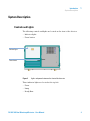
System Description
Controls and Lights
The following controls and lights are located on the front of the detector:
• Indicator lights
• Power button
Indicator lights
Power button
Figure 2
Lights and power button on the front of the detector
Three indicator lights are located at the top left:
• Power
• Lamp
• Ready/Run
325 UV/VIS Dual Wavelength Detector - User Manual
9
1
Introduction
System Description
At power up, the detector goes through an initialization sequence to check its
calibration and verify its overall operation. During this period, the LED’s on
the front of the detector change color to indicate its current status. The table
below defines each status:
Table 1
LED indicator lights
LED
Status
Color
Power
Power up
Initializing
Power on
Orange
Orange flashing
Green
Lamp
Initializing
Lamp on
Fault
Green flashing
Green
Red
Ready/Run
Not ready
Ready/Stopped
Method running
Off
Green
Orange
Press I (main power on) or O (main power off).
Optics Hardware
The main optics components are:
• UV and visible source lamp assembly
• Beam splitter
• Flowcell assembly
• Monochromator (containing collimators and grating)
• Photodiode detectors
The only user-serviceable optics components are the flowcell and lamp
assemblies. These assemblies are located behind the panel on the front right
side of the detector. To access the flowcell and lamp assemblies, see “Removing
the Front Panel” on page 39. All other optical components are pre-aligned and
sealed and must not be readjusted under any circumstance.
10
325 UV/VIS Dual Wavelength Detector - User Manual
1
Introduction
System Description
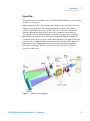
Optical Path
The optical path of the Agilent 325 UV/VIS Dual Wavelength Detector is shown
in Figure 3 on page 11.
Light coming from the source lamp is passed through a focusing lens before
hitting the beam splitter. The sample path then hits mirror N1 and the
reference path hits mirrors N2 and N3 . The two beams pass through an
entrance mask which shapes the beam to the geometry required before
entering the flowcell. Upon leaving the flowcell, they again pass through a
mask before entering the monochromator. This mask helps determine the
resolution of the detector optics. In the monochromator, the light is directed
onto the entry collimating mirror and then onto the grating. The dispersed
light hits the exit collimating mirror before leaving the monochromator
through the exit mask. From here the beams are focused onto the dual
photodiode detectors.
Figure 3
Optical ray trace diagram
325 UV/VIS Dual Wavelength Detector - User Manual
11
1
Introduction
System Description
Deuterium (UV) Lamp Assembly
The lamp assembly consists of the lamp bulb rigidly cemented into its
mounting bracket. The assembly is pre-aligned. Lamp replacement is easy to
perform, as no alignment procedures are required. See “Removing the Old
Lamp” on page 49 for instructions on how to replace the UV lamp.
Figure 4
12
Deuterium lamp optical path
325 UV/VIS Dual Wavelength Detector - User Manual
1
Introduction
System Description
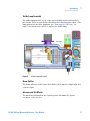
Visible Lamp Assembly
The visible lamp mounts on top of the optics module and is held in place by
two screws. These are in a fixed position therefore allowing replacement of the
lamp without the need for alignment. See “Removing the Old Lamp” on
page 51 for instructions on how to replace the visible lamp.
Figure 5
Visible lamp optical path
Beam Splitter
The beam splitter is a silica plate that divides the beam into sample light and
reference light.
Entrance and Exit Masks
The masks used throughout the optical system, determine the optical
resolution of the detector.
325 UV/VIS Dual Wavelength Detector - User Manual
13
1
Introduction
System Description
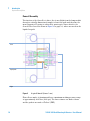
Flowcell Assembly
The function of the flowcell is to direct the focused light from the lamp module
through a critically dimensioned sample/solvent flow path and then into the
monochromator. Focusing is achieved by quartz optics lenses fitted to the
flowcell. The flowcell is shown in Figure 6 on page 14 , where arrows show the
liquid flow path.
Lens
Liquid path
Light
Figure 6
A typicall flowcell (9 mm x 1 mm)
Flowcells are made of titanium and have a maximum working pressure range
of approximately 68.95 bar (1000 psi). The lens retainers are made of brass
and the gaskets are made of Teflon® (FEP).
14
325 UV/VIS Dual Wavelength Detector - User Manual
1
Introduction
System Description
The flowcell and its attending hardware are designed for removal, installation
and replacement by the user. See “Installing a Flowcell” on page 43 for
instructions on how to replace the flowcell.
Whenever the type of flowcell is changed, you must perform a lamp calibration
(see “Calibrating the Lamps” on page 53).
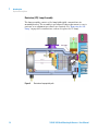
Monochromator
The monochromator is an enclosed unit that disperses a beam of light which
has been directed through the flowcell, and discriminates within 1 nm, to a
specifically selected wavelength. The monochromator is shown in Figure 7 on
page 16, indicated by the line.
The monochromator assembly contains the following components:
• An entrance mask (producing a well defined beam of polychromatic UV or
visible radiation)
• An entry collimating mirror
• A diffraction grating (dispersing incident radiation into a continuous
spectrum)
• A stepping motor (rotating the grating to obtain the desired wavelength of
exit radiation)
• An exit collimating mirror
• An exit mask (producing a very narrow bandwidth of light that is passed on
to the detectors)
325 UV/VIS Dual Wavelength Detector - User Manual
15
1
Introduction
System Description
Exit mask
Entrance mask
Figure 7
Table 2
Top view of the Monochromator (optical path)
Grating details
Grating size
70 mm x 45 mm
Blaze angle
8.5 ° (UV)
Balze wavelength
250 nm (UV-Vis)
Reciprocal dispersion
0.98 nm/mm (UV-Vis)
Lines per mm
1200 lines/mm (UV-Vis)
Photodiode Detectors
The detector is capable of operating in the 190 – 900 nm range. Dual silicon
photodiode detectors provide an output for measurement by the electronics
system.
16
325 UV/VIS Dual Wavelength Detector - User Manual
1
Introduction
System Description
Extended Range Operation
If you chose the 9 mm x 1 mm or 4 mm x 0.15 mm flowcell, extended range is
automatically turned on. Use the ratio indicated on the flowcell or use 8 for
the 9 mm x 1 mm and 28 for the 4 mm x 0.15 mm.
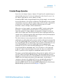
Normally in HPLC with a long pathlength flowcell, high sample concentrations
increase absorbance to the point of saturation. The light path becomes opaque
(transmittance near zero) and the signal output on the recorder or integrator
is truncated, or flat-topped. Any signal beyond this point is lost until
absorbance reduces enough to allow transmittance.
When there are large sample concentrations in HPLC, which result in high
absorbance, causing truncated peaks and loss of peak information, the
classical remedy is to reduce sample concentration or change to a flowcell
with a shorter light path. The flowcell with the shorter light path will be less
sensitive but its saturation point will be much higher, thereby allowing higher
sample concentration and Extended Range.
The ideal solution for increasing absorbance would be a flowcell with two
pathlengths, providing dual path operation, which would switch automatically
to the short pathlength when concentration became too high for operation on
the long pathlength. The useful dynamic range would be extended by the ratio
of the long pathlength to the short pathlength. If the maximum range
attainable on a detector with an 8 mm pathlength were 1.5 AU, then a 1 mm
flowcell would allow a maximum range of 12 AU relative to the 8 mm path
(8 mm x 1.5 mm). As the absorbance decreased, the detector would switch
back to operation on the long path for maximum signal-to-noise ratio.
The unique optional dual pathlength flowcells used in the Agilent 325 Detector
provide seamless automatic Extended Range. The dual pathlength flowcell
performs as two flowcells in one, allowing HPLC work well beyond the normal
+LIMIT value (the highest absorbance in normal range). As absorbance
continues to increase, the Agilent 325 Detector automatically switches to
operation on the short pathlength. The useful range is extended to the
extended +LIMIT, which is the normal +LIMIT multiplied by the flowcell ratio.
Extended Range operation is shown in Figure 8 on page 18.
325 UV/VIS Dual Wavelength Detector - User Manual
17
1
Introduction
System Description
Figure 8
Extended Range operation
The detector constantly samples both beams and records offset constants,
even in analytical operation. Because of this, the detector has in memory the
necessary constants to mathematically scale and seamlessly extend the long
path response with the short path response. During Extended Range
operation, the long pathlength is constantly sampled, and as absorbance
decreases there is a seamless switch back to dual beam operation in normal
range.
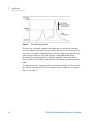
A comparison of two chromatograms, one from the Agilent 325 Detector and
the other from a typical UV detector using the same conditions, is shown in
Figure 9 on page 19.
18
325 UV/VIS Dual Wavelength Detector - User Manual
Introduction
System Description
Figure 9
1
Automatic Extended Range
325 UV/VIS Dual Wavelength Detector - User Manual
19
1
Introduction
Hydraulic Connections - Flowcells
Hydraulic Connections - Flowcells
Hydraulic connections are located at the front of the Agilent 325 Detector.
The only line installed by the user where dead volume and low holdup are
critical is the line from the column exit to the flowcell inlet port. This line
should be as short as possible.
The Agilent 325 Detector can be fitted with any one of four flowcells (ordered
separately). Each one has an inlet and outlet connection and quartz optics cell
window. Your chosen flowcell type is packed internally in the detector. The
four flowcell types are outlined in Table 3 on page 20.
Table 3
NOTE
20
Compatible flowcells
Flowcell type
Flowcell p/n
Pathlength1
Column ID
Flow rate
Maximum
pressure
Analytical
210181800
9 mm x 0 mm
2 – 8 mm
0.0001 –
10 mL/min
69 bar
(1000 psi)
Preparative2
210181900
9 mm x 1 mm
4 – 76 mm
1–
500 mL/min
69 bar
(1000 psi
Scale Up2
210224200
4 mm x
0.25 mm
4 – 76 mm
10 –
200 mL/min
69 bar
(1000 psi
Super Prep2
210182000
4 mm x
0.15 mm
8 – 152 mm
30 –
1200 mL/min
69 bar
(1000 psi
Micro-analytical
210182100
4 mm x 0 mm
1 – 4 mm
0 – 20 mL/min 69 bar
(1000 psi
1
A pathlength of a mm x b mm means that the sample light path has a pathlength of a mm, and the
reference light path has a pathlength of b mm. A reference light path of zero means there is no fluid
in the cell - air acts as the reference.
2
Extended range cell
It is important for the extended range cells to run at least at the minimum flow rate.
325 UV/VIS Dual Wavelength Detector - User Manual
1
Introduction
Detector Outlet Back Pressure Restrictor
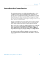
Detector Outlet Back Pressure Restrictor
The Back pressure restrictor (p/n 110743300) should be added to all flow
cells, unless a fraction collector is installed after the detector. The back
pressure restrictor assembly that was supplied with your detector should be
threaded into the outlet line from the flowcell. The back pressure restrictor
applies approximately 2.76 bar (40 psi) back pressure on the flowcell. This
prevents outgassing and bubbles from forming or being trapped in the flowcell,
which can cause an unstable baseline.
Note the arrow stamped on the restrictor body. This arrow must point away
from the flowcell outlet port, and toward the waste receiver. The threaded
plastic fittings should be finger tightened only enough to prevent leaks.
About 122 cm (48") of 1.6 mm (1/16") tubing is supplied at both the inlet and
outlet of the restrictor. The inlet tubing is provided with a 1.6 mm (1/16")
plastic tubing fitting for connecting to the flowcell outlet port. Either the
outlet tubing can be directed to the waste container, or the tubing removed,
and the restrictor itself dropped to the bottom of the waste bottle.
The restrictor pressure setting is not adjustable. If the restrictor fails or
becomes plugged, replace the existing cartridge with a new 2.76 bar (40 psi)
replacement.
325 UV/VIS Dual Wavelength Detector - User Manual
21
1
22
Introduction
Detector Outlet Back Pressure Restrictor
325 UV/VIS Dual Wavelength Detector - User Manual
325 UV/VIS Dual Wavelength Detector - User Manual
2
Site Requirements and Specifications
Site Requirements
24
Physical Specifications
26
Performance Specifications
27
This chapter provides information on environmental requirements, physical and
performance specifications.
Agilent Technologies
23
2
Site Requirements and Specifications
Site Requirements
Site Requirements
Power Considerations
The instrument power supply has wide ranging capability. It accepts any line
voltage in the range described in Physical Specifications.
WA R N I N G
Hazard of electrical shock or damage of your instrumentation
can result, if the devices are connected to a line voltage higher than specified.
➔ Connect your instrument to the specified line voltage only.
CAUTION
Inaccessible power plug.
In case of emergency it must be possible to disconnect the instrument from the power
line at any time.
➔ Make sure the power connector of the instrument can be easily reached and
unplugged.
➔ Provide sufficient space behind the power socket of the instrument to unplug the
cable.
Power Cords
Different power cords are offered as options with the module. The female end
of all power cords is identical. It plugs into the power-input socket at the rear.
The male end of each power cord is different and designed to match the wall
socket of a particular country or region.
24
325 UV/VIS Dual Wavelength Detector - User Manual
2
Site Requirements and Specifications
Site Requirements
WA R N I N G
Absence of ground connection or use of unspecified power cord
The absence of ground connection or the use of unspecified power cord can lead to
electric shock or short circuit.
➔ Never operate your instrumentation from a power outlet that has no ground
connection.
➔ Never use a power cord other than the Agilent Technologies power cord designed
for your region.
WA R N I N G
Use of unsupplied cables
Using cables not supplied by Agilent Technologies can lead to damage of the
electronic components or personal injury.
➔ Never use cables other than the ones supplied by Agilent Technologies to ensure
proper functionality and compliance with safety or EMC regulations.
WA R N I N G
Unintended use of supplied power cords
Using power cords for unintended purposes can lead to personal injury or damage of
electronic equipment.
➔ Never use the power cords that Agilent Technologies supplies with this instrument
for any other equipment.
Condensation
CAUTION
Condensation within the module
Condensation will damage the system electronics.
➔ Do not store, ship or use your module under conditions where temperature
fluctuations could cause condensation within the module.
➔ If your module was shipped in cold weather, leave it in its box and allow it to warm
slowly to room temperature to avoid condensation.
325 UV/VIS Dual Wavelength Detector - User Manual
25
2
Site Requirements and Specifications
Physical Specifications
Physical Specifications
Table 4
26
Specifications Agilent 325 Detector
Type
Specification
Rated Voltage
100 – 240 VAC ±10 %, 50 /60 Hz ±1 Hz
single phase
Power consumption
130 VA
Ambient operating
temperature
10 – 35 °C (50 – 95 °F)
Ambient non-operating
temperature
-20 – 65 °C (-4 – 149 °F)
Ambient laboratory
temperature
20 – 25 °C (68 – 77 F) ± 2 °C (35.6 F)
Humidity
5 – 95 %
Operating altitude
2000 m (6562 feet)
Weight
15.5 kg (34.2 lbs)
Weight (Packed)
21 kg (46.3 lbs)
Size
(height x width x depth)
212 x 296 x 475 mm
(8.3 x 11.7 x 18.7 in)
Packaged Size (height x
width x depth)
385 x 460 x 775 mm
(15.2 x 18.1 x 30.5 in)
Safety standards:
IEC, CSA, UL
Overvoltage Category II, Pollution
Degree 2
Comments
Maximum
For indoor use only.
325 UV/VIS Dual Wavelength Detector - User Manual
Site Requirements and Specifications
Performance Specifications
2
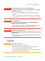
Performance Specifications
Table 5
Performance specifications Agilent 325 Detector
Type
Specification
Diagnostics
Built-in self-test and diagnostics
Time programming
•
•
•
•
•
•
•
•
Wavelength
UV (Deuterium) lamp and visible (quartz halogen) lamp, 190 –
900 nm
Flowcell
Optional
• 9 x 0 mm
• 9 x 1 mm
• 4 x 0 mm
• 4 x 0.15 mm
• 4 x 0.25 mm
Pressure
69 bar (1000 psi) maximum on flowcells
Response time
0.05 s, 0.5 s, 1.0 s, 2.0 s
Spectral bandwidth
5 nm
Recorder output
1 V FS
Data System output
1 V FS
Peak sensing
The following events will activate the Peak Sense relay and
generate event marks on the recorder chart:
• Peak Start
• Peak End
• Valley
• Time Slice
• Pulse
Time programmable wavelength
Recorder attenuation
Auto-zero
Response time (programmable at time = zero only)
Peaksense
Timeslice
Pulse and external event relays
Method storage
325 UV/VIS Dual Wavelength Detector - User Manual
27
2
Site Requirements and Specifications
Performance Specifications
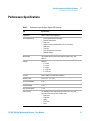
Table 5
Performance specifications Agilent 325 Detector
Type
Specification
External communication
To other instruments using synchronization cables.
Mains inlet coupler
3/2 A 120/150 VAC 50 – 60 Hz IEC type
Mains power cord
•
•
•
Australia: 10 A250 VAC complies with AS3112
USA: 10 A125 VAC complies with NEMA 5-15P
Europe: 6 A250 VACcomplies with CEE7 sheet vii or
NFC61.303VA
Rear connectors
•
J1 Comm: Ethernet TCP/IP RJ-45 type connector (system
connection)
J14 Analog out: female 9-pin D-range connector
J4 Relay out: female 15-pin D-range connector
P9 Sync signals: male 15-pin D-range connector
J10 Sync signals: female 9-pin D-range connector
•
•
•
•
Contact closure outputs
•
•
•
4 time progammable external event relays
1 peak sense relay
3 synchronization signals (READY OUT, START OUT, FALUT
OUT)
Contact closure inputs
•
•
3 synchronization signals (READY IN, START IN, FAULT IN)
LAMP OFF and AUTO-ZERO
Bus communication
The Agilent 325 UV/VIS Dual Wavelength Detector will
communicate with OpenLAB by means of Ethernet.
Fuses
T3.15AH250V (5 x 20 mm) IEC 127 Sheet 51 (5 x 20 mm)
1
28
Fuse information on the rear of the instrument is the most up-to-date.
325 UV/VIS Dual Wavelength Detector - User Manual
325 UV/VIS Dual Wavelength Detector - User Manual
3
Installation
Installation
30
This chapter gives information about the installation of your instrument.
Agilent Technologies
29
3
Installation
Installation
Installation
For details on installation of the module, refer to Agilent 218 Purification
System – Setup and Installation Guide (p/n G9300-90300).
30
325 UV/VIS Dual Wavelength Detector - User Manual
325 UV/VIS Dual Wavelength Detector - User Manual
4
Using the Detector
General
32
This chapter explains the operational parameters of the instrument.
Agilent Technologies
31
4
Using the Detector
General
General
For information about using the Agilent 325 UV/VIS Dual Wavelength Detector
refer to the help of the Control Software.
32
325 UV/VIS Dual Wavelength Detector - User Manual
325 UV/VIS Dual Wavelength Detector - User Manual
5
Troubleshooting and Diagnostics
Excessive Noise and/or Drift
34
This chapter gives an overview about the troubleshooting and diagnostic
features.
Agilent Technologies
33
5
Troubleshooting and Diagnostics
Excessive Noise and/or Drift
Excessive Noise and/or Drift
Excessive noise and/or drift has several sources:
• A contaminated or leaking flowcell
• A worn out lamp
• A temperature fluctuation of the location where the detector is installed
due to air vents or sunshine
NOTE
If the flowcell is the problem, clean it (see “Cleaning the Flowcell” on page 46 for more
information). If the cleaning procedure does not rectify the problem, it will be necessary to
replace the flowcell assembly (see “Installing a Flowcell” on page 43 for more information).
If one of the lamps is the problem source, it must be replaced with a new lamp.
1 If cleaning or replacing the flowcell and/or replacing the lamps does not fix
the problem, call your Agilent service representative.
34
325 UV/VIS Dual Wavelength Detector - User Manual
325 UV/VIS Dual Wavelength Detector - User Manual
6
Maintenance
General
36
Warnings and Cautions
37
Removing the Front Panel
39
Installing and Removing the Door
Installing the Door
40
41
Installing a Flowcell
43
Maintaining and Cleaning the Flowcell 46
Cleaning the Flowcell 46
Cleaning the Exterior of the Flowcell 48
Maintaining of the Flowcell 48
Replacing the Deuterium (UV) Lamp 49
Removing the Old Lamp 49
Installing the New UV Lamp 50
Replacing the Visible Lamp 51
Removing the Old Lamp 51
Installing the New Visible Lamp
Calibrating the Lamps
52
53
Cleaning the Instrument
55
This chapter describes the maintenance of the instrument.
Agilent Technologies
35
6
Maintenance
General
General
The Agilent 325 UV/VIS Dual Wavelength Detector requires three maintenance
procedures to be performed periodically:
• Changing and cleaning the flowcell
• Replacing the lamp(s)
• Calibrating the lamps
Flowcell removal and replacement will be necessary if a flowcell of different
pathlength is desired, or if cleaning procedures do not satisfactorily clean the
cell.
Lamp replacement is required when the lamp output deteriorates to the level
that it affects the reliability of analytical results.
Whenever a lamp is changed or the flowcell type is changed, perform a lamp
calibration. Also perform a periodic calibration once per month.
This chapter also covers cleaning of the instrument.
36
325 UV/VIS Dual Wavelength Detector - User Manual
6
Maintenance
Warnings and Cautions
Warnings and Cautions
WA R N I N G
Toxic, flammable and hazardous solvents, samples and reagents
The handling of solvents, samples and reagents can hold health and safety risks.
➔ When working with these substances observe appropriate safety procedures (for
example by wearing goggles, safety gloves and protective clothing) as described in
the material handling and safety data sheet supplied by the vendor, and follow good
laboratory practice.
➔ The volume of substances should be reduced to the minimum required for the
analysis.
➔ Do not operate the instrument in an explosive atmosphere.
WA R N I N G
Eye damage by detector light
Eye damage may result from directly viewing the UV-light produced by the lamp of
the optical system used in this product.
➔ Always turn the lamp of the optical system off before removing it.
WA R N I N G
Electrical shock
Risk of stroke and other personal injury.
➔ Turn the main power switch to OFF and disconnect the power cord to the detector
before starting the lamp replacement procedure.
325 UV/VIS Dual Wavelength Detector - User Manual
37
6
Maintenance
Warnings and Cautions
WA R N I N G
Injury by touching hot lamp housing
If the detector has been in use, the lamp housing may be hot.
➔ Turn off the lamp.
➔ Let the lamp housing cool before removing the lamp.
CAUTION
Lamp failure
Oil or other material on the lamp glass envelope can cause the lamp to explode.
➔ Never touch the glass on the lamp with bare hands.
➔ Always wear gloves when replacing the lamp.
38
325 UV/VIS Dual Wavelength Detector - User Manual
6
Maintenance
Removing the Front Panel
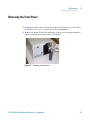
Removing the Front Panel
1 If installed, remove the door from the Agilent 325 Detector (see “Installing
and Removing the Door” on page 40 for more information).
2 Remove the panel on the front right side of the detector by unscrewing the
captive screw in the top left corner of the panel.
Figure 10
Removing the front panel
325 UV/VIS Dual Wavelength Detector - User Manual
39
6
Maintenance
Installing and Removing the Door
Installing and Removing the Door
1 Gently push down on the door and slide the lower hinge pin out of the lower
hinge.
2 Lift and slide out the top of the door.
40
325 UV/VIS Dual Wavelength Detector - User Manual
6
Maintenance
Installing the Door
Installing the Door
The module door may be attached to the front of the Agilent 325 Detector to
cover the tubing connections to the flowcell.
NOTE
If the Agilent 325 Detector is the top module in the stack, the door cap should be installed
before installing the door on the module.
Installing the Door Cap
If the Agilent 325 Detector is not at the top of the stack, do not install the
cap and proceed to the instructions describing door installation.
1 Stand the door upside down on a flat surface (i.e., with the two ribs
towards the bottom).
Ribs
Magnetic latch
Door cap
Figure 11
Installing the door cap
2 Take the cap and remove the protective paper exposing the adhesive that
will attach the cap to the door.
325 UV/VIS Dual Wavelength Detector - User Manual
41
6
Maintenance
Installing the Door
3 Insert the cap into the door and press the adhesive onto the inside of the
door lip. Be sure to keep the door edges and cap edges flush.
Installing the Door
1 Insert the top hinge pin into the top hinge.
2 Gently press down on the top of the door and slide the lower hinge pin into
the lower hinge. The door should now pivot on the pins and close. The
magnetic door latch should stick to the instrument.
Figure 12
42
Installing the Agilent 325 Detector door
325 UV/VIS Dual Wavelength Detector - User Manual
Maintenance
Installing a Flowcell
6
Installing a Flowcell
The Agilent 325 UV/VIS Dual Wavelength Detector is not shipped with a
flowcell installed. You will need to install the flowcell that you purchased with
the detector. Each flowcell comes with a set of recommended nuts and ferrules
that may be fitted to tubing.
1/16" tubing is used on all flowcells. However for the 4 mm x 0.15 mm super
prep. flowcell it is recommended to use 1/8" tubing at higher flow rates. In this
case you can add the Adaptor 1/8" - 1/16" (p/n 1610126800). This will require
the 1/8" tubing and the 1/8" flowcell fittings.
Tubing connections are PEEK™ type, except for the Super Prep flowcell which
uses Tefzel® tubing 0.125 mm x 0.062 mm.
Parts required
#
p/n
Description
1
210181800
Flowcell 9 mm x 0 mm, inert (analytical)
OR
1
210181900
Flowcell 9 mm x 1 mm, inert (prep.)
OR
1
210224200
Flowcell 4 mm x 0.25 mm, inert (scale up)
1
210182100
Flowcell 4 mm x 0 mm, inert (micro-analytical)
1
9910128300
Flow cell replacement fittings
1
210182000
Flowcell 4 mm x 0.15 mm,inert (super prep.)
1
1610126900
Fitting 1/8" tube nut flat bottom
1
1610126400
Fitting 1/8" tube ferrule, Pack of 10
1
1610126800
Adaptor 1/8" - 1/16"
OR
1
325 UV/VIS Dual Wavelength Detector - User Manual
43
6
Maintenance
Installing a Flowcell
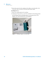
1 Fit the nuts and ferrules on the PEEK™ tubes.
2 Screw the two tubes into the inlet and outlet connection
of the flowcell. Each flowcell has an inlet and outlet
connection.
;ZggjaZ
I]jbWhXgZl
Cji
DjiaZiXdccZXi^dc
E::@ijWZ
>caZiXdccZXi^dc
IjW^c\
NOTE
The position of the inlet and outlet connections varies
for different flowcells.
44
3 Remove the front panel (see “Removing the Front
Panel” on page 39 for more information).
325 UV/VIS Dual Wavelength Detector - User Manual
Maintenance
Installing a Flowcell
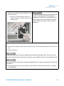
4 Carefully position the flowcell so that the two
thumbscrews are positioned in the threaded holes in the
flowcell compartment.
6
NOTE
It is critical to the performance of the detector that the
flowcell is inserted correctly. The internal optical
a Push at the center of the flowcell to ensure it is
components of the flowcell are an integral part of the
positioned squarely in its housing and that it is not
detector’s optical system. If the flowcell is not fitted
tilted in any way.
correctly, it will have an adverse effect on detector
performance.
Next Steps:
5 Secure the flowcell by tightening the thumbscrews with your fingers. Alternate tightening the thumbscrews until they are
snug.
6 Replace the front panel.
NOTE
For optimum performance, the detector should be operated with the front panel in place. This is because the
foam on the inside of the panel stops breezes, which may cause instability and noise, from reaching the flowcell.
NOTE
The flowcell should be removed with the connecting tubing fitted. These must be removed outside the detector
compartment.
7 Perform a lamp calibration (see chapter maintenance in Agilent 325 UV/VIS Dual Wavelength Detector - User Manual
(p/n G9309-90000)).
325 UV/VIS Dual Wavelength Detector - User Manual
45
6
Maintenance
Maintaining and Cleaning the Flowcell
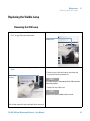
Maintaining and Cleaning the Flowcell
Cleaning the Flowcell
When
The frequency of need for cell cleaning depends to a great extent upon the cleanliness maintained
during routine operation. In severe cases of contamination, for instance if there is precipitate in the
cell, the cell must be replaced.
Tools required
Description
HPLC grade water
Phosphoric acid, 85 %
Methanol
OR
Acetonitrile
Parts required
Description
Stainless steel tubing 1.6 mm (1/16") o.d.
CAUTION
Contamination of exposed fittings
Contaminated flowcells can lead to noise and drift problems.
➔ Seal or cap tubings when not connected.
➔ Never apply thread lubricants to compression fittings.
CAUTION
Dismantled flowcell
The flowcell can be damaged.
➔ Do not dismantle the flowcell.
1 Remove all reservoirs containing organic solvent from the system.
2 Replace the column with a clean length of 1.6 mm (1/16") o.d. stainless steel
tubing.
3 Fill all of the reservoirs with HPLC grade water and flush the system
thoroughly to remove any trace of organic solvents.
46
325 UV/VIS Dual Wavelength Detector - User Manual
6
Maintenance
Maintaining and Cleaning the Flowcell
4 After the system has been rinsed with water, pump 50 mL of 25 %
phosphoric acid at 1 – 2 mL/min through the flowcell.
NOTE
The acid is prepared by diluting one part of concentrated phosphoric acid (85 %) with three
parts of HPLC grade water.
NOTE
Do not allow the acid to remain in the cell for more than one hour.
5 Rinse the flowcell by pumping 100 – 200 mL of HPLC grade water through
the system.
NOTE
Dispose of the acid in accordance with approved waste disposal procedures.
6 Finally rinse the flowcell with acetonitrile or methanol.
325 UV/VIS Dual Wavelength Detector - User Manual
47
6
Maintenance
Maintaining and Cleaning the Flowcell
Cleaning the Exterior of the Flowcell
Tools required
Description
OR
Compressed nitrogen
Compressed air
1 Remove the flowcell from the detector (see “Installing a Flowcell” on
page 43 for more information) and carefully blow any dust or
contamination from the external windows with a dry, clean soure of
compressed air or nitrogen.
2 Replace the flowcell, ensuring that the sample and reference beam windows
are not obstructed (see “Installing a Flowcell” on page 43 for more
information).
Maintaining of the Flowcell
The high sensitivity of the detector and the low volume of the flowcell make it
imperative that a high standard of solvent purity and general system
cleanliness be maintained. A contaminated flowcell can lead to noise and drift
problems that are often mistakenly attributed to other areas of the system.
To avoid possible degradation in performance, remember the following:
• Store the flowcells sealed in plastic bags if they are not in the detector.
• Set the flowcell with the faceplate upward if they are removed from the
detector.
• Avoid touching the inside of the flowcell recess.
• Cover the flowcell opening with a piece of card, or always place a flowcell in
the flowcell opening.
48
325 UV/VIS Dual Wavelength Detector - User Manual
6
Maintenance
Replacing the Deuterium (UV) Lamp
Replacing the Deuterium (UV) Lamp
Removing the Old Lamp
1 Remove the front panel (see “Removing the Front
Panel” on page 39 for more information).
2 Squeeze the small latch on the 3-way connector and pull
the connector out.
("lVn
8dccZXidg
3 Undo the first captive screw.
NOTE
Retain screw for re-installation.
8Vei^kZhXgZl
325 UV/VIS Dual Wavelength Detector - User Manual
49
6
Maintenance
Replacing the Deuterium (UV) Lamp
4 Undo the second captive screw.
5 Lift up the silver saftey interlock latch on the right and
remove the lamp, holding onto the thumbscrews.
H^akZghV[Zin
adX`
Next Steps:
6 Remove the lamp assembly and discard it.
NOTE
No part of the old assembly can be re-used, except for the captive screws.
Installing the New UV Lamp
Your new replacement lamp is delivered to you pre-tested and aligned in a
mounting bracket. It is designed for direct replacement and requires no
alignment procedures after it has been installed.
1 Lift the silver interlock latch, and carefully insert the lamp into the lamp
housing.
2 Screw in the two thumbscrews.
3 Connect the 3-way connector into the socket.
4 Re-engage the saftey interlock latch by sliding it down.
5 Replace the front panel and screw in the captive screw in the top left corner
of the panel.
6 Re-install the door (see “Installing the Door” on page 41 for more
information).
7 Perform a lamp calibration (see “Calibrating the Lamps” on page 53 for
more information).
50
325 UV/VIS Dual Wavelength Detector - User Manual
Maintenance
Replacing the Visible Lamp
6
Replacing the Visible Lamp
Removing the Old Lamp
1 Remove the front panel (see “Removing the Front
2 Undo the visible lamp holding screw.
Panel” on page 39 for more information).
Holding screw
3 Remove the visible lamp housing by holding it via the
Next Steps:
screw.
4 Gently grip the visible lamp between your thumb and
K^h^WaZaVbe
]djh^c\
finger and pull the lamp towards you.
NOTE
The visible lamp has two prongs which slide into two
connecting sockets.
5 Remove the lamp and discard.
NOTE
No part of the old assembly can be re-used.
This will then expose the lamp, which will still be connected.
325 UV/VIS Dual Wavelength Detector - User Manual
51
6
Maintenance
Replacing the Visible Lamp
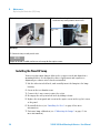
Installing the New Visible Lamp
Your new replacement lamp is delivered to you pre-tested and requires no
alignment procedures after it has been installed.
1 Gently grip the lamp between your thumb and forefinger.
2 Insert the two small prongs of the lamp into the two holes in the lamp
compartment and gently push the lamp in.
3 Attach the lamp housing by inserting the screw into the hole and tightening
the thumbscrew with your fingers.
4 Replace the front panel and screw in the captive screw in the top left corner
of the panel.
5 Re-install the door (see “Installing the Door” on page 41 for more
information).
6 Perform a lamp calibration (see “Calibrating the Lamps” on page 53 for
more information).
52
325 UV/VIS Dual Wavelength Detector - User Manual
6
Maintenance
Calibrating the Lamps
Calibrating the Lamps
Lamp calibration minimizes noise by allowing the maximum gain settings to be
used. It also improves linearity by re-balancing the 0 %T correction tables as
lamps age.
If a calibration is performed with a bubble in the cell, or no cell is fitted, the
gain settings will be too high to cope with a cell present and full of water.
Readings will be overrange, and will not respond to changes in absorbance.
Noise will either be very high, or zero. If the gains are set just too high,
chromatograms may show peaks that are cut off at the bottom.
Parts required
OR
OR
Preparations
#
p/n
Description
1
210181800
Flowcell 9 mm x 0 mm, inert (analytical)
1
210181900
Flowcell 9 mm x 1 mm, inert (prep.)
1
210224200
Flowcell 4 mm x 0.25 mm, inert (scale up)
1
210182000
Flowcell 4 mm x 0.15 mm,inert (super prep.)
1
210182100
Flowcell 4 mm x 0 mm, inert (micro-analytical)
1
110743300
Back pressure restrictor
Unless a fraction collector is installed after the detector, the Back pressure restrictor (p/n
110743300) assembly that was supplied with your detector should always be threaded into the
outlet line from the flowcell.
The back pressure restrictor provides approximately 2.76 bar (40 psi) back pressure on the flowcell.
This prevents outgassing and bubbles from forming or being trapped in the flowcell, which can
cause an unstable baseline. See “Detector Outlet Back Pressure Restrictor” on page 21 for more
information about the Back pressure restrictor (p/n 110743300) .
•
•
•
Be sure a flow cell is fitted in the detector.
To keep the flowcell clear of bubbles, pump clean water with 0.2 – 1 mL/min through the cell.
After turning on the lamp, wait at least half an hour to get the best linearity correction before
starting the calibration.
325 UV/VIS Dual Wavelength Detector - User Manual
53
6
Maintenance
Calibrating the Lamps
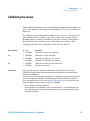
1 In the Toolbar, tap the Calibration icon.
2 Tap the Lamp Calib button. If the system is in the Not Ready state, a message
will appear stating that the system must be in the Ready state.
54
NOTE
The lamp calibration will now be performed and the process may takes several minutes.
NOTE
A lamp calibration can also be performed in OpenLAB.
325 UV/VIS Dual Wavelength Detector - User Manual
Maintenance
Cleaning the Instrument
6
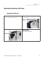
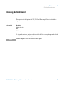
Cleaning the Instrument
The exterior of the Agilent 325 UV/VIS Dual Wavelength Detector should be
kept clean.
Tools required
Description
Soft, lint free cloth
Water
Mild detergent
1 Clean the exterior surfaces with a soft cloth. If necessary, dampen the cloth
with water or a mild detergent.
NOTE
Do not use organic solvents or abrasive cleaning agents.
325 UV/VIS Dual Wavelength Detector - User Manual
55
6
56
Maintenance
Cleaning the Instrument
325 UV/VIS Dual Wavelength Detector - User Manual
325 UV/VIS Dual Wavelength Detector - User Manual
7
Parts
Parts List
58
This chapter provides information on parts for the instrument.
Agilent Technologies
57
7
Parts
Parts List
Parts List
58
p/n
Description
G9309A
Agilent 325 UV-VIS Dual Wavelength Detector
110728800
Agilent 325 detector door
910206600
Door cap
110743300
Back pressure restrictor
110715400
Assy D2 lamp (pre-aligned) 325
210186590
Assy PWB sync. interface 325
210187590
Assy PWB relay interface 325
210181800
Flowcell 9 mm x 0 mm, inert (analytical)
210181900
Flowcell 9 mm x 1 mm, inert (prep.)
210224200
Flowcell 4 mm x 0.25 mm, inert (scale up)
210182000
Flowcell 4 mm x 0.15 mm,inert (super prep.)
210182100
Flowcell 4 mm x 0 mm, inert (micro-analytical)
1910010700
Fuse 3.15 A
5610136500
Lamp miniature quartz halogen 325
9910128300
Flow cell replacement fittings
1610126800
Adaptor 1/8" - 1/16"
1610126900
Fitting 1/8" tube nut flat bottom
1610126400
Fitting 1/8" tube ferrule, Pack of 10
325 UV/VIS Dual Wavelength Detector - User Manual
325 UV/VIS Dual Wavelength Detector - User Manual
8
Cables
Cable Overview
60
Cable Connections
Analog Output
Relay Output
61
62
63
Desktop PC Communications
Synchronization Signals
66
67
This chapter provides information on cables used with the instrument.
Agilent Technologies
59
8
Cables
Cable Overview
Cable Overview
Necessary cables
p/n
Description
392612901
Ethernet cable (for use in a network)
5023-0203
Ethernet cable (cross-over, for standalone use)
392607969
Inject marker cable
392607975
Next injection cable
393546291
Serial communication ribbon
393597601
Converter RS232 to RS422
7910046300
Serial cable
Optional cables
60
p/n
Description
110743800
Relay interface cable (for relay interface board, one relay contact per cable)
110744200
Analog signal cable
325 UV/VIS Dual Wavelength Detector - User Manual
8
Cables
Cable Connections
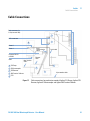
Cable Connections
Back connectors for
218 (to internal CIM)
7725i
1
9-Pin connectors
1
5
Comm 2
Serial
communication
ribbon
Comm 1
Converter RS 232
to RS422
Serial cable
Ethernet
cable
GPIB
Next injection
cable
4
1 218 Pump
2
2 410 Autosampler
3 325 Detector
4 440 Fraction Collector
3
Inject marker cable
5 CPU
Figure 13
Cable connections for workstation control of Agilent 218 Pumps, Agilent 325
Detector, Agilent 410 Autosampler and Agilent 440 Fraction Collector
325 UV/VIS Dual Wavelength Detector - User Manual
61
8
Cables
Analog Output
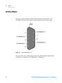
Analog Output
For analog output signals, install the optional Analog signal cable (p/n
110744200) into the J14 receptacle. Pin designations are shown below.
Figure 14
Pin designation for J14
The open ends of the analog output cable have labels with the signal names
(Channel A +, Channel A - and Channel B +, Channel B -).
62
325 UV/VIS Dual Wavelength Detector - User Manual
8
Cables
Relay Output
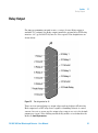
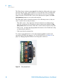
Relay Output
For time programming external events, a contact closure Relay output is
available. To configure the Relay output, install the optional Assy PWB relay
interface 325 (p/n 210187590) into the J4 receptacle. Pin designations are
shown below.
Figure 15
Pin designation for J4
There are four general purpose output relays and one dedicated Peak relay.
Each output uses a DIP relay that is capable of handling 500 mA of contact
current. At reset or power up, the output relay contacts are set to the default
parameters (open). After loading a method they will be set as defined in the
method’s time=0 parameters.
325 UV/VIS Dual Wavelength Detector - User Manual
63
8
Cables
Relay Output
The Peak relay is software programmable for duration, delay and active sense.
At power up, the relay contact will be set to the inactive state (as defined by
the value of the active sense parameter stored in the detector). Upon being
triggered, relay activation will occur for the time interval equal to the Peak
Sense duration parameter as stored in the method.
The Peak relay can be activated from any of the following sources (only one
source can be active at any one time):
• Time Slice event – Once time slice has been turned on, it will provide a
periodic activation of the Peak Sense relay at an interval defined in Time
Slice period within the method. Time Slice can be turned on and off by time.
• Pulse event – A single timed programmed activation of the Peak Sense relay
as defined in the method.
• Peak sense has been turned on.
To connect open-ended wires to the relay signals available at J4, use the
optional Assy PWB relay interface 325 (p/n 210187590) (see Figure 16 on
page 64). Simply plug this PWB into the rear panel connector.
Figure 16
64
Relay output board
325 UV/VIS Dual Wavelength Detector - User Manual
8
Cables
Relay Output
The Relay interface cable (for relay interface board, one relay contact per
cable) (p/n 110743800) is used to attach to the 3 pin connectors at the relay
output board.
With the 3 pin connectors, the contact closure is between pins 1 and 2 of the
plugs. Pin 3 is connected to ground. The relay interface cable has three
open-ended wires. The relay contact is connected between the clear and the
black wire. The green wire is connected to ground.
325 UV/VIS Dual Wavelength Detector - User Manual
65
8
Cables
Desktop PC Communications
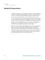
Desktop PC Communications
Communication between the detector and a desktop PC occurs by an Ethernet
connection. Communication by an Ethernet connection is required to control
the detector remotely by OpenLAB. When the Workstation provides HPLC
system control, the synchronization cables from P9 and J10 are not used.
To create an Ethernet connection, insert an RJ45 cable included in the ship kit
into the J1 receptacle and into the PC. The Ethernet cable that comes with the
detector is a cross-over cable, which is appropriate for connecting the detector
directly to a PC. Connecting the detector to a network or a hub will usually
require a patch cable. A Ethernet cable (for use in a network) (p/n
392612901) can be purchased from Agilent or either locally.
Most PCs come pre-configured with an Ethernet connection, which is usually
built into the motherboard, or with an Ethernet network card installed.
However, if you have a PC that has no network interface, you will need to
install and configure a Network Interface Card (PCI bus). The PC must have a
spare PCI slot for the installation of this device. You are also responsible for
setting up and maintaining any LAN configuration where a detector may be
used. All network issues are to be dealt with by the user.
66
325 UV/VIS Dual Wavelength Detector - User Manual
8
Cables
Synchronization Signals
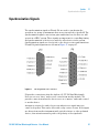
Synchronization Signals
The synchronization signals at P9 and J10 are used to synchronize the
operation of a group of instruments that are not interfaced to OpenLAB. The
synchronization signals come in four pairs and define how the detector will
operate in a HPLC system. These signals are important for controlling timing
and synchronization of the detector with the other devices in the system.
Synchronization signals are closely tied to the detector states and transitions.
P9 and J10 pin designations are shown in Figure 17 on page 67.
Figure 17
Pin designations for J10 and P9
P9 provides connections when the Agilent 325 UV/VIS Dual Wavelength
Detector acts as a “slave” and receives control from another module. J10
provides connections when the detector acts as a “master” and sends control
to another device.
An input is activated or said to be present when its two signal wires are
connected together. This can be done with a relay contact closure. If the inputs
are driven from another instrument with optical isolators or other polarized
devices, then attention must be paid to the polarity of the signal wire
325 UV/VIS Dual Wavelength Detector - User Manual
67
8
Cables
Synchronization Signals
connections. The positive (+) output signal must be connected to the positive
(+) input signal and the negative (-) output to the negative (-) input.
The color coding and physical design of the cable connectors ensure that
correct signals and polarity are matched.
The outputs are optical isolators and simulate a relay contact closure when
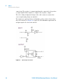
they are activated (see Figure 18 on page 68). The minimum requirement for
an input signal to be detected is 200 ms.
Figure 18
68
Input/output schematics
325 UV/VIS Dual Wavelength Detector - User Manual
8
Cables
Synchronization Signals
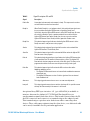
Table 6
Signal Description J10 and P9
Signal
Description
Enable Out
A non-polarized constantly active output (a short). This output can be used to
activate Enable In on the next instrument.
Ready In
When Enable Ready In is set (software switch), this polarized input signal must
be present before the Agilent 325 Detector can go to the Ready state.
Specifically, when the Agilent 325 Detector is in the NOT Ready Lamp On state,
on receiving a Ready In signal, a monitor period will occur after which the
Agilent 325 Detector goes to the Ready state. It must stay active until the
Agilent 325 Detector starts. Ready In will be ignored in all other states.
Ready Out
This polarized output signal indicates that the Agilent 325 Detector is in the
Ready state and is ready to start a time program.
Start In
This polarized edge triggered input signal will start the active method if the
Agilent 325 Detector is in the Ready state.
Start Out
This polarized output signal will be activated for 600 ms when the Agilent 325
Detector starts a time program.
Fault In
This polarized edge triggered input signal informs the Agilent 325 Detector that
a fault condition exists in another instrument in the system. The Agilent 325
Detector halts the time program and sends a Fault Out signal. The lamp can be
programmed to either remain on or turn off upon receiving a fault signal.
Fault Out
This polarized output signal will activate for 600 ms when either of the
following conditions occurs:
• The Agilent 325 Detector discovers an internal fault condition that warrants
aborting the run.
• The Agilent 325 Detector receives a Fault In signal and it has no internal
fault condition itself.
Auto-zero
This edge-triggered contact closure causes an auto-zero adjustment.
Lamp off
This edge-triggered contact closure switches the lamp off. It is possible to turn
the lamp back on manually if the contact is still closed.
An optional Assy PWB sync. interface 325 (p/n 210186590) is available to
interface between the Agilent 325 UV/VIS Dual Wavelength Detector
synchronization signals and other devices. This board is inserted into the P9
and J10 connectors and connects to a terminal strip on the adapter board.
This terminal strip accepts bare wire leads from cables connecting other
devices. These cables may originate from the other device, or a dedicated cable
can be used, if available for the particular application.
325 UV/VIS Dual Wavelength Detector - User Manual
69
8
Cables
Synchronization Signals
Figure 19
70
The I/O adapter board
325 UV/VIS Dual Wavelength Detector - User Manual
325 UV/VIS Dual Wavelength Detector - User Manual
9
Appendix
General Safety Information
72
The Waste Electrical and Electronic Equipment Directive
Batteries Information
Radio Interference
CE Compliance
78
79
80
81
Electromagnetic Compatibility
Agilent Technologies on Internet
82
83
This chapter provides addition information on safety, legal and web.
Agilent Technologies
71
9
Appendix
General Safety Information
General Safety Information
General Safety Information
The following general safety precautions must be observed during all phases of
operation, service, and repair of this instrument. Failure to comply with these
precautions or with specific warnings elsewhere in this manual violates safety
standards of design, manufacture, and intended use of the instrument. Agilent
Technologies assumes no liability for the customer’s failure to comply with
these requirements.
WA R N I N G
Ensure the proper usage of the equipment.
The protection provided by the equipment may be impaired.
➔ The operator of this instrument is advised to use the equipment in a manner as
specified in this manual.
72
325 UV/VIS Dual Wavelength Detector - User Manual
Appendix
General Safety Information
9
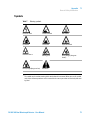
Symbols
Table 7
Warning symbols
Electrical shock
Chemical hazard
Hot surface
Eye hazard
Fire hazard
Explosion hazard
Moving parts
Heavy weight (danger to
hands)
Radiation Source
Heavy weight (danger to feet)
1
Attention1
The symbol may be used on warning labels attached to the instrument. When you see this symbol,
refer to the relevant operation or service manual for the correct procedure referred to by that warning label.
325 UV/VIS Dual Wavelength Detector - User Manual
73
9
Appendix
General Safety Information
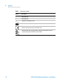
Table 8
Information symbols
Symbol
Description
I
Mains power on
0
Mains power off
Single phase alternating current
Fuse
When attached to the rear of the instrument, indicates that the product complies
with the requirements of one or more EU directives.
When attached to the rear of the product, indicates that the product has been
certified (evaluated) to CSA 61010.1 and UL 61010-1.
74
325 UV/VIS Dual Wavelength Detector - User Manual
Appendix
General Safety Information
9
Solvent Hazards
WA R N I N G
Explosion, fire, asphyxiation
This instrument is not explosion-proof.
Certain solvents may cause weakening and leaks of tubings or fitthings with
possible bursting.
Even small leaks in solvent supply systems can be dangerous.
➔ Only use solvents compatible with the HPLC system tubings and fittings.
➔ Employ static measuring and static discharge devices to safeguard against the
buildup of static electricity.
➔ In unattended operation, do not use organic solvents having an ignition point below
70 °C.
➔ Do not bring a heat or flame source near the instrument.
➔ The area in which solvents are stored and the area surrounding the instrument must
be adequately ventilated to prevent accumulations of gas.
➔ Always check the condition of the instrument (leakage of solvent or waste solution,
leakage of solvent inside the instrument). If an abnormality is found, stop operation
immediately.
➔ When using flammable chemicals, be careful about possible ignition due to static
electricity. To prevent the build-up of static electricity, use a conductive container
for waste.
➔ Use only approved regulator and hose connectors (refer to the supplier’s
instructions).
➔ Keep solvents cool and properly labeled. Ensure that you have the correct solvent
before connecting it to the instrument.
325 UV/VIS Dual Wavelength Detector - User Manual
75
9
Appendix
General Safety Information
WA R N I N G
Inflammation or injury due to toxic, corrosive or stimulative solvent
➔ Do not contact toxic, corrosive or stimulative solvent.
➔ For details of the properties of each solvent and how to handle it, refer to the
relevant Material Safety Data Sheets (MSDS).
➔ Be sure to handle each solvent properly.
➔ Wear proper personal protective clothes (e.g., safety goggles) so that a solvent will
not come into direct contact with the skin.
➔ Ventilate the laboratory room adequately to prevent accidental inhalation of harmful
solvent vapor.
WA R N I N G
Cuts
➔ When working with glass or quartz parts take care to prevent breakage.
Other Precautions
Airflow to the cooling fans of the liquid chromatograph must be unobstructed.
Do not block the ventilation grills on the liquid chromatograph and
accessories.
Consult the manuals supplied with your PC, monitor and for their specific
ventilation requirements.
76
325 UV/VIS Dual Wavelength Detector - User Manual
Appendix
General Safety Information
9
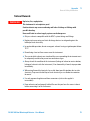
High Pressure Hazards
WA R N I N G
High velocity stream of volatile and/or toxic liquids.
If a line ruptures, a relief device opens, or a valve opens accidentally under pressure,
potentially hazardous high liquid pressures can be generated by the pump.
➔ Wear personal protective equipment when you inject samples or perform routine
maintenance.
➔ Never open a solvent line or valve under pressure. Stop the pump first and let the
pressure drop to zero.
➔ Always keep the doors and covers closed during operation.
➔ Read and adhere to all Notes, Cautions, and Warnings in the manual.
Ultraviolet Radiation
WA R N I N G
Irritation to the skin, eyes and upper respiratory system
➔ Ensure that protective lamp covers of variable and fixed wavelength detectors are in
place during operation.
➔ Do not look directly into detector fluid cells or at the UV light source. When
inspecting the light source or fluid cell, always use protective eye covering such as
borosilicate glass or polystyrene.
➔ Ventilate the area surrounding the detector such that the concentration of ozone
does not exceed the maximum permissible level. All venting must be to outside air,
never within the building.
Ozon generation
Ozone can be generated by radiation from the source lamps. The maximum
permissible exposure level is 0.1 ppm (0.2 mg/m³).
325 UV/VIS Dual Wavelength Detector - User Manual
77
9
Appendix
The Waste Electrical and Electronic Equipment Directive
The Waste Electrical and Electronic Equipment Directive
Abstract
The Waste Electrical and Electronic Equipment (WEEE) Directive
(2002/96/EC), adopted by EU Commission on 13 February 2003, is
introducing producer responsibility on all electric and electronic appliances
starting with 13 August 2005.
NOTE
This product complies with the WEEE Directive (2002/96/EC) marking requirements. The
affixed label indicates that you must not discard this electrical/electronic product in
domestic household waste.
Product Category:
With reference to the equipment types in the WEEE Directive Annex I, this product is
classed as a Monitoring and Control Instrumentation product.
NOTE
Do not dispose off in domestic household waste
To return unwanted products, contact your local Agilent office, or see www.agilent.com for
more information.
78
325 UV/VIS Dual Wavelength Detector - User Manual
Appendix
Batteries Information
9
Batteries Information
WA R N I N G
Lithium batteries may not be disposed-off into the domestic waste. Transportation of
discharged Lithium batteries through carriers regulated by IATA/ICAO, ADR, RID,
IMDG is not allowed.
Danger of explosion if battery is incorrectly replaced.
➔ Discharged Lithium batteries shall be disposed off locally according to national
waste disposal regulations for batteries.
➔ Replace only with the same or equivalent type recommended by the equipment
manufacturer.
WA R N I N G
Lithiumbatteri - Eksplosionsfare ved fejlagtig håndtering.
Udskiftning må kun ske med batteri af samme fabrikat og type.
➔ Lever det brugte batteri tilbage til leverandøren.
WA R N I N G
Lithiumbatteri - Eksplosionsfare.
Ved udskiftning benyttes kun batteri som anbefalt av apparatfabrikanten.
➔ Brukt batteri returneres appararleverandoren.
NOTE
Bij dit apparaat zijn batterijen geleverd. Wanneer deze leeg zijn, moet u ze niet weggooien
maar inleveren als KCA.
325 UV/VIS Dual Wavelength Detector - User Manual
79
9
Appendix
Radio Interference
Radio Interference
Cables supplied by Agilent Technologies are screened to provide optimized
protection against radio interference. All cables are in compliance with safety
or EMC regulations.
Test and Measurement
If test and measurement equipment is operated with unscreened cables, or
used for measurements on open set-ups, the user has to assure that under
operating conditions the radio interference limits are still met within the
premises.
80
325 UV/VIS Dual Wavelength Detector - User Manual
Appendix
CE Compliance
9
CE Compliance
Your Agilent 700 Series ICP-OES instrument has been designed to comply with
the requirements of the Electromagnetic Compatibility (EMC) Directive and
the Low Voltage (electrical safety) Directive (commonly referred to as the LVD)
of the European Union. Agilent has confirmed that each product complies
with the relevant Directives by testing a prototype against the prescribed EN
(European Norm) standards.
Proof that a product complies with these directives is indicated by:
• the CE Marking appearing on the rear of the product, and
• the documentation package that accompanies the product containing a
copy of the Declaration of Conformity. The Declaration of Conformity is the
legal declaration by Agilent that the product complies with the directives
listed above, and shows the EN standards to which the product was tested
to demonstrate compliance.
325 UV/VIS Dual Wavelength Detector - User Manual
81
9
Appendix
Electromagnetic Compatibility
Electromagnetic Compatibility
EN55011/CISPR11
Group 1 ISM equipment: group 1 contains all ISM equipment in which there is
intentionally generated and/or used conductively coupled radio- frequency
energy which is necessary for the internal functioning of the equipment itself.
Class A equipment is equipment suitable for use in all establishments other
than domestic and those directly connected to a low voltage power supply
network which supplies buildings used for domestic purposes.
This device complies with the requirements of CISPR11, Group 1, Class A as
radiation professional equipment. Therefore, there may be potential
difficulties in ensuring electromagnetic compatibility in other environments,
due to conducted as well as radiated disturbances.
Operation is subject to the following two conditions:
• This device may not cause harmful interference.
• This device must accept any interference received, including interference
that may cause undesired operation.
If this equipment does cause harmful interference to radio or television
reception, which can be determined by turning the equipment off and on, the
user is encouraged to try one or more of the following measures:
1 Relocate the radio or antenna.
2 Move the device away from the radio or television.
3 Plug the device into a different electrical outlet, so that the device and the
radio or television are on separate electrical circuits.
4 Make sure that all peripheral devices are also certified.
5 Make sure that appropriate cables are used to connect the device to
peripheral equipment.
6 Consult your equipment dealer, Agilent Technologies, or an experienced
technician for assistance.
7 Changes or modifications not expressly approved by Agilent Technologies
could void the user’s authority to operate the equipment.
ICES/NMB-001
This ISM device complies with Canadian ICES- 001. Cet appareil ISM est
conforme à la norme NMB-001 du Canada.
82
325 UV/VIS Dual Wavelength Detector - User Manual
Appendix
Agilent Technologies on Internet
9
Agilent Technologies on Internet
For the latest information on products and services visit our worldwide web
site on the Internet at:
http://www.agilent.com
Select Products/Chemical Analysis
It will provide also the latest firmware of the modules for download.
325 UV/VIS Dual Wavelength Detector - User Manual
83
Index
Index
A
Agilent
on internet 83
ambient laboratory temperature 26
ambient non-operating temperature 26
ambient operating temperature 26
analog output 62
B
battery
safety information
beam splitter 13
P
controls 9
lights 9
photodiode detectors 16
power consumption 26
power cords 24
F
features 8
flowcell types 20
flowcell 14
install 43
R
radio interference 80
relay output 63
removing
door 40
front panel 39
H
79
C
calibrating lamps 53
cleaning
exterior of the flowcell 48
flowcell 46
instrument 55
compliance
CE 81
condensation 25
connections
workstation control 61
D
detector outlet back pressure
restrictor 21
deuterium (UV) lamp 12
high pressure
hazard 77
humidity 26
S
safety information
lithium batteries 79
safety
general information 72
standards 26
site requirements
power cords 24
size 26
packed 26
specifications
performance 27
physical 26
symbols 73
synchronization signals 67
I
installing
door 41
internet 83
introduction 8
L
lithium batteries
79
M
masks
entrance 13
exit 13
monochromator 15
U
O
E
electronic waste
exterior
84
78
operating altitude
optical path 11
26
UV lamp
installing 50
removing 49
325 UV/VIS Dual Wavelength Detector - User Manual
Index
V
visible lamp 13
installing 52
removing 51
voltage 26
W
waste
electrical and electronic
equipment 78
WEEE directive 78
weight 26
packed 26
325 UV/VIS Dual Wavelength Detector - User Manual
85
www.agilent.com
In This Book
The manual describes the following:
• Introduction
• Site requirements
• Installation
• Usage
• Troubleshooting and diagnostics
• Error information
• Maintenance and repair
• Parts
• Safety
Agilent Technologies 2012
Printed in Germany
02/12
*G9309-90000*
*G9309-90000*
G9309-90000
Agilent Technologies