1
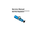
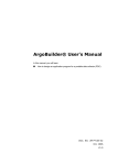
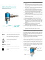
2. Warnings and Cautions
Micro Dial-Flowmeter
Instructions for Use
2.1
Warnings!
2.1.1
Read through this entire instruction manual before using or showing others
how to use a Micro Dial-Flowmeter. As with all medical equipment, attempting
to use this device without a thorough understanding of its operation may result
in patient or user injury.
2.1.2
Medical oxygen is or should be considered a drug and should only be used for
medical purposes as prescribed by a physician or authorised clinician and in
accordance with the medicinal product labelling.
2.1.3
If using a cylinder and regulator, ensure that the device is connected to the
regulator and the cylinder valve is properly opened before beginning therapy.
2.1.4
Ensure that the medical oxygen supply is sufficient for the proposed therapy
and is supplied within the pressure range given in the Device Specification. If
the supply is a gas cylinder, check the cylinder contents gauge regularly.
2.1.5
The Micro Dial-Flowmeter will deliver zero flow between flow settings. When
selecting a new flow setting, ensure that the flow selection dial clicks into place
and that a flow is correctly selected.
2.1.6
Do not cover the vent hole in the pre-regulator as this will change the device
calibration.
2.1.7
Do not submerge a Micro Dial-Flowmeter in any fluid. Ensure that no water is
allowed to enter ports or vent holes.
2.1.8
The accuracy of the flowmeter will be affected if the input pressure is other
than stated in the specifications.
2.1.9
Always disconnect the flowmeter from the gas supply when it is not in use.
2.1.10 Oxygen is not flammable, however an oxygen enriched atmosphere will
drastically increase the rate and severity of combustion. Oil and/or grease in
the presence of an oxygen enriched atmosphere will become highly
combustible. Oxygen must never be allowed to contact oil, grease or other
hydrocarbon based substances. Do not use oil or grease on this Micro DialFlowmeter.
2.1.11 Never administer oxygen while smoking or when near an open flame.
2.1.12 A gas specific connector is fitted to the Micro Dial-Flowmeter. Do not attempt
to modify the fittings to suit other gases or fitting systems.
2.1.13 Only appropriately trained personnel working in controlled conditions may
disassemble or assemble this Micro Dial-Flowmeter.
702-0072.01 – September 2009 – English
2.2
Cautions!
2.2.1
The performance of the flowmeter may be affected if it is stored or transported
in temperature outside of the range -20°C to +60°C (-4°F to +140°F).
3. Functional Description
3.1 Intended Use
1. Symbols
Warning!
Indicates a potentially hazardous situation which, if not
avoided, could result in personal injury to the user or others.
Caution!
Indicates a potentially hazardous situation which, if not
avoided, could result in damage to the equipment or property.
The Carnét Micro Dial-Flowmeter is intended to control the flow of medical oxygen
during oxygen therapy in both homecare and clinical environments. The flow selection
dial has 12 positions, including 11 discrete flow rates and an off position. Flow is
indicated in litres per minute (l/min) and is visible through a window adjacent to the
flow selection dial.
Medical oxygen is or should be considered a drug and should only be used for medical
purposes on the authority of a physician and then strictly in accordance with their
instructions. Always refer to the medical oxygen product labelling.
3.2 Technical Description
Attention, consult accompanying documents.
Use No Oil.
SERVICE DUE
Service due date.
RANGE
The range of flow rates. See Device Specification for details.
The Micro Dial-Flowmeter has a flow selection dial that is rotated to select the desired
oxygen flow. Rotating the dial changes the size of the orifice through which the gas
passes and consequently adjusts the gas flow rate.
The Micro Dial-Flowmeter includes a pre-regulator (pressure regulator) upstream of
the metering orifice plate. The pre-regulator provides a consistent pressure upstream
of the metering orifice plate over a wide range of inlet pressures.
The Micro Dial-Flowmeter has inlet and outlet connectors. The inlet connector is the
larger of the two and is a gas specific oxygen probe for connection to the oxygen
supply. The smaller outlet connector may be either a barbed outlet for direct
connection to oxygen delivery tubing or a threaded DISS (9/16” UNF) connector for
connection to a bubble humidifier.
Flow Selection
Dial
Medical Device: CE Marked to the Medical Device Directive
93/42/EEC.
Flow Indication
Window
Outlet
Connector
Gas Specific
Probe
Pre-Regulator
4. Operating Instructions
6. Troubleshooting
4.1 Preparation and Connection
Turn the flow selection dial fully clockwise and check that the indication in the
flowmeter window is zero.
Fault
Possible Cause
Connect the medical oxygen probe securely to the oxygen wall outlet or the equivalent
outlet of a pressure regulator connected to an oxygen cylinder.
Warning! Where the gas specific connector is dependent on a threaded fastener (e.g.
DISS CGA – V5 and AS 2896), make sure that the connection is properly tightened.
No gas flow
The medical gas terminal unit on
a pipeline system is isolated
For quick connector probes (e.g. BS5682, DIN, AFNOR), ensure that the connection is
correctly made by gently pulling the flowmeter before turning on the supply pressure.
If the medical oxygen supply is provided from a gas cylinder, turn on the oxygen supply
at the cylinder.
Internal/external leak
Connect a sufficient length of oxygen tubing (not supplied) to the outlet barb.
4.2 Testing Prior to Use
Insufficient gas flow
Turn the flow seclection dial to its highest setting and check that gas flow can be felt at
the patient end of the supply tubing. If no medical oxygen flow is sensed refer to the
troubleshooting guide in section 6 of this manual.
Turn off the oxygen flow by turning the flow selection dial fully clockwise.
4.3 Operation
Connect the free end of the oxygen tubing to the patient or patient enclosure using the
appropriate connector (not supplied).
Determine the approximate oxygen flow rate in l/min required for the patient. Turn
the flow selection dial until the closest rate to this is clearly visible in the flowmeter
window. Ensure the flow selection dial is in the latched position and the flow rate is
visible in the window. It will be obvious to the touch when the selection dial clicks into
place.
Warning! The Micro Dial-Flowmeter will deliver zero flow between flow settings.
Solution
The gas cylinder is turned off
The flowmeter is not connected
properly
The gas cylinder is empty
A filter is blocked
Selection dial set to ‘0’
Seal failure
A filter is partially occluded
The supply pressure is too low
and/or gas cylinder is nearly
empty
Check the gas supply
Check that the gas specific probe
is correctly connected
Replace the gas cylinder
Seek advice from someone
authorised to operate the
medical gas pipeline system
isolation valves
A service or repair is required
Select a positive flow rate
A service or repair is required
A service is required
Check the gas supply and/or
replace the gas cylinder
7. Parts and Spares List
Inlet Connector/Part Number
DISS
AS 2896
(CGA V-5)
Description
BS 5682
Micro Dial-Flowmeter - Range A - Hose Barb Outlet
816-0001
816-0026
816-0032
Micro Dial-Flowmeter - Range A - DISS Outlet
816-0006
-
816-0033
Micro Dial-Flowmeter - Range E - Hose Barb Outlet
816-0003
816-0027
816-0034
Micro Dial-Flowmeter - Range E - DISS Outlet
816-0011
-
816-0035
If the patient requires more or less oxygen flow, this is simply achieved in distinct
stages by rotating the flow selection dial.
Check the gas cylinder contents regularly (if applicable) during use of the Micro DialFlowmeter and be aware that the supply tubing may be a trip hazard.
4.4 After Use
When therapy is complete, disconnect the Micro Dial-Flowmeter from the gas supply.
Where the medical oxygen is being supplied from a cylinder, turn the cylinder off.
Spare Parts and Servicing
604-0035
Micro Dial-Flowmeter DISS Assembly
610-0040
Micro Dial-Flowmeter Service Kit (5 pack)
999-0003
Dial-Flowmeter Service
604-0034
Micro Dial-Flowmeter Output Barb Assembly
Store the Micro Dial-Flowmeter in a clean and dry environment between uses.
5. Maintenance
5.1 Interim Inspection
Micro Dial-Flowmeters should be cleaned, inspected for damage and performance
checked regularly. The frequency of such checks depends on usage, but as a guideline
if the flowmeter is used daily this should be preformed every six months, if used
infrequently then an annual check will suffice.
5.1.1
5.1.2
5.1.3
5.1.4
Cleaning
Wipe over the external surfaces of the Micro Dial-Flowmeter with an alcohol or
disinfecting wipe.
Internal Leak Test
Attach the flowmeter to the medical oxygen supply and turn the flow selection
dial to ‘0’. Connect a length of tubing to the outlet barb and immerse the other
end of the tube in water. Any gas bubbling through indicates an internal leak. If
any leakage is found the flowmeter should be removed from use and serviced
as described in section 5.2.
External Leak Test
Attach the flowmeter to the medical oxygen supply and turn the flow selection
dial to its highest flow rate (1 or 3 l/min depending on model). Apply an oxygen
compatible leak test solution to all joints and check for signs of leakage. If any
leakage is found the flowmeter should be removed from use and serviced as
described in section 5.2.
Flow Test
Verify flow rates at all flow settings against specification i.e. within ±10% at 1
l/min and above or ± 20% below 1 l/min.
8. Device Specification
Specification
Value
Nominal Inlet Pressure 345 kPa to 500 kPa (50 psi to 73 psi)
Supply Pressure
Maximum 1000 kPa (145 psi)
Minimum 280 kPa (40 psi)
Flow Settings
(l/min)
Range A: 0, 0.02, 0.03, 0.05, 0.08, 0.12, 0.2, 0.3, 0.5, 0.75, 1, 3
Range E: 0, 0.01, 0.02, 0.03, 0.04, 0.05, 0.06, 0.07, 0.08, 0.09, 0.1, 1
Filtration
Sintered bronze: 40 µm nominal first stage, 5 µm nominal second stage
Accuracy
±10% of reading at 1 l/min and above, ±20% of reading below 1 l/min
Varying Inlet
Pressure:
Effects on
Accuracy
Less than 3% of reading for ± 100 kPa change in
nominal input pressure. Less than 12% change in
reading in the range (280 kPa to 1000 kPa).
Varying Temperature: ±7% in the range 20°C ±20°C
Varying Outlet
Resistance:
Less than 1% of reading up to 5 kPa resistance
Environmental
Transport/Storage/Operation: -20°C to +60°C (-4°F to +140°F)
Humidity: 0-100% RH non-condensing
Regulatory
CE: Medical Device Directive 93/42/EEC – Class lla
FDA: Class 1
5.2 Service
The Micro Dial-Flowmeter must be serviced every 2 years to ensure that it continues to
perform in accordance with its specification. Micro Dial-Flowmeters have a Service Due
date on their labelling, which indicates when the next service is due.
Warning! Servicing must be carried out by a suitably qualified person working in a
controlled environment.
Full details of the recommended servicing requirements can be found in the Service
Manual. The Service Manual can be obtained from your local Carnét distributor, details
of which can be found at www.carnetmedical.com. Complete the service in
accordance with the instructions given in the Service Manual or return the device to a
recognised Carnét Service Centre on or before the date shown.
EN ISO 15002 – Flow-metering devices for connection to terminal units of
medical gas pipeline systems
Applied
Standards
EN 738-1 – Pressure regulators for use with medical gases - Part 1:
Pressure regulators and pressure regulators with metering devices.
EN ISO 15001 - Anaesthetic and respiratory equipment - Compatibility
with Oxygen